EP4512350A2 - Niedrigprofilelektroden für einen stosswellenkatheter - Google Patents
Niedrigprofilelektroden für einen stosswellenkatheter Download PDFInfo
- Publication number
- EP4512350A2 EP4512350A2 EP25150787.7A EP25150787A EP4512350A2 EP 4512350 A2 EP4512350 A2 EP 4512350A2 EP 25150787 A EP25150787 A EP 25150787A EP 4512350 A2 EP4512350 A2 EP 4512350A2
- Authority
- EP
- European Patent Office
- Prior art keywords
- balloon
- segment
- insulated wire
- distal
- emitter
- Prior art date
- Legal status (The legal status is an assumption and is not a legal conclusion. Google has not performed a legal analysis and makes no representation as to the accuracy of the status listed.)
- Pending
Links
Images






Classifications
-
- A—HUMAN NECESSITIES
- A61—MEDICAL OR VETERINARY SCIENCE; HYGIENE
- A61B—DIAGNOSIS; SURGERY; IDENTIFICATION
- A61B17/00—Surgical instruments, devices or methods
- A61B17/22—Implements for squeezing-off ulcers or the like on inner organs of the body; Implements for scraping-out cavities of body organs, e.g. bones; for invasive removal or destruction of calculus using mechanical vibrations; for removing obstructions in blood vessels, not otherwise provided for
- A61B17/22004—Implements for squeezing-off ulcers or the like on inner organs of the body; Implements for scraping-out cavities of body organs, e.g. bones; for invasive removal or destruction of calculus using mechanical vibrations; for removing obstructions in blood vessels, not otherwise provided for using mechanical vibrations, e.g. ultrasonic shock waves
- A61B17/22012—Implements for squeezing-off ulcers or the like on inner organs of the body; Implements for scraping-out cavities of body organs, e.g. bones; for invasive removal or destruction of calculus using mechanical vibrations; for removing obstructions in blood vessels, not otherwise provided for using mechanical vibrations, e.g. ultrasonic shock waves in direct contact with, or very close to, the obstruction or concrement
- A61B17/2202—Implements for squeezing-off ulcers or the like on inner organs of the body; Implements for scraping-out cavities of body organs, e.g. bones; for invasive removal or destruction of calculus using mechanical vibrations; for removing obstructions in blood vessels, not otherwise provided for using mechanical vibrations, e.g. ultrasonic shock waves in direct contact with, or very close to, the obstruction or concrement the ultrasound transducer being inside patient's body at the distal end of the catheter
-
- A—HUMAN NECESSITIES
- A61—MEDICAL OR VETERINARY SCIENCE; HYGIENE
- A61B—DIAGNOSIS; SURGERY; IDENTIFICATION
- A61B18/00—Surgical instruments, devices or methods for transferring non-mechanical forms of energy to or from the body
- A61B18/04—Surgical instruments, devices or methods for transferring non-mechanical forms of energy to or from the body by heating
- A61B18/12—Surgical instruments, devices or methods for transferring non-mechanical forms of energy to or from the body by heating by passing a current through the tissue to be heated, e.g. high-frequency current
- A61B18/14—Probes or electrodes therefor
-
- A—HUMAN NECESSITIES
- A61—MEDICAL OR VETERINARY SCIENCE; HYGIENE
- A61B—DIAGNOSIS; SURGERY; IDENTIFICATION
- A61B17/00—Surgical instruments, devices or methods
- A61B17/22—Implements for squeezing-off ulcers or the like on inner organs of the body; Implements for scraping-out cavities of body organs, e.g. bones; for invasive removal or destruction of calculus using mechanical vibrations; for removing obstructions in blood vessels, not otherwise provided for
- A61B17/22004—Implements for squeezing-off ulcers or the like on inner organs of the body; Implements for scraping-out cavities of body organs, e.g. bones; for invasive removal or destruction of calculus using mechanical vibrations; for removing obstructions in blood vessels, not otherwise provided for using mechanical vibrations, e.g. ultrasonic shock waves
- A61B17/22012—Implements for squeezing-off ulcers or the like on inner organs of the body; Implements for scraping-out cavities of body organs, e.g. bones; for invasive removal or destruction of calculus using mechanical vibrations; for removing obstructions in blood vessels, not otherwise provided for using mechanical vibrations, e.g. ultrasonic shock waves in direct contact with, or very close to, the obstruction or concrement
- A61B17/22022—Implements for squeezing-off ulcers or the like on inner organs of the body; Implements for scraping-out cavities of body organs, e.g. bones; for invasive removal or destruction of calculus using mechanical vibrations; for removing obstructions in blood vessels, not otherwise provided for using mechanical vibrations, e.g. ultrasonic shock waves in direct contact with, or very close to, the obstruction or concrement using electric discharge
-
- A—HUMAN NECESSITIES
- A61—MEDICAL OR VETERINARY SCIENCE; HYGIENE
- A61B—DIAGNOSIS; SURGERY; IDENTIFICATION
- A61B18/00—Surgical instruments, devices or methods for transferring non-mechanical forms of energy to or from the body
- A61B18/04—Surgical instruments, devices or methods for transferring non-mechanical forms of energy to or from the body by heating
- A61B18/12—Surgical instruments, devices or methods for transferring non-mechanical forms of energy to or from the body by heating by passing a current through the tissue to be heated, e.g. high-frequency current
- A61B18/1206—Generators therefor
-
- A—HUMAN NECESSITIES
- A61—MEDICAL OR VETERINARY SCIENCE; HYGIENE
- A61B—DIAGNOSIS; SURGERY; IDENTIFICATION
- A61B17/00—Surgical instruments, devices or methods
- A61B17/22—Implements for squeezing-off ulcers or the like on inner organs of the body; Implements for scraping-out cavities of body organs, e.g. bones; for invasive removal or destruction of calculus using mechanical vibrations; for removing obstructions in blood vessels, not otherwise provided for
- A61B17/22004—Implements for squeezing-off ulcers or the like on inner organs of the body; Implements for scraping-out cavities of body organs, e.g. bones; for invasive removal or destruction of calculus using mechanical vibrations; for removing obstructions in blood vessels, not otherwise provided for using mechanical vibrations, e.g. ultrasonic shock waves
- A61B17/22012—Implements for squeezing-off ulcers or the like on inner organs of the body; Implements for scraping-out cavities of body organs, e.g. bones; for invasive removal or destruction of calculus using mechanical vibrations; for removing obstructions in blood vessels, not otherwise provided for using mechanical vibrations, e.g. ultrasonic shock waves in direct contact with, or very close to, the obstruction or concrement
- A61B2017/22025—Implements for squeezing-off ulcers or the like on inner organs of the body; Implements for scraping-out cavities of body organs, e.g. bones; for invasive removal or destruction of calculus using mechanical vibrations; for removing obstructions in blood vessels, not otherwise provided for using mechanical vibrations, e.g. ultrasonic shock waves in direct contact with, or very close to, the obstruction or concrement applying a shock wave
-
- A—HUMAN NECESSITIES
- A61—MEDICAL OR VETERINARY SCIENCE; HYGIENE
- A61B—DIAGNOSIS; SURGERY; IDENTIFICATION
- A61B17/00—Surgical instruments, devices or methods
- A61B17/22—Implements for squeezing-off ulcers or the like on inner organs of the body; Implements for scraping-out cavities of body organs, e.g. bones; for invasive removal or destruction of calculus using mechanical vibrations; for removing obstructions in blood vessels, not otherwise provided for
- A61B2017/22051—Implements for squeezing-off ulcers or the like on inner organs of the body; Implements for scraping-out cavities of body organs, e.g. bones; for invasive removal or destruction of calculus using mechanical vibrations; for removing obstructions in blood vessels, not otherwise provided for with an inflatable part, e.g. balloon, for positioning, blocking, or immobilisation
- A61B2017/22062—Implements for squeezing-off ulcers or the like on inner organs of the body; Implements for scraping-out cavities of body organs, e.g. bones; for invasive removal or destruction of calculus using mechanical vibrations; for removing obstructions in blood vessels, not otherwise provided for with an inflatable part, e.g. balloon, for positioning, blocking, or immobilisation to be filled with liquid
-
- A—HUMAN NECESSITIES
- A61—MEDICAL OR VETERINARY SCIENCE; HYGIENE
- A61B—DIAGNOSIS; SURGERY; IDENTIFICATION
- A61B18/00—Surgical instruments, devices or methods for transferring non-mechanical forms of energy to or from the body
- A61B2018/00053—Mechanical features of the instrument of device
- A61B2018/00059—Material properties
- A61B2018/00071—Electrical conductivity
- A61B2018/00077—Electrical conductivity high, i.e. electrically conducting
-
- A—HUMAN NECESSITIES
- A61—MEDICAL OR VETERINARY SCIENCE; HYGIENE
- A61B—DIAGNOSIS; SURGERY; IDENTIFICATION
- A61B18/00—Surgical instruments, devices or methods for transferring non-mechanical forms of energy to or from the body
- A61B2018/00053—Mechanical features of the instrument of device
- A61B2018/00059—Material properties
- A61B2018/00071—Electrical conductivity
- A61B2018/00083—Electrical conductivity low, i.e. electrically insulating
-
- A—HUMAN NECESSITIES
- A61—MEDICAL OR VETERINARY SCIENCE; HYGIENE
- A61B—DIAGNOSIS; SURGERY; IDENTIFICATION
- A61B18/00—Surgical instruments, devices or methods for transferring non-mechanical forms of energy to or from the body
- A61B2018/00053—Mechanical features of the instrument of device
- A61B2018/00214—Expandable means emitting energy, e.g. by elements carried thereon
- A61B2018/0022—Balloons
-
- A—HUMAN NECESSITIES
- A61—MEDICAL OR VETERINARY SCIENCE; HYGIENE
- A61B—DIAGNOSIS; SURGERY; IDENTIFICATION
- A61B18/00—Surgical instruments, devices or methods for transferring non-mechanical forms of energy to or from the body
- A61B2018/00315—Surgical instruments, devices or methods for transferring non-mechanical forms of energy to or from the body for treatment of particular body parts
- A61B2018/00345—Vascular system
- A61B2018/00404—Blood vessels other than those in or around the heart
- A61B2018/00422—Angioplasty
-
- A—HUMAN NECESSITIES
- A61—MEDICAL OR VETERINARY SCIENCE; HYGIENE
- A61B—DIAGNOSIS; SURGERY; IDENTIFICATION
- A61B18/00—Surgical instruments, devices or methods for transferring non-mechanical forms of energy to or from the body
- A61B18/04—Surgical instruments, devices or methods for transferring non-mechanical forms of energy to or from the body by heating
- A61B18/12—Surgical instruments, devices or methods for transferring non-mechanical forms of energy to or from the body by heating by passing a current through the tissue to be heated, e.g. high-frequency current
- A61B18/14—Probes or electrodes therefor
- A61B2018/1467—Probes or electrodes therefor using more than two electrodes on a single probe
Definitions
- the present disclosure relates generally to shock wave electrodes, and more specifically, to electrodes for the generation of shock waves within vascular structures.
- the present invention relates to a treatment system for percutaneous coronary angioplasty or peripheral angioplasty in which an angioplasty balloon is used to dilate a lesion (e.g., calcified lesion) and restore normal blood flow in the artery.
- a catheter carrying a balloon is advanced into the vasculature along a guide wire until the balloon is aligned with calcified plaques.
- the balloon is then pressurized to reduce or break the calcified plaques and push them back into the vessel wall.
- a treatment system that includes electrodes within an angioplasty type balloon.
- the balloon is advanced to the region of an occlusion.
- the balloon is then initially pressurized with a conductive fluid.
- a series of high voltage pulses are applied to the electrodes within the balloon, with each pulse generating a shock wave in the conductive fluid.
- the shock waves pass through the balloon wall and into the occlusion, cracking the calcified plaques. Once the calcified plaques are cracked, the balloon can be further expanded to open the vessel.
- Such system is disclosed in U.S. Pat. Nos. 8,956,371 , 8,888,788 , and U.S. Pub. No.
- the present invention relates techniques for treating tight, hard-to-cross calcific lesions by positioning low-profile shock wave electrodes at the distal portion of the balloon, including the distal leg segment and/or the distal cone segment of the angioplasty balloon.
- An exemplary device for generating shock waves comprises an elongated tube; a balloon wrapped circumferentially around a portion of the elongated tube, the balloon comprising: a distal end sealed to the elongated tube, a leg segment proximal to the distal end of the balloon, a cone segment proximal to the leg segment of the balloon, and a straight segment proximal to the cone segment of the balloon, wherein, when the balloon is inflated: the leg segment is substantially cylindrical or is of a tapered shape with an average diameter, the cone segment is of a tapered shape with an average diameter greater than the average diameter of the leg segment, and the straight segment is of a substantially cylindrical shape with a diameter greater than the average diameter of the cone segment; and at least one distal emitter configured to generate shock waves, wherein the at least one distal emitter is positioned in the leg segment or the cone segment of the balloon.
- a second vertex angle between the cone segment of the balloon and the elongated tube is larger than the first vertex angle
- the at least one distal emitter comprises a first electrode pair, the first electrode pair comprising: a conductive portion of a first insulated wire and a conductive portion of a second insulated wire.
- the first insulated wire comprises a flattened distal segment, and the first portion of insulation is removed from the flattened distal segment of the first insulated wire
- the second insulated wire comprises a flattened distal segment, and the second portion of insulation is removed from the flattened distal segment of the second insulated wire.
- a diameter of the flattened distal segment of the first insulated wire is approximately 47% to 75% of a diameter of a proximal segment of the first insulated wire
- a diameter of the flattened distal segment of the second insulated wire is approximately 47% to 75% of a diameter of a proximal segment of the second insulated wire.
- a layer of polymer covers at least a portion of the first insulated wire and the second insulated wire, such that the conductive portion of the first insulated wire is held a controlled distance apart from the conductive portion of the second insulated wire.
- the at least one distal emitter further comprises a second electrode pair, the second electrode pair comprising: a further conductive portion of the second insulated wire and a conductive portion of a third insulated wire.
- the at least one distal emitter further comprises a second electrode pair and a third electrode pair, wherein the second electrode pair comprises: a further conductive portion of the second insulated wire and a first side edge of a conductive sheath wrapped circumferentially around the elongated tube; and wherein the third electrode pair comprises: a second side edge of the conductive sheath and a conductive portion of a third insulated wire.
- the elongated tube is tapered toward the distal end.
- An exemplary method of generating shock waves comprises introducing a shock wave device into a patient's vasculature, the shock wave device comprising: a balloon comprising: a distal end, a leg segment proximal to the distal end of the balloon, a cone segment proximal to the leg segment of the balloon, and a straight segment proximal to the cone segment of the balloon; at least one distal emitter in the leg segment or the cone segment of the balloon; and at least one proximal emitter in the straight segment of the balloon.
- the method includes advancing the shock wave device in the patient's vasculature such that the distal leg segment of the balloon is advanced as far into the calcified lesion as possible; inflating the balloon with a conductive fluid such that the inflated balloon is gently fixed to walls of the vasculature in direct proximity with the calcified lesion, wherein, when the balloon is inflated, the leg segment is substantially cylindrical or is of a tapered shape with an average diameter, the cone segment is of a tapered shape with an average diameter greater than the average diameter of the leg segment, and the straight segment is of a substantially cylindrical shape with a diameter greater than the average diameter of the cone segment; activating a voltage source to generate shock waves at the at least one distal emitter; and after activating the voltage source, deflating the balloon.
- the method includes further advancing the shock wave device in the patient's vasculature such that the straight segment of the balloon is advanced as far into the calcified lesion as possible; inflating the balloon with the conductive fluid such that the inflated balloon is gently fixed to walls of the vasculature in direct proximity with the calcified lesion; and activating the voltage source to generate shock waves at the at least one proximal emitter.
- the first stage is repeated until the calcified lesion is modified such that the straight segment of the balloon is able to advance into the calcified lesion.
- activating the voltage source during the second stage generates shock waves at both the at least one proximal emitter and the at least one distal emitter.
- the at least one distal emitter is positioned in the leg segment of the balloon
- the at least one distal emitter is positioned in the cone segment of the balloon.
- the at least one distal emitter comprises a first distal emitter positioned in the leg segment of the balloon and a second distal emitter positioned in the cone segment of the balloon.
- An exemplary device for generating shock waves comprises a balloon comprising: a distal end, a leg segment proximal to the distal end of the balloon, a cone segment proximal to the leg segment of the balloon, wherein, when the balloon is inflated: the leg segment is cylindrical or is of a tapered shape with a first vertex angle, and the cone segment is of a tapered shape with a second vertex angle larger than the first vertex angle, an elongated tube extending through the balloon, wherein the balloon wraps around a longitudinal segment of the elongated tube, wherein the distal end of the balloon is sealed to the elongated tube; an electrode pair between the elongated tube and the leg segment of the balloon, comprising: a conductive portion of a first insulated wire extending over the elongated tube, a conductive portion of a second insulated wire extending over the elongated tube, wherein, when a voltage is applied across the first insulated wire
- the electrode pair is a first electrode pair
- the device comprises a second electrode pair within the cone segment of the balloon.
- the second electrode pair comprises: a conductive portion of the second insulated wire extending over the elongated tube; and a conductive portion of a third insulated wire extending over the elongated tube.
- the second electrode pair comprises: a conductive portion of the second insulated wire extending over the elongated tube; and a conductive sheath circumferentially mounted around the elongated tube.
- the vertex angle 200a is between 5-20° and the vertex angle 200b is between 0-5°.
- the leg segment is of a cylindrical shape (i.e., 200b is 0 degree).
- E1 distal emitter
- the gap is between around 0.001"-0.003".
- E1 can be located at ⁇ 0.5-1mm of the distal end of the gap.
- the leg segment is approximately 3.5-5.0mm long, and the cone segment is approximately 4.5-5.5mm long.
- the elongated tube 104 includes a number of longitudinal grooves or channels configured for retaining wires and/or inner electrodes.
- the elongated tube 104 also includes a lumen through which a guide wire 120 is inserted.
- insulated wires 130, 132, 134, 136, and 138 are placed along the elongated tube 104 (e.g., within the grooves of the elongated tube 104).
- a number of conductive sheaths 112, 114, and 116 are circumferentially mounted around the elongated tube 104.
- a variable high voltage pulse generator 150 can provide a first voltage channel between wire 130 and 134 and a second voltage channel between 130 and 132.
- the insulated wires and the sheaths form seven electrode pairs that can be activated to generate shock waves at 7 locations (e.g., along the length of the vessel) simultaneously or in multiple stages of the IVL treatment, as discussed in detail below.
- the balloon distal leg segment and cone segment are advanced as far as possible inside the tight lesion.
- a guide catheter is positioned such that its distal tip is proximal to sheath 116 to retain the deflated state of the straight portion of the balloon.
- the balloon is then inflated by a conductive fluid (e.g., saline and/or saline mixed with an image contrast agent) to IVL pressure, allowing conductive fluid to fill the leg segment and cone segment of the balloon.
- a voltage is applied between wires 130 and 134 to activate the three most distal emitters E1, E2, and E3 (e.g., for 1 cycle).
- embodiments of the present invention amount to a crossing and IVL combination catheter.
- Emitters in the distal balloon leg and cone segments are used to facilitate crossing of the balloon catheter in tight, hard-to-cross lesions.
- Emitters within the straight segment deliver IVL treatment and dilatation to calcified lesions.
- the angioplasty balloon is made of soft grade polymer extrusion (e.g., certain Pebax material) allowing the distal cone and leg segments to withstand higher heat and pressure from IVL treatment.
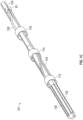
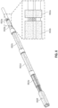
- FIG. 1C depicts exemplary shock wave electrode assemblies included in the exemplary shock wave angioplasty device 100 of FIG. 1B , according to some embodiments of the invention.
- the elongated tube 104 provides four longitudinal grooves, as indicated by the proximal end of the elongated tube.
- the elongated tube 104 is tapered toward its distal end.
- a number of insulated wires (e.g., lead or interstation wires) 130, 132, 134, and 136 are disposed on the outer surface of the elongated tube 104 such that they extend along the length of the elongated tube.
- the wires can be straight or twisted.
- wire 132 is disposed within one groove of the elongated tube 104, while wire 130 is twisted and different segments of the wire 130 are disposed along different grooves or outer surface of the elongated tube 104.
- the shock wave angioplasty device 100 further includes three conductive sheaths 112, 114, and 116 each circumferentially mounted around the elongated tube 104.
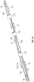
- FIG. 1D depicts the relative placement of the wires and the conductive sheaths, with the elongated tube removed.
- FIG. 1D further depicts two current flows 1a and 1b for generating seven sources of shock waves, as described with reference to FIGS. 1E and 1F .
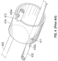
- the first inner electrode 430a is adjacent to, but not in contact with, a distal side edge 413 of the conductive sheath 412.
- the conductive sheath 412 functions as an outer electrode, and the inner electrode 430a is placed a controlled distance apart from the distal side edge 413 of the first conductive sheath to allow for a reproducible arc for a given voltage and current.
- the electrical arcs are then used to generate shock waves in the conductive fluid.
- a first shock wave is created across the inner electrode 430a and the distal side edge 413 of the conductive sheath 412.
- a portion of the insulated wire 432 is removed to form a second inner electrode 432a.
- the second inner electrode 432a is adjacent to, but not in contact with, a proximal side edge 411 of the conductive sheath 412.
- the first inner electrode 430a and the second inner electrode 432a are positioned circumferentially 180 degrees from each other.
- the conductive sheath 412 acts as an outer electrode and a second shock wave is created across the second inner electrode 432a and the proximal side edge 411 of the first conductive sheath 412.
- the diagonal placement of the inner electrodes allows the sonic output to be distributed more evenly longitudinally along the balloon while making the shock waves less annular.
- One of ordinary skill in the art should recognize that the location of a shock wave can be configured in a flexible manner by arranging the corresponding wire and the corresponding conductive sheath (and the location of the corresponding cut-out on the sheath, if available) accordingly.
- two emitters can be formed along the same side edge of the sheath; further, a shock wave can be generated between an inner electrode and a straight side edge of the conductive sheath that does not include any cut-outs.
- An emitter can also be formed by the distal portions of two wires, as depicted in FIG. 5 .
- a portion of the insulating layer of the wire 502 is removed near the distal end of the wire to expose an electrically conductive wire portion, forming an electrode 502a.
- a portion of the insulating layer of the wire 504 is removed near the distal end of the wire to expose an electrically conductive wire portion, forming an electrode 504a.
- the pair of electrodes are adjacent to, but not in contact with, each other. Specifically, the pair of electrodes are placed a controlled distance apart to allow for a reproducible arc for a given voltage and current. The electrical arcs are then used to generate shock waves in the conductive fluid.
- the wires 502 and 504 can be flattened to reduce the profile of the electrode pair. As shown in FIG. 5 , while the proximal end of the wire 504 retains its original shape (i.e., cylindrical), the distal segment of the wire 504 has been flattened to reduce its profile. In some embodiments, a wire of 0.0053"-0.0064" in diameter can be flattened to 0.0030"-0.0040" in diameter, resulting in the flattened distal segment of the wire having a diameter that is approximately 47% to 75% relative to the diameter of the unflattened proximal segment of the wire. Having wires in the distal leg may affect the dimension and flexibility of the device, thus deliverability.
- a layer of polyethylene terephthalate (“PET”) can cover the wires before and after the cutouts to hold down the wires.
- PET polyethylene terephthalate
- a plurality of PET bands 602a-f are used to secure the wires to the elongated tube.
- PET bands 602a and 602b covers the two wires forming the distal electrode pair before and after the cutouts. In some embodiments, these cutouts are recessed from the top surface by .00025" (thickness of the PET).
- FIGS. 1E and 1F schematically depict two electrical diagrams of the configuration of FIGS. 1B-D , in accordance with some embodiments.
- a first high voltage is applied (e.g., using the high voltage pulse generator 150 of FIG. 1B ) across the proximal end of the insulated wire 130 and the proximal end of the insulated wire 134, a current 1a may flow as indicated by the arrows, with the insulated wire 130 as the common ground wire (i.e., connecting to a ground or negative channel).
- the current flows from the proximal end of the insulated wire 134 toward to the distal end of the insulated wire 134 and, via the insulation removed spot that is electrically conductive (i.e., inner electrode 134a), to the proximal side edge of the conductive sheath 116 (i.e., outer electrode).
- the duration and the magnitude of the voltage pulse are set to be sufficient to generate a gas bubble at the surface of the inner electrode 134a a causing a plasma arc of electric current to traverse the bubble and create a rapidly expanding and collapsing bubble, which creates the mechanical shock wave in the balloon (“SW1").
- the inner electrode 134a and the inner electrode 138a a are located circumferentially opposite to each other (e.g., 180 degrees apart around the circumference of the elongated tube), and thus the first shock wave and the second shock wave may propagate in opposite directions, extending outward from the side of the elongated tube.
- the current 1a may further traverse to the distal end of the wire 138 and, via the insulation removed spot that is electrically conductive near the distal end of the wire 138 (i.e., the electrode 138b), to the insulation removed spot that is electrically conductive near the distal end of the wire 130 (i.e., the electrode 130a).
- the high voltage pulse generator may apply a voltage pulse such that the potential difference between the 138b and 130a is high enough to form a plasma arc between them, generating a bubble that gives rise to a third shock wave ("SW3"). Similar to the 1 st and 2 nd shockwaves, the shockwave propagates and extends outward from the 2 insulation removed spots 138b and 130a.
- a current 1b may flow as indicated by the arrows, with the insulated wire 130 as the common ground wire (i.e., connecting to a ground or negative channel).
- the current flows from the proximal end of the insulated wire 132 toward to the distal end of the insulated wire 132 and, via the insulation removed spot that is electrically conductive (i.e., inner electrode 132a), to the distal side edge of the conductive sheath 112 (i.e., outer electrode), generating shock waves ("SW4").
- the current 1b may further traverse from the proximal side edge of the conductive sheath 112 (i.e., outer electrode) to the insulated wire 136, via the insulation removed spot near the proximal end of the insulated wire 136 (i.e., inner electrode 136a), generating shock waves ("SW5").
- 132a and 136a are positioned circumferentially 180 degrees from each other on opposite edges of the conductive sheath 112.
- the current 1b may further traverse toward the distal end of the wire 136 and, via the insulation removed spot that is electrically conductive near the distal end of the wire 136 (i.e., the electrode 136b), to the proximal side edge of conductive sheath 114, generating shock waves ("SW6").
- the current 1b may further traverse from the distal side edge of the conductive sheath 114) to the insulated wire 130, via the insulation removed spot on the insulated wire 130 (i.e., inner electrode 130b), generating shock waves ("SW7").
- the current then returns to the voltage source generator via the insulated wire 130 to a voltage output port.
- 136b and 130b are positioned circumferentially 180 degrees from each other on opposite edges of conductive sheath 114.
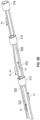
- an elongated tube 204 has a tapered distal portion. All wires are tacked down using adhesive. A layer of polymer, such as polyethylene terephthalate (“PET”), can cover the wires before and after the emitters / insulation removed spots to hold down the wires. A number of insulated wires (e.g., lead or interstation wires) 230, 234, 236, and 238 are disposed on the outer surface of the elongated tube 204 such that they extend along the length of the elongated tube. The wires can be straight or twisted. Further, two conductive sheaths 212 and 214 each circumferentially mounted around the elongated tube 204.
- PTT polyethylene terephthalate
- the current flows from the proximal end of the insulated wire 232 toward to the distal end of the insulated wire 232 and, via the insulation removed spot that is electrically conductive (i.e., inner electrode 232a), to the distal side edge of the conductive sheath 212 (i.e., outer electrode), generating shock waves ("SW3").
- the current 2b may further traverse from the proximal side edge of the conductive sheath 212 (i.e., outer electrode) to the insulated wire 236, via the insulation removed spot near the proximal end of the insulated wire 236 (i.e., inner electrode 236a), generating shock waves ("SW4").
- 232a and 236a are positioned circumferentially 180 degrees from each other on opposite edges of the conductive sheath 212.
- the current 2b may further traverse toward the distal end of the wire 236 and, via the insulation removed spot that is electrically conductive near the distal end of the wire 236 (i.e., the electrode 236b), to the proximal side edge of conductive sheath 214, generating shock waves ("SW5").
- the current 2b may further traverse from the distal side edge of the conductive sheath 214) to the insulated wire 230, via the insulation removed spot on the insulated wire 230 (i.e., inner electrode 230b), generating shock waves ("SW6").
- the current then returns to the voltage source generator via the insulated wire 230 to a voltage output port.
- 236b and 230b are positioned circumferentially 180 degrees from each other on opposite edges of conductive sheath 214.
- the current flows depicted in FIG. 2C and 2D can occur simultaneously (e.g., by applying two voltage channels simultaneously) or at different times depending on the stage of the treatment.
- only current 2a is activated during the first stage of the treatment, thus activating only SW1, and SW2. This is to break loose calcifications in a tight lesion that only the distal segments (e.g., distal cone and/or distal leg) of the balloon can cross or come close to.
- the balloon is deflated and advanced further into the lesion.
- the balloon is again inflated to IVL pressure.
- all of the emitters are activated simultaneously as shown in FIGS. 2C and 2D .
- Shock waves generated by the proximal emitters i.e., SW3, SW4, SW5, SW6
- the two distal emitters i.e., SW1, SW2
- SW3, SW4, SW5, and SW6 are activated in the 2 nd stage.
- FIGS. 3A-D depict another exemplary shock wave electrode assemblies 301 that can be included in the exemplary shock wave angioplasty device 100 of FIG. 1B , according to some embodiments of the invention.
- the embodiment 301 does not include any wire-to-wire electrode pairs. Rather, all emitters are formed by a side edge of a conductive sheath and a conductive portion of a wire. Further, the two most distal emitters (formed at the two side edges of the conductive sheath 316) are both disposed in the cone segment ("M") of a balloon.
- a number of insulated wires e.g., lead or interstation wires
- a number of insulated wires are disposed on the outer surface of the elongated tube 304 such that they extend along the length of the elongated tube.
- the wires can be straight or twisted.
- three conductive sheaths 312, 314, and 316 each circumferentially mounted around the elongated tube 304.
- FIG. 3B depicts the relative placement of the wires and the conductive sheaths, with the elongated tube removed.
- FIG. 3B further depicts two current flows 3a and 3b for generating six sources of shock waves, as described with reference to FIGS. 3C and 3D .
- FIGS. 3C and 3D schematically depict two electrical diagrams of the configuration of FIGS. 3A-B , in accordance with some embodiments.
- a first high voltage is applied (e.g., using the high voltage pulse generator 150 of FIG. 1B ) across the proximal end of the insulated wire 330 and the proximal end of the insulated wire 334, a current 3a may flow as indicated by the arrows, with the insulated wire 330 as the common ground wire (i.e., connecting to a ground or negative channel).
- the current flows from the proximal end of the insulated wire 334 toward to the distal end of the insulated wire 334 and, via the insulation removed spot that is electrically conductive on wire 334 (i.e., electrode 334a), to the proximal side edge of the conductive sheath 316, generating shock waves ("SW1").
- SW1 shock waves
- the current 3a may further traverse from the distal side edge of the conductive sheath 316 and, via the insulation removed spot near the distal end of the insulated wire 330 (i.e., electrode 330a), to the wire 330, generating shock waves ("SW2").
- the current 3a then returns to the voltage source generator via the insulated wire 330 to a voltage output port (not depicted), which may be a negative channel or a ground channel.
- a connector (not depicted) may be provided between the insulated wires 334 and 330 and the voltage pulse generator so that the wires may be easily connected to the output ports of the high voltage generator.
- a current 3b may flow as indicated by the arrows, with the insulated wire 330 as the common ground wire (i.e., connecting to a ground or negative channel).
- the current flows from the proximal end of the insulated wire 332 toward to the distal end of the insulated wire 332 and, via the insulation removed spot that is electrically conductive (i.e., inner electrode 332a), to the distal side edge of the conductive sheath 312 (i.e., outer electrode), generating shock waves ("SW3").
- the current 2b may further traverse from the proximal side edge of the conductive sheath 312 (i.e., outer electrode) to the insulated wire 336, via the insulation removed spot near the proximal end of the insulated wire 336 (i.e., inner electrode 336a), generating shock waves ("SW4").
- 332a and 336a are positioned circumferentially 180 degrees from each other on opposite edges of the conductive sheath 312.
- the current 3b may further traverse toward the distal end of the wire 336 and, via the insulation removed spot that is electrically conductive near the distal end of the wire 336 (i.e., the electrode 336b), to the proximal side edge of conductive sheath 314, generating shock waves ("SW5").
- the current 3b may further traverse from the distal side edge of the conductive sheath 314) to the insulated wire 330, via the insulation removed spot on the insulated wire 330 (i.e., inner electrode 330b), generating shock waves ("SW6").
- the current then returns to the voltage source generator via the insulated wire 330 to a voltage output port.
- 336b and 330b are positioned circumferentially 180 degrees from each other on opposite edges of conductive sheath 314.
- the current flows depicted in FIG. 3C and 3D can occur simultaneously (e.g., by applying two voltage channels simultaneously) or at different times depending on the stage of the treatment.
- only current 3a is activated during the first stage of the treatment, thus activating only SW1, and SW2. This is to break loose calcifications in a tight lesion that only the distal segments (e.g., distal cone and/or distal leg) of the balloon can cross or come close to.
- the balloon is deflated and advanced further into the lesion.
- the balloon is again inflated to IVL pressure.
- all of the emitters are activated simultaneously as shown in FIGS. 3C and 3D .
- Shock waves generated by the proximal emitters i.e., SW3, SW4, SW5, SW6 provide additional treatment to the calcific lesion, while shock waves generated by the three distal emitters (i.e., SW1, SW2) allows further advancement of the balloon.
Landscapes
- Health & Medical Sciences (AREA)
- Surgery (AREA)
- Engineering & Computer Science (AREA)
- Life Sciences & Earth Sciences (AREA)
- Veterinary Medicine (AREA)
- General Health & Medical Sciences (AREA)
- Nuclear Medicine, Radiotherapy & Molecular Imaging (AREA)
- Public Health (AREA)
- Biomedical Technology (AREA)
- Heart & Thoracic Surgery (AREA)
- Medical Informatics (AREA)
- Molecular Biology (AREA)
- Animal Behavior & Ethology (AREA)
- Otolaryngology (AREA)
- Plasma & Fusion (AREA)
- Physics & Mathematics (AREA)
- Mechanical Engineering (AREA)
- Orthopedic Medicine & Surgery (AREA)
- Vascular Medicine (AREA)
- Media Introduction/Drainage Providing Device (AREA)
- Surgical Instruments (AREA)
Applications Claiming Priority (4)
| Application Number | Priority Date | Filing Date | Title |
|---|---|---|---|
| US201962904839P | 2019-09-24 | 2019-09-24 | |
| EP20764208.3A EP4034004B1 (de) | 2019-09-24 | 2020-08-13 | Niedrigprofilelektroden für einen stosswellenkatheter |
| PCT/US2020/046134 WO2021061294A1 (en) | 2019-09-24 | 2020-08-13 | Low profile electrodes for a shock wave catheter |
| EP23208960.7A EP4295788B1 (de) | 2019-09-24 | 2020-08-13 | Niedrigprofilelektroden für einen stosswellenkatheter |
Related Parent Applications (3)
| Application Number | Title | Priority Date | Filing Date |
|---|---|---|---|
| EP23208960.7A Division EP4295788B1 (de) | 2019-09-24 | 2020-08-13 | Niedrigprofilelektroden für einen stosswellenkatheter |
| EP23208960.7A Division-Into EP4295788B1 (de) | 2019-09-24 | 2020-08-13 | Niedrigprofilelektroden für einen stosswellenkatheter |
| EP20764208.3A Division EP4034004B1 (de) | 2019-09-24 | 2020-08-13 | Niedrigprofilelektroden für einen stosswellenkatheter |
Publications (2)
| Publication Number | Publication Date |
|---|---|
| EP4512350A2 true EP4512350A2 (de) | 2025-02-26 |
| EP4512350A3 EP4512350A3 (de) | 2025-05-07 |
Family
ID=72266834
Family Applications (3)
| Application Number | Title | Priority Date | Filing Date |
|---|---|---|---|
| EP20764208.3A Active EP4034004B1 (de) | 2019-09-24 | 2020-08-13 | Niedrigprofilelektroden für einen stosswellenkatheter |
| EP25150787.7A Pending EP4512350A3 (de) | 2019-09-24 | 2020-08-13 | Niedrigprofilelektroden für einen stosswellenkatheter |
| EP23208960.7A Active EP4295788B1 (de) | 2019-09-24 | 2020-08-13 | Niedrigprofilelektroden für einen stosswellenkatheter |
Family Applications Before (1)
| Application Number | Title | Priority Date | Filing Date |
|---|---|---|---|
| EP20764208.3A Active EP4034004B1 (de) | 2019-09-24 | 2020-08-13 | Niedrigprofilelektroden für einen stosswellenkatheter |
Family Applications After (1)
| Application Number | Title | Priority Date | Filing Date |
|---|---|---|---|
| EP23208960.7A Active EP4295788B1 (de) | 2019-09-24 | 2020-08-13 | Niedrigprofilelektroden für einen stosswellenkatheter |
Country Status (7)
| Country | Link |
|---|---|
| US (2) | US12426938B2 (de) |
| EP (3) | EP4034004B1 (de) |
| JP (2) | JP7573603B2 (de) |
| CN (1) | CN114746032A (de) |
| AU (1) | AU2020354885B2 (de) |
| ES (2) | ES3018918T3 (de) |
| WO (1) | WO2021061294A1 (de) |
Families Citing this family (70)
| Publication number | Priority date | Publication date | Assignee | Title |
|---|---|---|---|---|
| US9642673B2 (en) | 2012-06-27 | 2017-05-09 | Shockwave Medical, Inc. | Shock wave balloon catheter with multiple shock wave sources |
| US8888788B2 (en) | 2012-08-06 | 2014-11-18 | Shockwave Medical, Inc. | Low profile electrodes for an angioplasty shock wave catheter |
| EP2882357A1 (de) | 2012-08-08 | 2015-06-17 | Shockwave Medical, Inc. | Schockwellen-valvuloplastie mit mehreren ballons |
| US9333000B2 (en) | 2012-09-13 | 2016-05-10 | Shockwave Medical, Inc. | Shockwave catheter system with energy control |
| US9522012B2 (en) | 2012-09-13 | 2016-12-20 | Shockwave Medical, Inc. | Shockwave catheter system with energy control |
| WO2017087195A1 (en) | 2015-11-18 | 2017-05-26 | Shockwave Medical, Inc. | Shock wave electrodes |
| US10226265B2 (en) | 2016-04-25 | 2019-03-12 | Shockwave Medical, Inc. | Shock wave device with polarity switching |
| EP3777723B1 (de) | 2016-10-06 | 2024-01-17 | Shockwave Medical, Inc. | Aortensegelreparatur mithilfe von stosswellenapplikatoren |
| US10966737B2 (en) | 2017-06-19 | 2021-04-06 | Shockwave Medical, Inc. | Device and method for generating forward directed shock waves |
| US10709462B2 (en) | 2017-11-17 | 2020-07-14 | Shockwave Medical, Inc. | Low profile electrodes for a shock wave catheter |
| US11819229B2 (en) | 2019-06-19 | 2023-11-21 | Boston Scientific Scimed, Inc. | Balloon surface photoacoustic pressure wave generation to disrupt vascular lesions |
| US11717139B2 (en) | 2019-06-19 | 2023-08-08 | Bolt Medical, Inc. | Plasma creation via nonaqueous optical breakdown of laser pulse energy for breakup of vascular calcium |
| US12402946B2 (en) | 2019-06-19 | 2025-09-02 | Boston Scientific Scimed, Inc. | Breakdown of laser pulse energy for breakup of vascular calcium |
| US11660427B2 (en) | 2019-06-24 | 2023-05-30 | Boston Scientific Scimed, Inc. | Superheating system for inertial impulse generation to disrupt vascular lesions |
| US20200406010A1 (en) | 2019-06-26 | 2020-12-31 | Boston Scientific Scimed, Inc. | Side light direction plasma system to disrupt vascular lesions |
| EP4034005B1 (de) | 2019-09-24 | 2024-12-18 | Shockwave Medical, Inc. | Läsionskreuzender stosswellenkatheter |
| JP7515576B2 (ja) | 2019-09-24 | 2024-07-12 | ショックウェーブ メディカル, インコーポレイテッド | 身体管腔内の血栓を治療するためのシステム |
| US11583339B2 (en) | 2019-10-31 | 2023-02-21 | Bolt Medical, Inc. | Asymmetrical balloon for intravascular lithotripsy device and method |
| US12102384B2 (en) | 2019-11-13 | 2024-10-01 | Bolt Medical, Inc. | Dynamic intravascular lithotripsy device with movable energy guide |
| US12274497B2 (en) | 2019-12-18 | 2025-04-15 | Bolt Medical, Inc. | Multiplexer for laser-driven intravascular lithotripsy device |
| US12446961B2 (en) | 2020-02-10 | 2025-10-21 | Bolt Medical, Inc. | System and method for pressure monitoring within a catheter system |
| US11672599B2 (en) | 2020-03-09 | 2023-06-13 | Bolt Medical, Inc. | Acoustic performance monitoring system and method within intravascular lithotripsy device |
| US12611253B2 (en) | 2020-03-18 | 2026-04-28 | Boston Scientific Scimed, Inc. | Optical analyzer assembly and method for intravascular lithotripsy device |
| US11707323B2 (en) | 2020-04-03 | 2023-07-25 | Bolt Medical, Inc. | Electrical analyzer assembly for intravascular lithotripsy device |
| US20210353359A1 (en) | 2020-05-12 | 2021-11-18 | Bolt Medical, Inc. | Active alignment system and method for optimizing optical coupling of multiplexer for laser-driven intravascular lithotripsy device |
| US12295654B2 (en) | 2020-06-03 | 2025-05-13 | Boston Scientific Scimed, Inc. | System and method for maintaining balloon integrity within intravascular lithotripsy device with plasma generator |
| US12207870B2 (en) | 2020-06-15 | 2025-01-28 | Boston Scientific Scimed, Inc. | Spectroscopic tissue identification for balloon intravascular lithotripsy guidance |
| US11992232B2 (en) | 2020-10-27 | 2024-05-28 | Shockwave Medical, Inc. | System for treating thrombus in body lumens |
| US12232755B2 (en) | 2020-12-11 | 2025-02-25 | Shockwave Medical, Inc. | Lesion crossing shock wave catheter |
| US12016610B2 (en) | 2020-12-11 | 2024-06-25 | Bolt Medical, Inc. | Catheter system for valvuloplasty procedure |
| WO2022154954A1 (en) | 2021-01-12 | 2022-07-21 | Bolt Medical, Inc. | Balloon assembly for valvuloplasty catheter system |
| US11672585B2 (en) | 2021-01-12 | 2023-06-13 | Bolt Medical, Inc. | Balloon assembly for valvuloplasty catheter system |
| US11648057B2 (en) | 2021-05-10 | 2023-05-16 | Bolt Medical, Inc. | Optical analyzer assembly with safety shutdown system for intravascular lithotripsy device |
| US11806075B2 (en) | 2021-06-07 | 2023-11-07 | Bolt Medical, Inc. | Active alignment system and method for laser optical coupling |
| CN113648048A (zh) * | 2021-07-15 | 2021-11-16 | 深圳市赛禾医疗技术有限公司 | 一种放电可控的冲击波球囊导管系统 |
| US11896248B2 (en) | 2021-08-05 | 2024-02-13 | Nextern Innovation, Llc | Systems, devices and methods for generating subsonic pressure waves in intravascular lithotripsy |
| US12089861B2 (en) | 2021-08-05 | 2024-09-17 | Nextern Innovation, Llc | Intravascular lithotripsy system and device |
| US11957369B2 (en) | 2021-08-05 | 2024-04-16 | Nextern Innovation, Llc | Intravascular lithotripsy systems and methods |
| US11877761B2 (en) | 2021-08-05 | 2024-01-23 | Nextern Innovation, Llc | Systems, devices and methods for monitoring voltage and current and controlling voltage of voltage pulse generators |
| US11801066B2 (en) | 2021-08-05 | 2023-10-31 | Nextern Innovation, Llc | Systems, devices and methods for selection of arc location within a lithoplasty balloon spark gap |
| DE112022003823T5 (de) * | 2021-08-05 | 2024-05-23 | Nextern Innovation, Llc | Lithoplastie-Ballonsysteme, -geräte und -verfahren mit Elektrodenpaaren mit mehreren Funkenspalten |
| CN113598878B (zh) * | 2021-08-13 | 2025-02-25 | 苏州中荟医疗科技有限公司 | 一种导管及冲击波发生系统 |
| US12023098B2 (en) | 2021-10-05 | 2024-07-02 | Shockwave Medical, Inc. | Lesion crossing shock wave catheter |
| DE112022005004T5 (de) * | 2021-10-19 | 2024-08-01 | Shockwave Medical, Inc. | Intravaskulärer lithotripsie-katheter mit interferierenden stosswellen |
| US11839391B2 (en) | 2021-12-14 | 2023-12-12 | Bolt Medical, Inc. | Optical emitter housing assembly for intravascular lithotripsy device |
| CN114504361B (zh) * | 2021-12-31 | 2023-09-15 | 深圳市赛禾医疗技术有限公司 | 一种冲击波装置及球囊导管 |
| US12533184B2 (en) | 2022-04-02 | 2026-01-27 | Boston Scientific Scimed, Inc. | Optical connector assembly for intravascular lithotripsy device |
| US12551279B2 (en) | 2022-09-28 | 2026-02-17 | Acotec Technologies Limited | Lithotripsy balloon catheter |
| CN120477876A (zh) * | 2022-09-30 | 2025-08-15 | 沛嘉医疗科技(苏州)有限公司 | 一种冲击波系统 |
| JP2025538291A (ja) * | 2022-11-14 | 2025-11-27 | カーディオバスキュラー システムズ, インコーポレイテッド | 薄壁バルーンを備えた血管内砕石装置およびシステム |
| US20240260981A1 (en) * | 2023-02-02 | 2024-08-08 | Shockwave Medical, Inc. | Intravascular lithotripsy catheter with movable emitters |
| US12290268B2 (en) | 2023-03-31 | 2025-05-06 | Shockwave Medical, Inc. | Shockwave catheters for treating rhinosinusitis |
| US12035932B1 (en) | 2023-04-21 | 2024-07-16 | Shockwave Medical, Inc. | Intravascular lithotripsy catheter with slotted emitter bands |
| US12220141B2 (en) | 2023-06-29 | 2025-02-11 | Shockwave Medical, Inc. | Catheter system with independently controllable bubble and arc generation |
| WO2025016647A1 (en) * | 2023-07-14 | 2025-01-23 | Biotronik Ag | Catheter comprising a rolling membrane and a transducer |
| US12496078B2 (en) | 2023-08-24 | 2025-12-16 | Shockwave Medical, Inc. | Lithotripsy catheters having electrodes formed in metallization layers |
| WO2025064605A1 (en) * | 2023-09-20 | 2025-03-27 | J.D. Franco & Co., Llc | Ophthalmic artery angioplasty balloon and guidewire based intra vascular lithotripsy (ivl) for treatment of ophthalmic diseases |
| CN117100360A (zh) * | 2023-10-13 | 2023-11-24 | 广东博迈医疗科技股份有限公司 | 冲击波球囊导管系统的导管组件及冲击波发生系统 |
| US20250127530A1 (en) * | 2023-10-23 | 2025-04-24 | Shockwave Medical, Inc. | Shock wave catheter with differently sized shock wave emitters |
| US12426904B2 (en) | 2023-11-17 | 2025-09-30 | Shockwave Medical, Inc. | Intravascular lithotripsy catheter with oscillating impactor |
| US12594085B2 (en) | 2023-11-30 | 2026-04-07 | Shockwave Medical, Inc. | Shock wave catheter with shock absorber |
| US12402899B2 (en) | 2023-11-30 | 2025-09-02 | Shockwave Medical, Inc. | Systems, devices, and methods for generating shock waves in a forward direction |
| US12402901B2 (en) | 2024-02-08 | 2025-09-02 | IV-X Medical, LLC | Intravascular lithotripsy catheter |
| US12433620B2 (en) | 2024-02-23 | 2025-10-07 | Shockwave Medical, Inc. | Locus emitter shock wave catheter devices with increased longevity and higher sonic output |
| US12471939B2 (en) | 2024-03-05 | 2025-11-18 | Shockwave Medical, Inc. | Shock wave catheter with retractable enclosure |
| US12178458B1 (en) | 2024-05-16 | 2024-12-31 | Shockwave Medical, Inc. | Guidewireless shock wave catheters |
| US12502188B2 (en) | 2024-05-31 | 2025-12-23 | Shockwave Medical, Inc. | Systems, devices, and methods for shock wave generation utilizing catheters with multi-metal joints |
| WO2026032460A1 (zh) * | 2024-08-09 | 2026-02-12 | 智维医疗香港有限公司 | 一种冲击波发射装置及冲击波系统 |
| CN118614987B (zh) * | 2024-08-09 | 2024-12-06 | 沛嘉医疗科技(苏州)有限公司 | 一种冲击波发射装置及冲击波系统 |
| US12453565B1 (en) | 2024-11-18 | 2025-10-28 | Shockwave Medical, Inc. | Shock wave catheters and methods of use thereof for treating, imaging, and characterizing body lumens |
Citations (4)
| Publication number | Priority date | Publication date | Assignee | Title |
|---|---|---|---|---|
| US8888788B2 (en) | 2012-08-06 | 2014-11-18 | Shockwave Medical, Inc. | Low profile electrodes for an angioplasty shock wave catheter |
| US8956371B2 (en) | 2008-06-13 | 2015-02-17 | Shockwave Medical, Inc. | Shockwave balloon catheter system |
| US20150320432A1 (en) | 2014-05-08 | 2015-11-12 | Shockwave Medical, Inc. | Shock wave guide wire |
| US20190150960A1 (en) | 2017-11-17 | 2019-05-23 | Shockwave Medical, Inc. | Low profile electrodes for a shock wave catheter |
Family Cites Families (233)
| Publication number | Priority date | Publication date | Assignee | Title |
|---|---|---|---|---|
| US2916647A (en) | 1959-03-18 | 1959-12-08 | Roscoe H George | Spark gap impulse generator |
| US3413976A (en) | 1963-07-29 | 1968-12-03 | G Elektrotekhnichesky Zd Vef | Arrangement for removal of concretions from urinary tract |
| BE654594A (de) | 1963-10-28 | 1965-04-20 | ||
| US3412288A (en) | 1965-01-25 | 1968-11-19 | Gen Motors Corp | Arc suppression circuit for inductive loads |
| US3583766A (en) | 1969-05-22 | 1971-06-08 | Louis R Padberg Jr | Apparatus for facilitating the extraction of minerals from the ocean floor |
| AT309663B (de) | 1971-05-14 | 1973-08-27 | Phil Heinz Schmidt Kloiber Dr | Einrichtung zum Zerstören von Steinen in der Harnblase, im Harnleiter, in der Niere u. dgl. |
| CH574734A5 (de) | 1973-10-12 | 1976-04-30 | Dornier System Gmbh | |
| US3902499A (en) | 1974-01-02 | 1975-09-02 | Hoffman Saul | Stone disintegrator |
| US4027674A (en) | 1975-06-06 | 1977-06-07 | Tessler Arthur N | Method and device for removing concretions within human ducts |
| US4030505A (en) | 1975-11-28 | 1977-06-21 | Calculus Instruments Ltd. | Method and device for disintegrating stones in human ducts |
| US4900303A (en) | 1978-03-10 | 1990-02-13 | Lemelson Jerome H | Dispensing catheter and method |
| DE3038445A1 (de) | 1980-10-11 | 1982-05-27 | Dornier Gmbh, 7990 Friedrichshafen | Stosswellengenerator fuer medizinische anwendungsfaelle |
| US4445509A (en) | 1982-02-04 | 1984-05-01 | Auth David C | Method and apparatus for removal of enclosed abnormal deposits |
| US4685458A (en) | 1984-03-01 | 1987-08-11 | Vaser, Inc. | Angioplasty catheter and method for use thereof |
| US4671254A (en) | 1985-03-01 | 1987-06-09 | Memorial Hospital For Cancer And Allied Diseases | Non-surgical method for suppression of tumor growth |
| EP0196353A3 (de) | 1985-04-04 | 1987-02-04 | DORNIER SYSTEM GmbH | Vorrichtung zur Vermeidung oder Minderung von Schmerzen bei der extracorporalen Lithotripsie |
| US5176675A (en) | 1985-04-24 | 1993-01-05 | The General Hospital Corporation | Use of lasers to break down objects for removal from within the body |
| JPS6299210U (de) | 1985-12-12 | 1987-06-24 | ||
| DE3543881C1 (de) | 1985-12-12 | 1987-03-26 | Dornier Medizintechnik | Unterwasser-Elektrode fuer die beruehrungsfreie Lithotripsie |
| CA1293663C (en) | 1986-01-06 | 1991-12-31 | David Christopher Auth | Transluminal microdissection device |
| JPS62275446A (ja) | 1986-05-21 | 1987-11-30 | オリンパス光学工業株式会社 | 放電砕石装置 |
| US4662126A (en) | 1986-05-23 | 1987-05-05 | Fike Corporation | Vibration resistant explosion control vent |
| US4741405A (en) | 1987-01-06 | 1988-05-03 | Tetra Corporation | Focused shock spark discharge drill using multiple electrodes |
| US4878495A (en) | 1987-05-15 | 1989-11-07 | Joseph Grayzel | Valvuloplasty device with satellite expansion means |
| US4813934A (en) | 1987-08-07 | 1989-03-21 | Target Therapeutics | Valved catheter device and method |
| US4890603A (en) | 1987-11-09 | 1990-01-02 | Filler William S | Extracorporeal shock wave lithotripsy employing non-focused, spherical-sector shock waves |
| JPH01145074A (ja) | 1987-12-01 | 1989-06-07 | Terumo Corp | バルーンカテーテル |
| US5154722A (en) | 1988-05-05 | 1992-10-13 | Circon Corporation | Electrohydraulic probe having a controlled discharge path |
| EP0415997A4 (en) | 1988-05-18 | 1992-04-08 | Kasevich Associates, Inc. | Microwave balloon angioplasty |
| US4909252A (en) | 1988-05-26 | 1990-03-20 | The Regents Of The Univ. Of California | Perfusion balloon catheter |
| EP0355177A1 (de) | 1988-08-17 | 1990-02-28 | Siemens Aktiengesellschaft | Einrichtung zum berührungslosen Zertrümmern von Konkrementen im Körper eines Lebewesens |
| US4955377A (en) | 1988-10-28 | 1990-09-11 | Lennox Charles D | Device and method for heating tissue in a patient's body |
| AU4945490A (en) | 1989-01-06 | 1990-08-01 | Angioplasty Systems Inc. | Electrosurgical catheter for resolving atherosclerotic plaque |
| US5246447A (en) | 1989-02-22 | 1993-09-21 | Physical Sciences, Inc. | Impact lithotripsy |
| US5281231A (en) | 1989-02-22 | 1994-01-25 | Physical Sciences, Inc. | Impact lithotrypsy |
| US5425735A (en) | 1989-02-22 | 1995-06-20 | Psi Medical Products, Inc. | Shielded tip catheter for lithotripsy |
| US6146358A (en) | 1989-03-14 | 2000-11-14 | Cordis Corporation | Method and apparatus for delivery of therapeutic agent |
| US5078717A (en) | 1989-04-13 | 1992-01-07 | Everest Medical Corporation | Ablation catheter with selectively deployable electrodes |
| US5046503A (en) | 1989-04-26 | 1991-09-10 | Advanced Cardiovascular Systems, Inc. | Angioplasty autoperfusion catheter flow measurement method and apparatus |
| DE3937904C2 (de) | 1989-11-15 | 1994-05-11 | Dornier Medizintechnik | Verbesserung des Zündverhaltens an einer Unterwasser-Funkenstrecke |
| US5002085A (en) | 1990-02-12 | 1991-03-26 | Bs&B Safety Systems, Inc. | Low pressure non-fragmenting rupture disks |
| US5709676A (en) | 1990-02-14 | 1998-01-20 | Alt; Eckhard | Synergistic treatment of stenosed blood vessels using shock waves and dissolving medication |
| US5061240A (en) | 1990-04-02 | 1991-10-29 | George Cherian | Balloon tip catheter for venous valve ablation |
| US5057103A (en) | 1990-05-01 | 1991-10-15 | Davis Emsley A | Compressive intramedullary nail |
| DE4016054A1 (de) | 1990-05-18 | 1991-11-21 | Dornier Medizintechnik | Funkenstrecke fuer die lithotripsie |
| US5364393A (en) | 1990-07-02 | 1994-11-15 | Heart Technology, Inc. | Tissue dissipative recanalization catheter |
| US5103804A (en) | 1990-07-03 | 1992-04-14 | Boston Scientific Corporation | Expandable tip hemostatic probes and the like |
| US5152767A (en) | 1990-11-23 | 1992-10-06 | Northgate Technologies, Inc. | Invasive lithotripter with focused shockwave |
| US6524274B1 (en) | 1990-12-28 | 2003-02-25 | Scimed Life Systems, Inc. | Triggered release hydrogel drug delivery system |
| US5893840A (en) | 1991-01-04 | 1999-04-13 | Medtronic, Inc. | Releasable microcapsules on balloon catheters |
| US5102402A (en) | 1991-01-04 | 1992-04-07 | Medtronic, Inc. | Releasable coatings on balloon catheters |
| US5324255A (en) | 1991-01-11 | 1994-06-28 | Baxter International Inc. | Angioplasty and ablative devices having onboard ultrasound components and devices and methods for utilizing ultrasound to treat or prevent vasopasm |
| US5152768A (en) | 1991-02-26 | 1992-10-06 | Bhatta Krishna M | Electrohydraulic lithotripsy |
| US5116227A (en) | 1991-03-01 | 1992-05-26 | Endo Technic Corporation | Process for cleaning and enlarging passages |
| US5295958A (en) | 1991-04-04 | 1994-03-22 | Shturman Cardiology Systems, Inc. | Method and apparatus for in vivo heart valve decalcification |
| US5395335A (en) | 1991-05-24 | 1995-03-07 | Jang; G. David | Universal mode vascular catheter system |
| US6406486B1 (en) | 1991-10-03 | 2002-06-18 | The General Hospital Corporation | Apparatus and method for vasodilation |
| CA2120516A1 (en) | 1991-10-03 | 1993-04-15 | Ralph De La Torre | Apparatus and method for vasodilation |
| US6179824B1 (en) | 1993-05-10 | 2001-01-30 | Arthrocare Corporation | System and methods for electrosurgical restenosis of body lumens |
| US5304134A (en) | 1992-01-17 | 1994-04-19 | Danforth Biomedical, Inc. | Lubricious yet bondable catheter channel sleeve for over-the-wire catheters |
| EP0571306A1 (de) | 1992-05-22 | 1993-11-24 | LASER MEDICAL TECHNOLOGY, Inc. | Vorrichtung und Verfahren zur Entfernung von Ablagerungen auf Wänden von Körpergefässen |
| US5254121A (en) | 1992-05-22 | 1993-10-19 | Meditron Devices, Inc. | Method and device for removing concretions within human ducts |
| US5362309A (en) | 1992-09-14 | 1994-11-08 | Coraje, Inc. | Apparatus and method for enhanced intravascular phonophoresis including dissolution of intravascular blockage and concomitant inhibition of restenosis |
| JPH06125915A (ja) | 1992-10-21 | 1994-05-10 | Inter Noba Kk | カテーテル式医療機器 |
| EP0623360B1 (de) | 1993-02-05 | 1999-03-31 | The Joe W. And Dorothy Dorsett Brown Foundation | Ultraschallballonkatheter für Angioplastik |
| US5321715A (en) | 1993-05-04 | 1994-06-14 | Coherent, Inc. | Laser pulse format for penetrating an absorbing fluid |
| CA2118886C (en) | 1993-05-07 | 1998-12-08 | Dennis Vigil | Method and apparatus for dilatation of a stenotic vessel |
| CA2104414A1 (en) | 1993-08-19 | 1995-02-20 | Krishna M. Bhatta | Electrohydraulic lithotripsy |
| US5417208A (en) | 1993-10-12 | 1995-05-23 | Arrow International Investment Corp. | Electrode-carrying catheter and method of making same |
| IL109669A (en) | 1994-05-17 | 1997-09-30 | Hadasit Med Res Service | System and method for coronary angioplasty |
| US8025661B2 (en) | 1994-09-09 | 2011-09-27 | Cardiofocus, Inc. | Coaxial catheter instruments for ablation with radiant energy |
| JP3594610B2 (ja) | 1994-09-21 | 2004-12-02 | エイチエムティー ハイ メディカル テクノロジーズ エントヴィックルングス−ウント フェアトリープス アクチエンゲゼルシャフト | 医療用衝撃波発生装置 |
| US5603731A (en) | 1994-11-21 | 1997-02-18 | Whitney; Douglass G. | Method and apparatus for thwarting thrombosis |
| US5584843A (en) | 1994-12-20 | 1996-12-17 | Boston Scientific Corporation | Shaped wire multi-burr rotational ablation device |
| DE19504261A1 (de) | 1995-02-09 | 1996-09-12 | Krieg Gunther | Angioplastie-Katheter zum Erweitern und/oder Eröffnen von Blutgefäßen |
| US6090104A (en) | 1995-06-07 | 2000-07-18 | Cordis Webster, Inc. | Catheter with a spirally wound flat ribbon electrode |
| US5582578A (en) | 1995-08-01 | 1996-12-10 | Duke University | Method for the comminution of concretions |
| CN1204242A (zh) | 1995-10-13 | 1999-01-06 | 血管转换公司 | 为动脉阻塞物加设旁路和/或其他经血管操作的方法和装置 |
| US20020045890A1 (en) | 1996-04-24 | 2002-04-18 | The Regents Of The University O F California | Opto-acoustic thrombolysis |
| US6544276B1 (en) | 1996-05-20 | 2003-04-08 | Medtronic Ave. Inc. | Exchange method for emboli containment |
| AU3911997A (en) | 1996-08-05 | 1998-02-25 | Tetra Corporation | Electrohydraulic pressure wave projectors |
| US5846218A (en) | 1996-09-05 | 1998-12-08 | Pharmasonics, Inc. | Balloon catheters having ultrasonically driven interface surfaces and methods for their use |
| US6352535B1 (en) | 1997-09-25 | 2002-03-05 | Nanoptics, Inc. | Method and a device for electro microsurgery in a physiological liquid environment |
| US6083232A (en) | 1996-09-27 | 2000-07-04 | Advanced Cardivascular Systems, Inc. | Vibrating stent for opening calcified lesions |
| DE19717790A1 (de) | 1997-04-26 | 1998-10-29 | Convergenza Ag | Vorrichtung mit einem therapeutischen Katheter |
| DE19718513C5 (de) | 1997-05-02 | 2010-06-02 | Sanuwave, Inc., | Vorrichtung zur Erzeugung akustischer Stoßwellen, insbesondere für die medizinische Anwendung |
| DE19718512C1 (de) | 1997-05-02 | 1998-06-25 | Hmt Ag | Verfahren und Vorrichtung zum Erzeugen von Stoßwellen für medizinische Anwendungen |
| US6024740A (en) | 1997-07-08 | 2000-02-15 | The Regents Of The University Of California | Circumferential ablation device assembly |
| US5931805A (en) | 1997-06-02 | 1999-08-03 | Pharmasonics, Inc. | Catheters comprising bending transducers and methods for their use |
| WO1999000060A1 (en) * | 1997-06-26 | 1999-01-07 | Advanced Coronary Intervention | Electrosurgical catheter for resolving obstructions by radio frequency ablation |
| US6500174B1 (en) | 1997-07-08 | 2002-12-31 | Atrionix, Inc. | Circumferential ablation device assembly and methods of use and manufacture providing an ablative circumferential band along an expandable member |
| CA2294927C (en) | 1997-07-08 | 2008-09-23 | The Regents Of The University Of California | Circumferential ablation device assembly and method |
| US6132444A (en) | 1997-08-14 | 2000-10-17 | Shturman Cardiology Systems, Inc. | Eccentric drive shaft for atherectomy device and method for manufacture |
| US6494890B1 (en) | 1997-08-14 | 2002-12-17 | Shturman Cardiology Systems, Inc. | Eccentric rotational atherectomy device |
| US6056722A (en) | 1997-09-18 | 2000-05-02 | Iowa-India Investments Company Limited Of Douglas | Delivery mechanism for balloons, drugs, stents and other physical/mechanical agents and methods of use |
| IL135725A0 (en) | 1997-10-21 | 2001-05-20 | Univ California | Photoacoustic removal of occlusions from blood vessels |
| CZ297145B6 (cs) | 1997-10-24 | 2006-09-13 | Medipool Treuhand- Und Beteiligungsgesellschaft Für Medizintechnik Gmbh | Zpusob prizpusobení vzdálenosti elektrod jiskriste v elektrohydraulických systémech s rázovou vlnou |
| US6267747B1 (en) | 1998-05-11 | 2001-07-31 | Cardeon Corporation | Aortic catheter with porous aortic root balloon and methods for inducing cardioplegic arrest |
| US6206283B1 (en) | 1998-12-23 | 2001-03-27 | At&T Corp. | Method and apparatus for transferring money via a telephone call |
| US6440124B1 (en) | 1998-07-22 | 2002-08-27 | Endovasix, Inc. | Flexible flow apparatus and method for the disruption of occlusions |
| US6755821B1 (en) | 1998-12-08 | 2004-06-29 | Cardiocavitational Systems, Inc. | System and method for stimulation and/or enhancement of myocardial angiogenesis |
| US6296619B1 (en) * | 1998-12-30 | 2001-10-02 | Pharmasonics, Inc. | Therapeutic ultrasonic catheter for delivering a uniform energy dose |
| US6210408B1 (en) * | 1999-02-24 | 2001-04-03 | Scimed Life Systems, Inc. | Guide wire system for RF recanalization of vascular blockages |
| US6277138B1 (en) | 1999-08-17 | 2001-08-21 | Scion Cardio-Vascular, Inc. | Filter for embolic material mounted on expandable frame |
| AU5144300A (en) * | 1999-05-21 | 2000-12-12 | Board Of Trustees Of The Leland Stanford Junior University | Microfluidic devices and methods for producing pulsed microfluidic jets in a liquid environment |
| US6398792B1 (en) | 1999-06-21 | 2002-06-04 | O'connor Lawrence | Angioplasty catheter with transducer using balloon for focusing of ultrasonic energy and method for use |
| DE19929112A1 (de) | 1999-06-24 | 2001-01-11 | Ferton Holding Sa | Medizinisches Instrument zur Behandlung von biologischem Gewebe sowie Verfahren zum Übertragen von Druckwellen |
| US6652547B2 (en) | 1999-10-05 | 2003-11-25 | Omnisonics Medical Technologies, Inc. | Apparatus and method of removing occlusions using ultrasonic medical device operating in a transverse mode |
| US20040249401A1 (en) | 1999-10-05 | 2004-12-09 | Omnisonics Medical Technologies, Inc. | Apparatus and method for an ultrasonic medical device with a non-compliant balloon |
| US20040097996A1 (en) | 1999-10-05 | 2004-05-20 | Omnisonics Medical Technologies, Inc. | Apparatus and method of removing occlusions using an ultrasonic medical device operating in a transverse mode |
| US6524251B2 (en) | 1999-10-05 | 2003-02-25 | Omnisonics Medical Technologies, Inc. | Ultrasonic device for tissue ablation and sheath for use therewith |
| US6371971B1 (en) | 1999-11-15 | 2002-04-16 | Scimed Life Systems, Inc. | Guidewire filter and methods of use |
| US6589253B1 (en) | 1999-12-30 | 2003-07-08 | Advanced Cardiovascular Systems, Inc. | Ultrasonic angioplasty transmission wire |
| US20010044596A1 (en) | 2000-05-10 | 2001-11-22 | Ali Jaafar | Apparatus and method for treatment of vascular restenosis by electroporation |
| US6364894B1 (en) | 2000-06-12 | 2002-04-02 | Cordis Corporation | Method of making an angioplasty balloon catheter |
| US7744595B2 (en) | 2000-08-01 | 2010-06-29 | Arqos Surgical, Inc. | Voltage threshold ablation apparatus |
| US6413256B1 (en) | 2000-08-01 | 2002-07-02 | Csaba Truckai | Voltage threshold ablation method and apparatus |
| US6367203B1 (en) | 2000-09-11 | 2002-04-09 | Oklahoma Safety Equipment Co., Inc. | Rupture panel |
| US6638246B1 (en) | 2000-11-28 | 2003-10-28 | Scimed Life Systems, Inc. | Medical device for delivery of a biologically active material to a lumen |
| US20020082553A1 (en) | 2000-12-22 | 2002-06-27 | Advanced Cardiovascular Systems, Inc. | Balloon designs for angioplasty |
| DE10100974B4 (de) | 2001-01-11 | 2004-07-08 | Hmt High Medical Technologies Ag | Vorrichtung zur Erzeugung von Stoßwellen |
| US6514203B2 (en) | 2001-02-12 | 2003-02-04 | Sonata Technologies Ltd. | Method for ultrasonic coronary thrombolysis |
| US6607003B1 (en) | 2001-04-23 | 2003-08-19 | Oklahoma Safety Equipment Co, | Gasket-lined rupture panel |
| US6666828B2 (en) | 2001-06-29 | 2003-12-23 | Medtronic, Inc. | Catheter system having disposable balloon |
| US7674258B2 (en) | 2002-09-24 | 2010-03-09 | Endoscopic Technologies, Inc. (ESTECH, Inc.) | Electrophysiology electrode having multiple power connections and electrophysiology devices including the same |
| US6740081B2 (en) | 2002-01-25 | 2004-05-25 | Applied Medical Resources Corporation | Electrosurgery with improved control apparatus and method |
| US7087061B2 (en) | 2002-03-12 | 2006-08-08 | Lithotech Medical Ltd | Method for intracorporeal lithotripsy fragmentation and apparatus for its implementation |
| US6989009B2 (en) | 2002-04-19 | 2006-01-24 | Scimed Life Systems, Inc. | Cryo balloon |
| US7829029B2 (en) | 2002-05-29 | 2010-11-09 | NanoVibronix, Inv. | Acoustic add-on device for biofilm prevention in urinary catheter |
| US7153315B2 (en) | 2002-06-11 | 2006-12-26 | Boston Scientific Scimed, Inc. | Catheter balloon with ultrasonic microscalpel blades |
| US6866662B2 (en) | 2002-07-23 | 2005-03-15 | Biosense Webster, Inc. | Ablation catheter having stabilizing array |
| JP2004081374A (ja) | 2002-08-26 | 2004-03-18 | Dairin Kk | 管状器官内の堆積物解除装置 |
| US20040097963A1 (en) | 2002-11-19 | 2004-05-20 | Seddon J. Michael | Method and apparatus for disintegrating urinary tract stones |
| US20040162508A1 (en) | 2003-02-19 | 2004-08-19 | Walter Uebelacker | Shock wave therapy method and device |
| DE10311659B4 (de) | 2003-03-14 | 2006-12-21 | Sws Shock Wave Systems Ag | Vorrichtung und Verfahren zur optimierten elektrohydraulischen Druckpulserzeugung |
| JP2004357792A (ja) | 2003-06-02 | 2004-12-24 | Keio Gijuku | 高強度パルス光照射により誘起される音圧波による血管再狭窄予防治療用装置 |
| US7628785B2 (en) | 2003-06-13 | 2009-12-08 | Piezo Technologies | Endoscopic medical treatment involving acoustic ablation |
| US7744620B2 (en) | 2003-07-18 | 2010-06-29 | Intervalve, Inc. | Valvuloplasty catheter |
| US7247269B2 (en) | 2003-07-21 | 2007-07-24 | Biosense Webster, Inc. | Method for making a spiral array ultrasound transducer |
| US7736362B2 (en) | 2003-09-15 | 2010-06-15 | Boston Scientific Scimed, Inc. | Catheter balloons |
| JP4072580B2 (ja) | 2003-09-25 | 2008-04-09 | ケイセイ医科工業株式会社 | 血栓除去用カテーテル |
| US20050090888A1 (en) | 2003-10-28 | 2005-04-28 | Hines Richard A. | Pleated stent assembly |
| JP2007516802A (ja) | 2003-12-31 | 2007-06-28 | バイオセンス・ウェブスター・インコーポレイテッド | 可膨張性部材を備えた周囲切除装置アセンブリ |
| US20070282301A1 (en) | 2004-02-26 | 2007-12-06 | Segalescu Victor A | Dilatation Balloon Catheter Including External Means For Endoluminal Therapy And For Drug Activation |
| US7754047B2 (en) | 2004-04-08 | 2010-07-13 | Boston Scientific Scimed, Inc. | Cutting balloon catheter and method for blade mounting |
| KR101193709B1 (ko) | 2004-04-19 | 2012-10-23 | 프로리듬, 인크. | 센서 구조체를 구비하는 절제 장치 |
| US7720521B2 (en) | 2004-04-21 | 2010-05-18 | Acclarent, Inc. | Methods and devices for performing procedures within the ear, nose, throat and paranasal sinuses |
| US7389148B1 (en) | 2004-05-05 | 2008-06-17 | Pacesetter, Inc. | Electrode design for defibrillation and/or sensing capabilities |
| CN101043914A (zh) | 2004-07-14 | 2007-09-26 | 旁路公司 | 材料输送系统 |
| JP2008506447A (ja) | 2004-07-14 | 2008-03-06 | バイ−パス, インコーポレイテッド | 材料送達システム |
| US8750983B2 (en) | 2004-09-20 | 2014-06-10 | P Tech, Llc | Therapeutic system |
| US20060069424A1 (en) | 2004-09-27 | 2006-03-30 | Xtent, Inc. | Self-constrained segmented stents and methods for their deployment |
| EP2491891A3 (de) | 2004-10-02 | 2013-03-20 | Endoheart AG | Vorrichtungen zum Schutz vor Embolien und zur Mitralklappenreparatur |
| US7309324B2 (en) | 2004-10-15 | 2007-12-18 | Futuremed Interventional, Inc. | Non-compliant medical balloon having an integral woven fabric layer |
| WO2006060492A2 (en) | 2004-12-01 | 2006-06-08 | Ethicon Endo-Surgery, Inc. | Ultrasonic device and method for treating stones within the body |
| US20060241524A1 (en) | 2005-03-11 | 2006-10-26 | Qi Yu | Intravascular ultrasound catheter device and method for ablating atheroma |
| US7595615B2 (en) | 2005-04-05 | 2009-09-29 | Texas Instruments Incorporated | Systems and methods for providing over-current protection in a switching power supply |
| EP1714642A1 (de) | 2005-04-18 | 2006-10-25 | Bracco Research S.A. | Pharmazeutische Formulierung mit gasgefüllten Mikrokapseln zur ultraschallgesteuerten Freisetzung |
| US7853332B2 (en) | 2005-04-29 | 2010-12-14 | Medtronic, Inc. | Lead electrode for use in an MRI-safe implantable medical device |
| GB2426456B (en) | 2005-05-26 | 2010-10-27 | Leonid Shturman | Rotational device with eccentric abrasive element and method of use |
| US8162859B2 (en) | 2005-06-09 | 2012-04-24 | General Patent , LLC | Shock wave treatment device and method of use |
| CN101309651B (zh) | 2005-06-20 | 2011-12-07 | 麦德托尼克消融前沿有限公司 | 消融导管 |
| WO2007005641A2 (en) | 2005-07-01 | 2007-01-11 | Proteus Biomedical, Inc. | Deployable epicardial electrode and sensor array |
| US20070088380A1 (en) | 2005-10-14 | 2007-04-19 | Endocross Ltd. | Balloon catheter system for treating vascular occlusions |
| US8696656B2 (en) | 2005-11-18 | 2014-04-15 | Medtronic Cryocath Lp | System and method for monitoring bioimpedance and respiration |
| ES2342790T3 (es) | 2006-01-03 | 2010-07-14 | Alcon, Inc. | Sistema para la disociacion y retirada de tejido proteinico. |
| US20070239082A1 (en) | 2006-01-27 | 2007-10-11 | General Patent, Llc | Shock Wave Treatment Device |
| CA2638012A1 (en) | 2006-02-02 | 2007-08-09 | Releaf Medical Ltd. | Shock-wave generating device, such as for the treatment of calcific aortic stenosis |
| US20070239253A1 (en) | 2006-04-06 | 2007-10-11 | Jagger Karl A | Oscillation assisted drug elution apparatus and method |
| US7651492B2 (en) | 2006-04-24 | 2010-01-26 | Covidien Ag | Arc based adaptive control system for an electrosurgical unit |
| US20070255270A1 (en) | 2006-04-27 | 2007-11-01 | Medtronic Vascular, Inc. | Intraluminal guidance system using bioelectric impedance |
| US20080097251A1 (en) | 2006-06-15 | 2008-04-24 | Eilaz Babaev | Method and apparatus for treating vascular obstructions |
| WO2007149905A2 (en) | 2006-06-20 | 2007-12-27 | Aortx, Inc. | Prosthetic valve implant site preparation techniques |
| US7920921B2 (en) | 2006-06-21 | 2011-04-05 | Intrapace, Inc. | Endoscopic device delivery system |
| DE202006014285U1 (de) | 2006-09-13 | 2006-12-28 | Walz Elektronik Gmbh | Sonde zur Erzeugung einer elektrohydraulischen Druckwelle zum Einwirken auf ein Objekt |
| EP2076198A4 (de) | 2006-10-18 | 2009-12-09 | Minnow Medical Inc | Herbeiführung gewünschter temperatureffekte auf körpergewebe |
| US10220187B2 (en) | 2010-06-16 | 2019-03-05 | St. Jude Medical, Llc | Ablation catheter having flexible tip with multiple flexible electrode segments |
| CA2703345C (en) | 2007-10-22 | 2016-04-12 | Endocross Ltd. | Balloons and balloon catheter systems for treating vascular occlusions |
| IL188067A (en) | 2007-12-12 | 2011-12-29 | Lithotech Medical Ltd | Device for fragmenting and removing concretions from body ducts and cavities |
| US8466605B2 (en) | 2008-03-13 | 2013-06-18 | Ultrashape Ltd. | Patterned ultrasonic transducers |
| CN101532662B (zh) | 2008-03-14 | 2013-01-02 | 烟台龙源电力技术股份有限公司 | 一种采用内燃式燃烧器的煤粉锅炉降低氮氧化物的方法 |
| US20090248012A1 (en) * | 2008-03-27 | 2009-10-01 | The Regents Of The University Of California | Irreversible electroporation device and method for attenuating neointimal |
| CN101980861B (zh) | 2008-04-08 | 2014-08-06 | 亚利桑那董事会,代表亚利桑那州立大学行事的亚利桑那州法人团体 | 用于降低半导体加工期间挠性基材的翘曲度和弯曲度的组件和方法 |
| WO2009128061A2 (en) | 2008-04-14 | 2009-10-22 | Avner Spector | Automatic adjustable voltage to stabilize pressure for shockwave medical therapy device |
| US8177801B2 (en) | 2008-04-18 | 2012-05-15 | Cardiovascular Systems, Inc. | Method and apparatus for increasing rotational amplitude of abrasive element on high-speed rotational atherectomy device |
| US20100036294A1 (en) | 2008-05-07 | 2010-02-11 | Robert Mantell | Radially-Firing Electrohydraulic Lithotripsy Probe |
| US7873404B1 (en) | 2008-05-29 | 2011-01-18 | Seth Caplan | Method for performing angioplasty and angiography with a single catheter |
| US20130030431A1 (en) | 2008-06-13 | 2013-01-31 | Adams John M | Shock wave balloon catheter system with off center shock wave generator |
| US9072534B2 (en) | 2008-06-13 | 2015-07-07 | Shockwave Medical, Inc. | Non-cavitation shockwave balloon catheter system |
| US10702293B2 (en) | 2008-06-13 | 2020-07-07 | Shockwave Medical, Inc. | Two-stage method for treating calcified lesions within the wall of a blood vessel |
| US20100016862A1 (en) | 2008-07-16 | 2010-01-21 | Daniel Hawkins | Method of providing embolic protection and shockwave angioplasty therapy to a vessel |
| WO2010014515A2 (en) | 2008-07-27 | 2010-02-04 | Klein, David | Fracturing calcifications in heart valves |
| US7951111B2 (en) | 2008-10-10 | 2011-05-31 | Intervalve, Inc. | Valvuloplasty catheter and methods |
| US9180280B2 (en) | 2008-11-04 | 2015-11-10 | Shockwave Medical, Inc. | Drug delivery shockwave balloon catheter system |
| US9044618B2 (en) | 2008-11-05 | 2015-06-02 | Shockwave Medical, Inc. | Shockwave valvuloplasty catheter system |
| US8974445B2 (en) | 2009-01-09 | 2015-03-10 | Recor Medical, Inc. | Methods and apparatus for treatment of cardiac valve insufficiency |
| JP5182224B2 (ja) | 2009-05-29 | 2013-04-17 | 住友化学株式会社 | カレンダー成形用エチレン−α−オレフィン共重合体およびカレンダー成形体 |
| DK3117784T3 (en) | 2009-07-08 | 2019-04-08 | Sanuwave Inc | USE OF INTRACORPORAL PRESSURE SHOCK WAVES IN MEDICINE |
| CN102791207B (zh) | 2009-12-05 | 2015-09-09 | Pi-R-广场有限公司 | 使心脏瓣膜中的钙化物破碎 |
| US9005198B2 (en) | 2010-01-29 | 2015-04-14 | Ethicon Endo-Surgery, Inc. | Surgical instrument comprising an electrode |
| US9743980B2 (en) | 2010-02-24 | 2017-08-29 | Safepass Vascular Ltd | Method and system for assisting a wire guide to cross occluded ducts |
| CN103068330B (zh) | 2010-04-09 | 2016-06-29 | Vessix血管股份有限公司 | 用于治疗组织的功率发生和控制装置 |
| US9192790B2 (en) | 2010-04-14 | 2015-11-24 | Boston Scientific Scimed, Inc. | Focused ultrasonic renal denervation |
| EP2568905A4 (de) * | 2010-05-12 | 2017-07-26 | Shifamed Holdings, LLC | Niedrigprofil-elektrodenanordnung |
| JP6291253B2 (ja) * | 2010-08-27 | 2018-03-14 | イーコス・コーポレイシヨン | 超音波カテーテル |
| US9833373B2 (en) | 2010-08-27 | 2017-12-05 | Les Solutions Médicales Soundbite Inc. | Mechanical wave generator and method thereof |
| US20130123694A1 (en) | 2010-09-17 | 2013-05-16 | Angiometrix Corporation | Diagnostic kit and method for measuring balloon dimension in vivo |
| US20120116289A1 (en) | 2010-11-09 | 2012-05-10 | Daniel Hawkins | Shockwave valvuloplasty device with guidewire and debris basket |
| US9204922B2 (en) | 2010-12-01 | 2015-12-08 | Enable Urology, Llc | Method and apparatus for remodeling/profiling a tissue lumen, particularly in the urethral lumen in the prostate gland |
| US11246653B2 (en) | 2010-12-07 | 2022-02-15 | Boaz Avitall | Catheter systems for cardiac arrhythmia ablation |
| US8979840B2 (en) | 2010-12-17 | 2015-03-17 | St. Jude Medical, Atrial Fibrillation Division, Inc. | Irrigant distribution system for flexible electrodes |
| US20120203255A1 (en) | 2011-02-04 | 2012-08-09 | Daniel Hawkins | High pressure balloon shockwave catheter and method |
| US20130041355A1 (en) | 2011-08-11 | 2013-02-14 | Tammo Heeren | Reducing Damage From A Dielectric Breakdown in Surgical Applications |
| AU2012325801B2 (en) | 2011-10-19 | 2016-05-12 | Mercator Medsystems, Inc. | Localized modulation of tissues and cells to enhance therapeutic effects including renal denervation |
| US8574247B2 (en) | 2011-11-08 | 2013-11-05 | Shockwave Medical, Inc. | Shock wave valvuloplasty device with moveable shock wave generator |
| US8574248B2 (en) | 2011-12-12 | 2013-11-05 | Kassab Kughn Endovascular Devices | Catheter system with balloon-mounted plaque-modifying elements |
| US9198825B2 (en) | 2012-06-22 | 2015-12-01 | Sanuwave, Inc. | Increase electrode life in devices used for extracorporeal shockwave therapy (ESWT) |
| US9642673B2 (en) | 2012-06-27 | 2017-05-09 | Shockwave Medical, Inc. | Shock wave balloon catheter with multiple shock wave sources |
| CN102765785A (zh) | 2012-07-16 | 2012-11-07 | 广州埔玛电气有限公司 | 一种脉冲液相放电等离子污水灭菌消毒的装置和方法 |
| WO2014025620A1 (en) | 2012-08-06 | 2014-02-13 | Shockwave Medical, Inc. | Shockwave catheter |
| EP2882357A1 (de) | 2012-08-08 | 2015-06-17 | Shockwave Medical, Inc. | Schockwellen-valvuloplastie mit mehreren ballons |
| US9237984B2 (en) | 2012-08-10 | 2016-01-19 | Shockwave Medical, Inc. | Shockwave nerve therapy system and method |
| US9138249B2 (en) | 2012-08-17 | 2015-09-22 | Shockwave Medical, Inc. | Shock wave catheter system with arc preconditioning |
| US9522012B2 (en) | 2012-09-13 | 2016-12-20 | Shockwave Medical, Inc. | Shockwave catheter system with energy control |
| US9333000B2 (en) | 2012-09-13 | 2016-05-10 | Shockwave Medical, Inc. | Shockwave catheter system with energy control |
| CN203564304U (zh) | 2013-07-08 | 2014-04-30 | 刘京山 | 体内液电碎石电极的冲击波导向管 |
| US9867629B2 (en) | 2013-07-31 | 2018-01-16 | Shockwave Medical, Inc. | Angioplasty balloon |
| US9848943B2 (en) | 2014-04-18 | 2017-12-26 | Biosense Webster (Israel) Ltd. | Ablation catheter with dedicated fluid paths and needle centering insert |
| WO2017087195A1 (en) | 2015-11-18 | 2017-05-26 | Shockwave Medical, Inc. | Shock wave electrodes |
| CN109890300B (zh) | 2016-08-12 | 2023-02-28 | 艾鲁森特医疗股份有限公司 | 外科装置导引及监测装置、系统和方法 |
| EP3777723B1 (de) | 2016-10-06 | 2024-01-17 | Shockwave Medical, Inc. | Aortensegelreparatur mithilfe von stosswellenapplikatoren |
| US10966737B2 (en) * | 2017-06-19 | 2021-04-06 | Shockwave Medical, Inc. | Device and method for generating forward directed shock waves |
| DE112022005004T5 (de) * | 2021-10-19 | 2024-08-01 | Shockwave Medical, Inc. | Intravaskulärer lithotripsie-katheter mit interferierenden stosswellen |
-
2020
- 2020-08-13 ES ES23208960T patent/ES3018918T3/es active Active
- 2020-08-13 CN CN202080081289.8A patent/CN114746032A/zh active Pending
- 2020-08-13 AU AU2020354885A patent/AU2020354885B2/en active Active
- 2020-08-13 EP EP20764208.3A patent/EP4034004B1/de active Active
- 2020-08-13 JP JP2022518250A patent/JP7573603B2/ja active Active
- 2020-08-13 EP EP25150787.7A patent/EP4512350A3/de active Pending
- 2020-08-13 US US16/993,114 patent/US12426938B2/en active Active
- 2020-08-13 WO PCT/US2020/046134 patent/WO2021061294A1/en not_active Ceased
- 2020-08-13 EP EP23208960.7A patent/EP4295788B1/de active Active
- 2020-08-13 ES ES20764208T patent/ES2968360T3/es active Active
-
2024
- 2024-06-19 JP JP2024098688A patent/JP2024107489A/ja active Pending
-
2025
- 2025-08-29 US US19/315,436 patent/US20250387155A1/en active Pending
Patent Citations (4)
| Publication number | Priority date | Publication date | Assignee | Title |
|---|---|---|---|---|
| US8956371B2 (en) | 2008-06-13 | 2015-02-17 | Shockwave Medical, Inc. | Shockwave balloon catheter system |
| US8888788B2 (en) | 2012-08-06 | 2014-11-18 | Shockwave Medical, Inc. | Low profile electrodes for an angioplasty shock wave catheter |
| US20150320432A1 (en) | 2014-05-08 | 2015-11-12 | Shockwave Medical, Inc. | Shock wave guide wire |
| US20190150960A1 (en) | 2017-11-17 | 2019-05-23 | Shockwave Medical, Inc. | Low profile electrodes for a shock wave catheter |
Also Published As
| Publication number | Publication date |
|---|---|
| EP4295788A2 (de) | 2023-12-27 |
| JP7573603B2 (ja) | 2024-10-25 |
| ES2968360T3 (es) | 2024-05-09 |
| EP4034004B1 (de) | 2023-12-20 |
| EP4034004C0 (de) | 2023-12-20 |
| US20210085383A1 (en) | 2021-03-25 |
| EP4034004A1 (de) | 2022-08-03 |
| JP2024107489A (ja) | 2024-08-08 |
| EP4512350A3 (de) | 2025-05-07 |
| EP4295788C0 (de) | 2025-03-12 |
| US20250387155A1 (en) | 2025-12-25 |
| US12426938B2 (en) | 2025-09-30 |
| EP4295788A3 (de) | 2024-03-06 |
| ES3018918T3 (en) | 2025-05-19 |
| EP4295788B1 (de) | 2025-03-12 |
| AU2020354885A1 (en) | 2022-04-07 |
| WO2021061294A1 (en) | 2021-04-01 |
| AU2020354885B2 (en) | 2026-01-08 |
| JP2022549269A (ja) | 2022-11-24 |
| CN114746032A (zh) | 2022-07-12 |
Similar Documents
| Publication | Publication Date | Title |
|---|---|---|
| AU2020354885B2 (en) | Low profile electrodes for a shock wave catheter | |
| US20240268842A1 (en) | Lesion crossing shock wave catheter | |
| US12232752B2 (en) | Low profile electrodes for a shock wave catheter | |
| US12232755B2 (en) | Lesion crossing shock wave catheter | |
| EP3641672B1 (de) | Vorrichtung zur erzeugung von vorwärtsgerichteten stosswellen | |
| US20240350154A1 (en) | Intravascular lithotripsy catheter with slotted emitter bands | |
| US20250186074A1 (en) | Lesion crossing shock wave catheter |
Legal Events
| Date | Code | Title | Description |
|---|---|---|---|
| PUAI | Public reference made under article 153(3) epc to a published international application that has entered the european phase |
Free format text: ORIGINAL CODE: 0009012 |
|
| STAA | Information on the status of an ep patent application or granted ep patent |
Free format text: STATUS: THE APPLICATION HAS BEEN PUBLISHED |
|
| AC | Divisional application: reference to earlier application |
Ref document number: 4034004 Country of ref document: EP Kind code of ref document: P Ref document number: 4295788 Country of ref document: EP Kind code of ref document: P |
|
| AK | Designated contracting states |
Kind code of ref document: A2 Designated state(s): AL AT BE BG CH CY CZ DE DK EE ES FI FR GB GR HR HU IE IS IT LI LT LU LV MC MK MT NL NO PL PT RO RS SE SI SK SM TR |
|
| PUAL | Search report despatched |
Free format text: ORIGINAL CODE: 0009013 |
|
| AK | Designated contracting states |
Kind code of ref document: A3 Designated state(s): AL AT BE BG CH CY CZ DE DK EE ES FI FR GB GR HR HU IE IS IT LI LT LU LV MC MK MT NL NO PL PT RO RS SE SI SK SM TR |
|
| RIC1 | Information provided on ipc code assigned before grant |
Ipc: A61B 17/22 20060101AFI20250401BHEP |
|
| STAA | Information on the status of an ep patent application or granted ep patent |
Free format text: STATUS: REQUEST FOR EXAMINATION WAS MADE |
|
| 17P | Request for examination filed |
Effective date: 20251105 |