EP4512351A2 - Dispositif de placement - Google Patents
Dispositif de placement Download PDFInfo
- Publication number
- EP4512351A2 EP4512351A2 EP25150934.5A EP25150934A EP4512351A2 EP 4512351 A2 EP4512351 A2 EP 4512351A2 EP 25150934 A EP25150934 A EP 25150934A EP 4512351 A2 EP4512351 A2 EP 4512351A2
- Authority
- EP
- European Patent Office
- Prior art keywords
- flange
- tube
- distal flange
- stem
- distal
- Prior art date
- Legal status (The legal status is an assumption and is not a legal conclusion. Google has not performed a legal analysis and makes no representation as to the accuracy of the status listed.)
- Pending
Links
Images




Classifications
-
- A—HUMAN NECESSITIES
- A61—MEDICAL OR VETERINARY SCIENCE; HYGIENE
- A61B—DIAGNOSIS; SURGERY; IDENTIFICATION
- A61B17/00—Surgical instruments, devices or methods
- A61B17/34—Trocars; Puncturing needles
- A61B17/3468—Trocars; Puncturing needles for implanting or removing devices, e.g. prostheses, implants, seeds, wires
-
- A—HUMAN NECESSITIES
- A61—MEDICAL OR VETERINARY SCIENCE; HYGIENE
- A61F—FILTERS IMPLANTABLE INTO BLOOD VESSELS; PROSTHESES; DEVICES PROVIDING PATENCY TO, OR PREVENTING COLLAPSING OF, TUBULAR STRUCTURES OF THE BODY, e.g. STENTS; ORTHOPAEDIC, NURSING OR CONTRACEPTIVE DEVICES; FOMENTATION; TREATMENT OR PROTECTION OF EYES OR EARS; BANDAGES, DRESSINGS OR ABSORBENT PADS; FIRST-AID KITS
- A61F11/00—Methods or devices for treatment of the ears or hearing sense; Non-electric hearing aids; Methods or devices for enabling ear patients to achieve auditory perception through physiological senses other than hearing sense; Protective devices for the ears, carried on the body or in the hand
- A61F11/20—Ear surgery
- A61F11/202—Surgical middle-ear ventilation or drainage, e.g. permanent; Implants therefor
Definitions
- a tympanostomy tube placement device has a stem with a needle having a tip configured to pierce a tympanic membrane.
- a retainer is on the needle and comprises fingers extending axially at a distance from said axis and equal circumferential separations in one example. The retainer is movable from a distal position at which it presses radially inwardly against the tube distal flange tabs to retain the distal flange in a folded position, to a proximal position at which the tube distal flange is free to spring out radially to a deployed position.
- the placement device further comprises:
- the distal flange comprises a plurality of tabs.
- the needle may comprise a recess proximally of the tip and configured to receive a folded-down part of a tab of a tube distal flange.
- the recess (650) is annular.
- the needle and the tube distal flange tabs are configured to form an arrow shaped formation when the distal flange is folded down.
- a tympanostomy tube comprising a proximal flange, an inter-flange connector with a lumen, and a distal flange, wherein the proximal flange comprises a plurality of axial through hole passageways and the distal flange is configured to be folded axially to a deployment position and to release radially to a deployed position.
- At least one passageway has a radially inner surface which is adjacent an external surface of the inter-flange connector.
- said radially inner surface is curved.
- the passageway has an arcuate shape with an outer concave surface facing radially inwardly.
- the distal flange is more flexible than the proximal flange.
- the proximal flange may be of a first material and the distal flange is of a second material, said first material being more rigid than the second material.
- the distal flange comprises a plurality of tabs at least one of which has a radial part extending in a direction which has a primarily radial component and a guide part extending in a direction which has a primarily axial component when the tube is relaxed, and the guide part is arranged to form a tapered configuration narrowing in the distal direction when the distal flange is pressed radially inwardly.
- a tympanostomy tube comprising a proximal flange, an inter-flange connector with a lumen, and a distal flange, wherein the proximal flange comprises a plurality of axial passageways and the inner flange is configured to be folded axially to a deployment position and to release radially to a deployed position.
- the passageways have a radially inner surface which are adjacent an external surface of the inter-flange connector.
- the passageways are through holes.
- the through holes have an arcuate shape with a concave surface facing radially inwardly.
- the proximal flange may be of a first material and the distal flange is of a second material, and said first material is more rigid than the second material.
- the first material may be a metal, and the second material a polymer.
- the inter flange connector may be integral with the distal flange.
- the tube may be co-moulded of different materials.
- a tympanostomy tube placement device comprising a stem connected to a deployment mechanism or having a coupler for connection to a deployment mechanism, and a needle having a tip configured to pierce a tympanic membrane, the needle having a longitudinal axis.
- the device may have a retainer comprising a plurality of fingers extending axially at a distance from said axis.
- the retainer may be movable from a distal position at which it is adapted to press radially inwardly against a tube distal flange to retain said distal flange in a folded position, to a proximal position at which a tube distal flange is free to spring out radially to a deployed position.
- the device may further comprise a handle.
- the stem is rotatable with respect to the handle.
- the device further comprises a user actuator for rotation of the stem.
- a tympanostomy tube placement device further comprising a tube of any embodiment, with the retainer fingers extending through the tube proximal flange passageways and pressing the tube distal flange inwardly, while leaving a distally-facing face of the proximal flange exposed radially outwardly of the retainer.
- a device preferably has the tube factory-inserted in position so that the device is ready for use upon opening of its package.
- the tube distal flange comprises a tab aligned in circumferential position with a retainer finger and being pressed inwardly by said finger.
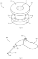
- a tympanostomy tube 1 comprises an inter flange connector 2 with a lumen 3 for crossing through a tympanic membrane.
- the inter flange connector 2 connects an outer (proximal) flange 4 and an inner (distal) flange 6.
- the distal flange 6 is around the lumen 3 at its distal end and comprises four circumferentially spaced-apart tabs 15, at 90° to each other.
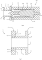
- a placement device 100 comprises a needle 104 having a stem 105 and a tip 106.
- the needle 104 extends centrally through a sleeve 107 of a stem 108 of the device 100.
- the needle stem 105 is in turn connected to a user-actuated deployment mechanism within a handle, not shown, proximally of the device stem 108.
- the mechanism is arranged to pull the needle 104 back in the proximal direction upon user pressing of an actuator button.
- This mechanism may be of any known type for user-actuated retraction, preferably spring-loaded for release of spring pressure to cause retraction.
- the retainer 120 is for holding the distal flange 6 axially for visualisation of the needle tip and to reduce the profile for insertion through the tympanic membrane in use, as described in more detail below with reference to Figs. 3 to 7 .
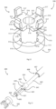
- the retainer fingers 121 pass through the proximal flange 4, surround the inter-flange connector 2, and radially push in the (folded) distal flange 6.
- the fingers 121 radially push in the tabs 15 of the distal flange 6 to an extent that the distal end of the tube 1 and the needle tip 106 can easily penetrate the tympanic membrane in use.
- the proximal flange 4 advantageously has its final in-use position at which it resists movement through the tympanic membrane, while the distal flange 6 can be easily pushed through because it is retained substantially axially by the fingers 121, the distal flange 6 tabs 15 being pressed radially inwardly.
- the tube 1 is mounted to the device 100 either manually at the point of use or is pre-mounted in the factory.
- the placement device 100 is moved by the surgeon so that the stem 108 enters the ear canal and the needle tip 106 pierces the tympanic membrane.
- the face 5 of the proximal flange 4 abuts the tympanic membrane even though the distal flange 6 is folded. This provides an accurate and simple limit to insertion of the stem 108.
- the tube proximal flange 4 extends radially beyond the distal surface of the sleeve 107, and as it abuts the tympanic membrane, it provides a reference point for visualisation when in use.
- the proximal flange 4 therefore acts as a limit to insertion, allowing the surgeon to know when the myringotomy knife (needle) 104 has been inserted far enough through the tympanic membrane and to release the tube 1 from the device 100. It is envisaged that, in other embodiments, the sleeve 107 may have a radial dimension which is even smaller relative to that of the proximal flange than illustrated.
- the passageways 10 provide radial retaining strength to the fingers 121, the radially outer surfaces 13 of the passageways 10 pressing the retainer fingers 121 inwardly at a location between the retainer base 122 and their distal ends where they press the distal flange 6 tabs 15 radially inwardly. This helps to ensure that the fingers 121 accurately and reliably retain the distal flange compressed, with the tabs 15 having an axial orientation.
- the retainer fingers 121 and the needle 104 are attached to each other and so retract together.
- the sequencing of the retainer and the needle retraction is achieved by the pulling mechanism within the placement device handle.
- a longitudinal sectional view of the tympanostomy tube 1 can be seen.
- the flange 4 is of a thicker dimension than the flange 6, and the flange 6 comprises the tabs 15 extending outwardly.
- the proximal flange 4 is of a first rigid material
- the inter-flange connector 2 and the distal flange 6 are integral and of a second, more flexible, material.
- the first material is preferably metal such as titanium
- the second material is preferably a material with shape memory properties such as Silicone or Nitinol.
- This combination of materials allows optimum strength for guiding the retainer fingers and providing structure for the tube during deployment, which prevents the tube from being pulled into the sleeve 107 during deployment, and on the other hand optimum flexibility for the distal flange to fold and release.
- Co-moulding is preferably performed for manufacture of the tube where the tube is of different materials to achieve the optimum combination of properties, with rigidity of the proximal flange for guidance of the fingers 121 and acting as a stop, and for the distal flange 6 having an ability to fold over and return to the original radial position quickly and stably.
- This rigidity of the proximal flange 4 has the added advantage of giving the tube structure during deployment.
- the tube 1 is of a flexible (implant grade silicone) material in the distal flange, and of rigid (titanium, or stainless steel) material in the remainder of the tube.
- the maximum diameter is 3mm, and the inter flange distance is 1.6mm, and the overall length is 2.7mm in this example.
- the dimensions may be of any suitable combination to suit the clinical requirements.
- a tube 201 is shown with corresponding numerals and parts to the previous embodiment of the tube 1.
- a distal flange 206 comprises two tabs 210, axially spaced apart by approximately 180°.
- the passageways of the proximal flange 4 and the device's retainer fingers are correspondingly aligned to match axially the locations of the distal flange tabs 210.
- a tube 220 is shown with corresponding numerals and parts to the embodiment of the tube 1.
- a distal flange 226 comprises three tabs 221, axially spaced apart by approximately 120°.
- a tube 230 is shown with corresponding numerals and parts to the embodiment of the tube 1.
- a distal flange 236 comprises a single annular body 231. This distal flange 236 has sufficient flexibility to be folded in by a plurality of retainer fingers.
- a tympanic membrane is often angled to vertical, typically with a slope extending upwardly and outwardly, and furthermore the membrane itself may not be planar, having a conical shape which may not be symmetrical.
- the coupler 404 and the angle of the stem allows the surgeon to choose an angle which will aid in the tympanic membrane natural angle which can be more acute depending on the anatomy of the person. This angle will allow the tube to be inserted when it is perpendicular to the tympanic membrane. This angle may or may not exist. If it is required, a bend in the stem 401 may be provided to aid better visualisation.
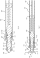
- the placement device 600 has the device stem 608 within which the needle 604 slides according to linear movement of an actuator rod 661 engaged in the needle stem 605.
- the proximal end of the needle 604 has a flange 662 for sliding engagement at the proximal end while minimising the extent of surface contact between the needle 604 and the internal surface of the stem sleeve 607.
- the device of the invention may take the form of a cartridge for connection to a third party handle or it may incorporate a handle, preferably with a mechanism for retracting the needle. Also, the mechanism for causing retraction of the needle may be of any desired type, such as for example a conventional actuator for a writing pen.
Landscapes
- Health & Medical Sciences (AREA)
- Life Sciences & Earth Sciences (AREA)
- Surgery (AREA)
- Veterinary Medicine (AREA)
- Animal Behavior & Ethology (AREA)
- Public Health (AREA)
- General Health & Medical Sciences (AREA)
- Heart & Thoracic Surgery (AREA)
- Engineering & Computer Science (AREA)
- Biomedical Technology (AREA)
- Psychology (AREA)
- Vascular Medicine (AREA)
- Acoustics & Sound (AREA)
- Otolaryngology (AREA)
- Biophysics (AREA)
- Physics & Mathematics (AREA)
- Pathology (AREA)
- Nuclear Medicine, Radiotherapy & Molecular Imaging (AREA)
- Medical Informatics (AREA)
- Molecular Biology (AREA)
- Infusion, Injection, And Reservoir Apparatuses (AREA)
- Media Introduction/Drainage Providing Device (AREA)
Applications Claiming Priority (3)
| Application Number | Priority Date | Filing Date | Title |
|---|---|---|---|
| EP17199754 | 2017-11-02 | ||
| PCT/EP2018/080015 WO2019086608A1 (fr) | 2017-11-02 | 2018-11-02 | Tube de tympanotomie et dispositif de pose |
| EP18793437.7A EP3703630B1 (fr) | 2017-11-02 | 2018-11-02 | Dispositif de pose |
Related Parent Applications (2)
| Application Number | Title | Priority Date | Filing Date |
|---|---|---|---|
| EP18793437.7A Division EP3703630B1 (fr) | 2017-11-02 | 2018-11-02 | Dispositif de pose |
| EP18793437.7A Division-Into EP3703630B1 (fr) | 2017-11-02 | 2018-11-02 | Dispositif de pose |
Publications (2)
| Publication Number | Publication Date |
|---|---|
| EP4512351A2 true EP4512351A2 (fr) | 2025-02-26 |
| EP4512351A3 EP4512351A3 (fr) | 2025-05-14 |
Family
ID=60320631
Family Applications (2)
| Application Number | Title | Priority Date | Filing Date |
|---|---|---|---|
| EP18793437.7A Active EP3703630B1 (fr) | 2017-11-02 | 2018-11-02 | Dispositif de pose |
| EP25150934.5A Pending EP4512351A3 (fr) | 2017-11-02 | 2018-11-02 | Dispositif de placement |
Family Applications Before (1)
| Application Number | Title | Priority Date | Filing Date |
|---|---|---|---|
| EP18793437.7A Active EP3703630B1 (fr) | 2017-11-02 | 2018-11-02 | Dispositif de pose |
Country Status (8)
| Country | Link |
|---|---|
| US (3) | US11547610B2 (fr) |
| EP (2) | EP3703630B1 (fr) |
| JP (1) | JP7101772B2 (fr) |
| CN (1) | CN111295165B (fr) |
| ES (1) | ES3015034T3 (fr) |
| IL (2) | IL274143B2 (fr) |
| PL (1) | PL3703630T3 (fr) |
| WO (1) | WO2019086608A1 (fr) |
Families Citing this family (6)
| Publication number | Priority date | Publication date | Assignee | Title |
|---|---|---|---|---|
| EP4051196A1 (fr) * | 2019-11-01 | 2022-09-07 | Aventamed Designated Activity Company | Drain transtympanique |
| IL292477A (en) | 2019-11-01 | 2022-06-01 | Aventamed Designated Activity Company | A tympanic membrane therapeutic device |
| EP4093355B1 (fr) | 2020-01-24 | 2025-09-24 | Spiral Therapeutics Inc. | Systèmes de traitement de la perte auditive |
| CA3194091A1 (fr) * | 2020-10-09 | 2022-04-14 | Dr. Samuel ALBERT | Tube de myringotomie a conception multi-visuelle |
| USD1064249S1 (en) | 2021-01-29 | 2025-02-25 | Samuel Albert | Myringotomy tube |
| CN117224207B (zh) * | 2023-09-06 | 2025-04-18 | 中国人民解放军总医院第一医学中心 | 一种可视性鼓膜穿刺针及其使用方法 |
Citations (4)
| Publication number | Priority date | Publication date | Assignee | Title |
|---|---|---|---|---|
| US4744792A (en) | 1985-01-22 | 1988-05-17 | Richards Medical Company | Middle ear ventilating tube |
| WO2011008948A1 (fr) | 2009-07-15 | 2011-01-20 | Acclarent, Inc. | Système de mise en place d'un tube d'équilibrage de pression de la membrane du tympan |
| WO2013113022A1 (fr) | 2012-01-29 | 2013-08-01 | Entra Tympanic, Llc | Dispositif et procédé d'insertion et de retrait de tubes de tympanostomie |
| WO2013155169A1 (fr) | 2012-04-10 | 2013-10-17 | Acclarent, Inc. | Tube d'égalisation de la pression du tympan |
Family Cites Families (15)
| Publication number | Priority date | Publication date | Assignee | Title |
|---|---|---|---|---|
| GB2204796A (en) * | 1987-05-22 | 1988-11-23 | Yale Joel Berry | Inner ear ventilation drainage |
| US5246455A (en) * | 1991-05-17 | 1993-09-21 | Micromedics, Inc. | Middle meatal antrostomy ventilation tube |
| US5207685A (en) * | 1992-02-11 | 1993-05-04 | Cinberg James Z | Tympanic ventilation tube and related technique |
| US5466239A (en) * | 1992-07-28 | 1995-11-14 | Cinberg; James Z. | Myringotomy ventilation tube and associated method |
| US7097661B2 (en) * | 2001-08-03 | 2006-08-29 | Perry Microtube Pty Ltd | Ventilation tube for a middle ear |
| GB2437708B (en) * | 2006-04-27 | 2010-05-05 | Kats Yeshayahu | Myringotomy instrument |
| CN102014795B (zh) * | 2008-02-20 | 2015-02-25 | 普利塞普提斯医药有限公司 | 通风装置和用于该通风装置的插入系统 |
| US20090299379A1 (en) * | 2008-05-28 | 2009-12-03 | Yeshayahu Katz | Myringotomy instrument |
| US8945142B2 (en) * | 2008-08-27 | 2015-02-03 | Cook Medical Technologies Llc | Delivery system for implanting nasal ventilation tube |
| CA2643179A1 (fr) * | 2008-11-06 | 2010-05-06 | Yeshayahu Katz | Instrument pour la myringotomie |
| US9770366B2 (en) * | 2009-07-15 | 2017-09-26 | Tusker Medical, Inc. | Tympanic membrane pressure equalization tube delivery system |
| FR2950526B1 (fr) * | 2009-09-25 | 2012-12-07 | Ct Hospitalier Universitaire Nimes | Systeme de drainage de l'oreille moyenne et aerateur transtympanique a cet effet |
| CN201968904U (zh) * | 2011-01-20 | 2011-09-14 | 郭萍 | 鼓膜导管安装装置 |
| US9833360B2 (en) | 2014-08-12 | 2017-12-05 | Tusker Medical, Inc. | Tympanostomy tube delivery device with replaceable shaft portion |
| US9833359B2 (en) | 2014-08-12 | 2017-12-05 | Tusker Medical, Inc. | Tympanostomy tube delivery device with cutter force clutch |
-
2018
- 2018-11-02 WO PCT/EP2018/080015 patent/WO2019086608A1/fr not_active Ceased
- 2018-11-02 PL PL18793437.7T patent/PL3703630T3/pl unknown
- 2018-11-02 EP EP18793437.7A patent/EP3703630B1/fr active Active
- 2018-11-02 CN CN201880071528.4A patent/CN111295165B/zh active Active
- 2018-11-02 ES ES18793437T patent/ES3015034T3/es active Active
- 2018-11-02 EP EP25150934.5A patent/EP4512351A3/fr active Pending
- 2018-11-02 IL IL274143A patent/IL274143B2/en unknown
- 2018-11-02 JP JP2020526108A patent/JP7101772B2/ja active Active
- 2018-11-02 IL IL308159A patent/IL308159B2/en unknown
- 2018-11-02 US US16/757,548 patent/US11547610B2/en active Active
-
2022
- 2022-11-30 US US18/071,991 patent/US12226287B2/en active Active
-
2025
- 2025-01-15 US US19/022,061 patent/US20250332034A1/en active Pending
Patent Citations (4)
| Publication number | Priority date | Publication date | Assignee | Title |
|---|---|---|---|---|
| US4744792A (en) | 1985-01-22 | 1988-05-17 | Richards Medical Company | Middle ear ventilating tube |
| WO2011008948A1 (fr) | 2009-07-15 | 2011-01-20 | Acclarent, Inc. | Système de mise en place d'un tube d'équilibrage de pression de la membrane du tympan |
| WO2013113022A1 (fr) | 2012-01-29 | 2013-08-01 | Entra Tympanic, Llc | Dispositif et procédé d'insertion et de retrait de tubes de tympanostomie |
| WO2013155169A1 (fr) | 2012-04-10 | 2013-10-17 | Acclarent, Inc. | Tube d'égalisation de la pression du tympan |
Also Published As
| Publication number | Publication date |
|---|---|
| IL308159B2 (en) | 2025-03-01 |
| WO2019086608A1 (fr) | 2019-05-09 |
| IL308159B1 (en) | 2024-11-01 |
| JP7101772B2 (ja) | 2022-07-15 |
| IL308159A (en) | 2023-12-01 |
| JP2021501661A (ja) | 2021-01-21 |
| US11547610B2 (en) | 2023-01-10 |
| EP4512351A3 (fr) | 2025-05-14 |
| EP3703630C0 (fr) | 2025-02-19 |
| IL274143B2 (en) | 2024-05-01 |
| IL274143A (en) | 2020-06-30 |
| US12226287B2 (en) | 2025-02-18 |
| CN111295165B (zh) | 2022-07-01 |
| CN111295165A (zh) | 2020-06-16 |
| ES3015034T3 (en) | 2025-04-28 |
| EP3703630B1 (fr) | 2025-02-19 |
| US20230123143A1 (en) | 2023-04-20 |
| US20250332034A1 (en) | 2025-10-30 |
| PL3703630T3 (pl) | 2025-06-09 |
| IL274143B1 (en) | 2024-01-01 |
| US20210169697A1 (en) | 2021-06-10 |
| EP3703630A1 (fr) | 2020-09-09 |
Similar Documents
| Publication | Publication Date | Title |
|---|---|---|
| US12226287B2 (en) | Tympanostomy tube and a placement device | |
| US10751219B2 (en) | Tympansostomy tube and insertion device | |
| US11806043B2 (en) | Devices and methods for providing surgical access | |
| US20240023989A1 (en) | Devices and methods for providing surgical access | |
| US5643280A (en) | Integral myringotomy tube and inserter | |
| JP2022133286A (ja) | 血管壁の穿刺部を閉鎖するための閉鎖システム | |
| JPH05115429A (ja) | トロカール・スリーブ組立体 | |
| JP2006341095A (ja) | 着脱可能な深さ止めを有する針アッセンブリ | |
| CN106456154A (zh) | 两部件式无结缝线锚 | |
| JP6632930B2 (ja) | 結紮装置用クリップユニット及び該クリップユニットの係合方法 | |
| US9320596B2 (en) | Dilator for inserting a voice prosthesis | |
| WO2020236680A1 (fr) | Dispositifs chirurgicaux et appareils de déploiement | |
| WO2001089398A1 (fr) | Systeme de canule d'acces chirurgical fiable et procedes correspondants | |
| JP2011055928A (ja) | 内視鏡用クリップ装置 |
Legal Events
| Date | Code | Title | Description |
|---|---|---|---|
| PUAI | Public reference made under article 153(3) epc to a published international application that has entered the european phase |
Free format text: ORIGINAL CODE: 0009012 |
|
| STAA | Information on the status of an ep patent application or granted ep patent |
Free format text: STATUS: THE APPLICATION HAS BEEN PUBLISHED |
|
| AC | Divisional application: reference to earlier application |
Ref document number: 3703630 Country of ref document: EP Kind code of ref document: P |
|
| AK | Designated contracting states |
Kind code of ref document: A2 Designated state(s): AL AT BE BG CH CY CZ DE DK EE ES FI FR GB GR HR HU IE IS IT LI LT LU LV MC MK MT NL NO PL PT RO RS SE SI SK SM TR |
|
| REG | Reference to a national code |
Ref country code: DE Ref legal event code: R079 Free format text: PREVIOUS MAIN CLASS: A61B0017340000 Ipc: A61F0011200000 Ref country code: DE Ref legal event code: R079 Ref document number: 602018091381 Country of ref document: DE Free format text: PREVIOUS MAIN CLASS: A61B0017340000 Ipc: A61F0011200000 |
|
| PUAL | Search report despatched |
Free format text: ORIGINAL CODE: 0009013 |
|
| AK | Designated contracting states |
Kind code of ref document: A3 Designated state(s): AL AT BE BG CH CY CZ DE DK EE ES FI FR GB GR HR HU IE IS IT LI LT LU LV MC MK MT NL NO PL PT RO RS SE SI SK SM TR |
|
| RIC1 | Information provided on ipc code assigned before grant |
Ipc: A61B 17/34 20060101ALI20250410BHEP Ipc: A61F 11/20 20220101AFI20250410BHEP |
|
| STAA | Information on the status of an ep patent application or granted ep patent |
Free format text: STATUS: REQUEST FOR EXAMINATION WAS MADE |
|
| 17P | Request for examination filed |
Effective date: 20251104 |
|
| GRAP | Despatch of communication of intention to grant a patent |
Free format text: ORIGINAL CODE: EPIDOSNIGR1 |
|
| STAA | Information on the status of an ep patent application or granted ep patent |
Free format text: STATUS: GRANT OF PATENT IS INTENDED |
|
| RIC1 | Information provided on ipc code assigned before grant |
Ipc: A61F 11/20 20220101AFI20251121BHEP Ipc: A61B 17/34 20060101ALI20251121BHEP |
|
| INTG | Intention to grant announced |
Effective date: 20251210 |
|
| RAP1 | Party data changed (applicant data changed or rights of an application transferred) |
Owner name: KARL STORZ SE & CO. KG |
|
| GRAS | Grant fee paid |
Free format text: ORIGINAL CODE: EPIDOSNIGR3 |
|
| GRAA | (expected) grant |
Free format text: ORIGINAL CODE: 0009210 |
|
| STAA | Information on the status of an ep patent application or granted ep patent |
Free format text: STATUS: THE PATENT HAS BEEN GRANTED |
|
| P01 | Opt-out of the competence of the unified patent court (upc) registered |
Free format text: CASE NUMBER: UPC_APP_0009257_4512351/2026 Effective date: 20260310 |