EP4512509A1 - Procédé à membrane à basse température pour valorisation de biogaz - Google Patents
Procédé à membrane à basse température pour valorisation de biogaz Download PDFInfo
- Publication number
- EP4512509A1 EP4512509A1 EP24196214.1A EP24196214A EP4512509A1 EP 4512509 A1 EP4512509 A1 EP 4512509A1 EP 24196214 A EP24196214 A EP 24196214A EP 4512509 A1 EP4512509 A1 EP 4512509A1
- Authority
- EP
- European Patent Office
- Prior art keywords
- stream
- stage
- gas stream
- permeate
- membrane
- Prior art date
- Legal status (The legal status is an assumption and is not a legal conclusion. Google has not performed a legal analysis and makes no representation as to the accuracy of the status listed.)
- Pending
Links
Images
Classifications
-
- C—CHEMISTRY; METALLURGY
- C10—PETROLEUM, GAS OR COKE INDUSTRIES; TECHNICAL GASES CONTAINING CARBON MONOXIDE; FUELS; LUBRICANTS; PEAT
- C10L—FUELS NOT OTHERWISE PROVIDED FOR; NATURAL GAS; SYNTHETIC NATURAL GAS OBTAINED BY PROCESSES NOT COVERED BY SUBCLASSES C10G OR C10K; LIQUIFIED PETROLEUM GAS; USE OF ADDITIVES TO FUELS OR FIRES; FIRE-LIGHTERS
- C10L3/00—Gaseous fuels; Natural gas; Synthetic natural gas obtained by processes not covered by subclass C10G, C10K; Liquefied petroleum gas
- C10L3/06—Natural gas; Synthetic natural gas obtained by processes not covered by C10G, C10K3/02 or C10K3/04
- C10L3/10—Working-up natural gas or synthetic natural gas
- C10L3/101—Removal of contaminants
- C10L3/102—Removal of contaminants of acid contaminants
- C10L3/104—Carbon dioxide
-
- C—CHEMISTRY; METALLURGY
- C10—PETROLEUM, GAS OR COKE INDUSTRIES; TECHNICAL GASES CONTAINING CARBON MONOXIDE; FUELS; LUBRICANTS; PEAT
- C10L—FUELS NOT OTHERWISE PROVIDED FOR; NATURAL GAS; SYNTHETIC NATURAL GAS OBTAINED BY PROCESSES NOT COVERED BY SUBCLASSES C10G OR C10K; LIQUIFIED PETROLEUM GAS; USE OF ADDITIVES TO FUELS OR FIRES; FIRE-LIGHTERS
- C10L3/00—Gaseous fuels; Natural gas; Synthetic natural gas obtained by processes not covered by subclass C10G, C10K; Liquefied petroleum gas
- C10L3/06—Natural gas; Synthetic natural gas obtained by processes not covered by C10G, C10K3/02 or C10K3/04
- C10L3/10—Working-up natural gas or synthetic natural gas
-
- B—PERFORMING OPERATIONS; TRANSPORTING
- B01—PHYSICAL OR CHEMICAL PROCESSES OR APPARATUS IN GENERAL
- B01D—SEPARATION
- B01D53/00—Separation of gases or vapours; Recovering vapours of volatile solvents from gases; Chemical or biological purification of waste gases, e.g. engine exhaust gases, smoke, fumes, flue gases, aerosols
- B01D53/002—Separation of gases or vapours; Recovering vapours of volatile solvents from gases; Chemical or biological purification of waste gases, e.g. engine exhaust gases, smoke, fumes, flue gases, aerosols by condensation
-
- B—PERFORMING OPERATIONS; TRANSPORTING
- B01—PHYSICAL OR CHEMICAL PROCESSES OR APPARATUS IN GENERAL
- B01D—SEPARATION
- B01D53/00—Separation of gases or vapours; Recovering vapours of volatile solvents from gases; Chemical or biological purification of waste gases, e.g. engine exhaust gases, smoke, fumes, flue gases, aerosols
- B01D53/22—Separation of gases or vapours; Recovering vapours of volatile solvents from gases; Chemical or biological purification of waste gases, e.g. engine exhaust gases, smoke, fumes, flue gases, aerosols by diffusion
- B01D53/225—Multiple stage diffusion
- B01D53/226—Multiple stage diffusion in serial connexion
-
- B—PERFORMING OPERATIONS; TRANSPORTING
- B01—PHYSICAL OR CHEMICAL PROCESSES OR APPARATUS IN GENERAL
- B01D—SEPARATION
- B01D53/00—Separation of gases or vapours; Recovering vapours of volatile solvents from gases; Chemical or biological purification of waste gases, e.g. engine exhaust gases, smoke, fumes, flue gases, aerosols
- B01D53/22—Separation of gases or vapours; Recovering vapours of volatile solvents from gases; Chemical or biological purification of waste gases, e.g. engine exhaust gases, smoke, fumes, flue gases, aerosols by diffusion
- B01D53/225—Multiple stage diffusion
- B01D53/227—Multiple stage diffusion in parallel connexion
-
- B—PERFORMING OPERATIONS; TRANSPORTING
- B01—PHYSICAL OR CHEMICAL PROCESSES OR APPARATUS IN GENERAL
- B01D—SEPARATION
- B01D63/00—Apparatus in general for separation processes using semi-permeable membranes
- B01D63/02—Hollow fibre modules
-
- B—PERFORMING OPERATIONS; TRANSPORTING
- B01—PHYSICAL OR CHEMICAL PROCESSES OR APPARATUS IN GENERAL
- B01D—SEPARATION
- B01D71/00—Semi-permeable membranes for separation processes or apparatus characterised by the material; Manufacturing processes specially adapted therefor
- B01D71/06—Organic material
-
- C—CHEMISTRY; METALLURGY
- C07—ORGANIC CHEMISTRY
- C07C—ACYCLIC OR CARBOCYCLIC COMPOUNDS
- C07C7/00—Purification; Separation; Use of additives
- C07C7/005—Processes comprising at least two steps in series
-
- C—CHEMISTRY; METALLURGY
- C07—ORGANIC CHEMISTRY
- C07C—ACYCLIC OR CARBOCYCLIC COMPOUNDS
- C07C7/00—Purification; Separation; Use of additives
- C07C7/144—Purification; Separation; Use of additives using membranes, e.g. selective permeation
-
- B—PERFORMING OPERATIONS; TRANSPORTING
- B01—PHYSICAL OR CHEMICAL PROCESSES OR APPARATUS IN GENERAL
- B01D—SEPARATION
- B01D2256/00—Main component in the product gas stream after treatment
- B01D2256/24—Hydrocarbons
- B01D2256/245—Methane
-
- B—PERFORMING OPERATIONS; TRANSPORTING
- B01—PHYSICAL OR CHEMICAL PROCESSES OR APPARATUS IN GENERAL
- B01D—SEPARATION
- B01D2257/00—Components to be removed
- B01D2257/50—Carbon oxides
- B01D2257/504—Carbon dioxide
-
- B—PERFORMING OPERATIONS; TRANSPORTING
- B01—PHYSICAL OR CHEMICAL PROCESSES OR APPARATUS IN GENERAL
- B01D—SEPARATION
- B01D2257/00—Components to be removed
- B01D2257/80—Water
-
- B—PERFORMING OPERATIONS; TRANSPORTING
- B01—PHYSICAL OR CHEMICAL PROCESSES OR APPARATUS IN GENERAL
- B01D—SEPARATION
- B01D2258/00—Sources of waste gases
- B01D2258/05—Biogas
-
- C—CHEMISTRY; METALLURGY
- C10—PETROLEUM, GAS OR COKE INDUSTRIES; TECHNICAL GASES CONTAINING CARBON MONOXIDE; FUELS; LUBRICANTS; PEAT
- C10L—FUELS NOT OTHERWISE PROVIDED FOR; NATURAL GAS; SYNTHETIC NATURAL GAS OBTAINED BY PROCESSES NOT COVERED BY SUBCLASSES C10G OR C10K; LIQUIFIED PETROLEUM GAS; USE OF ADDITIVES TO FUELS OR FIRES; FIRE-LIGHTERS
- C10L2290/00—Fuel preparation or upgrading, processes or apparatus therefore, comprising specific process steps or apparatus units
- C10L2290/54—Specific separation steps for separating fractions, components or impurities during preparation or upgrading of a fuel
- C10L2290/548—Membrane- or permeation-treatment for separating fractions, components or impurities during preparation or upgrading of a fuel
Definitions
- Multi-stage membrane systems are known for upgrading raw biogas streams into high purity methane streams.
- Current upgrading systems generate a pressurized feed gas stream by supplying a gas stream to a compressor.
- the compressed gas stream is fed to subsequent membrane separation stages where it is separated into a non-permeate stream that is enriched in a slow gas and a permeate stream that is enriched in a fast gas to recover a final product stream having a high concentration of the slow non-permeating gas, such as methane.
- Membrane systems often operate at ambient or warmer temperatures chosen to provide a few degrees of superheat to prevent condensation on the membrane materials.
- Such multi-stage membrane systems can achieve high methane recovery and purity, but often require relatively high capital expenditures (CapEx) associated with high membrane areas (or counts), and high operational expenditures (OpEx) associated with high compressor power costs. Also, operating expenditures for such current upgrading systems can be relatively high due to high recycle flow rates requiring larger and more expensive compressors.
- the disclosed embodiments satisfy the need in the art by providing a multi-stage membrane method and system for methane recovery from biogas that reduces the overall cost of ownership and operation. It has been found that systems having polymeric membranes with high carbon dioxide ("CO2") permeability, low CO2 activation energy, and high methane (“CH4") activation energy can be operated at low temperature to exploit the higher CO2/CH4 selectivity while maintaining a high CO2 permeability, which may displace some high selectivity membranes that typically have a low CO2 permeability. In this manner, recycle flow is reduced (which reduces required compressor power) and membrane counts are reduced. Also, to protect the separation membranes from liquid condensation, a chiller and membrane drying stage are provided upstream from the separation membranes. The membrane drying stage may be swept with a portion of a recycled gas from one of the separation membranes. This design flexibility is not available to current separation membrane systems having minimal temperature sensitivity.
- CO2 carbon dioxide
- CH4 methane
- a method comprising:
- Aspect 2 The method of Aspect 1, wherein the target operating temperature is between 3 and 7 degrees C.
- Aspect 3 The method of Aspect 1, wherein the target operating temperature is about 5 degrees C.
- Aspect 4 The method of Aspect 1, wherein the feed gas stream comprises at least 40% CH4.
- Aspect 5 The method of Aspect 1, wherein each of the at least one first stage membrane module has a first stage CO2/CH4 selectivity that is greater than a second stage CO2/CH4 selectivity of each of the at least one second stage membrane module and a third stage CO2/CH4 selectivity of each of the at least one third stage membrane module.
- Aspect 6 The method of Aspect 1, wherein each of the at least one first stage membrane module has a first stage CO2/CH4 selectivity greater than 30 at the target operating temperature.
- Aspect 7 The method of Aspect 1, wherein each of the at least one second stage membrane module has a CO2/CH4 selectivity greater than 20 at the target operating temperature.
- Aspect 8 The method of Aspect 1, wherein each of the at least one first stage membrane module comprises a polymer membrane having a first capacity, and wherein each of the at least one second stage membrane module and each of the at least one third stage membrane module comprises a polymer membrane having a capacity that is greater than the first capacity.
- Aspect 9 The method of Aspect 1, wherein each of the at least one first stage membrane module comprises a polymer membrane having a first selectivity, and wherein each of the at least one second stage membrane module and each of the at least one third stage membrane module comprises a polymer membrane having a selectivity that is less than the first selectivity.
- Aspect 10 The method of Aspect 1, wherein step (j) comprises combining the third non-permeate stream, the water vapor permeate stream, and the first portion of the sweep gas stream to form a recycle stream.
- Aspect 11 The method of Aspect 1, further comprising: (k) controlling a flow split between the first portion of the sweep gas stream from the sweep gas stream.
- Aspect 12 The method of Aspect 1, wherein the second non-permeate stream comprises CO2 within a range between about 0.5% and about 5%.
- a system comprising:
- Aspect 14 The system of Aspect 13, additionally comprising a second mixing junction for optionally combining a first portion of the sweep gas stream with the third non-permeate stream.
- Aspect 15 The system of Aspect 13, wherein the target operating temperature is between 3 and 7 degrees C.
- Aspect 16 The system of Aspect 13, wherein the target operating temperature is approximately 5 degrees C.
- Aspect 17 The system of Aspect 13, wherein the feed gas stream comprises at least 40% CH4.
- Aspect 18 The system of Aspect 13, wherein the second non-permeate stream comprises CO2 within a range between about 0.5% and about 5%.
- Aspect 19 The system of Aspect 13, wherein the sweep gas stream is fed in a direction of flow that is countercurrent to the direction of flow in which the saturated gas stream is fed into the at least one membrane dryer.
- directional terms may be used in the specification and claims to describe portions of the present invention (e.g., upper, lower, left, right, etc.). These directional terms are merely intended to assist in describing and claiming the invention and are not intended to limit the invention in any way.
- reference numerals that are introduced in the specification in association with a drawing figure may be repeated in one or more subsequent figures without additional description in the specification in order to provide context for other features.
- biomass means a renewable fuel produced by the breakdown of organic matter, including without limitation food scraps and animal waste.
- membrane module means a device that is used to selectively separate gases by flowing, at a relatively high pressure, a feed gas through one or more conduits contained within a shell (also referred to as a high pressure side).
- the conduits are at least partially defined by a membrane material that provides a barrier between each conduit and a shell space (also referred to as a low pressure side).
- the shell space is an internal volume within the shell and external to each of the membranes that is maintained at a relatively low pressure.
- the shell side is in fluid flow communication with a permeate port, through which gas that permeates the membrane(s) exits the shell.
- a sweep port may also be provided, which supplies a sweep gas to the shell space and assists the flow of permeate gas through the permeate port.
- the membrane material is chosen to enable one or more gases in the feed stream to pass through the membrane material at a higher rate than other gas(es) in the feed stream.
- the membrane module may be of a bore-side feed design wherein the membrane module is pressurized by introduction of a feed gas stream into its bore side or may be of a shell-side feed design wherein the membrane module is pressurized by introduction of the feed gas stream into its shell side.
- wash gas means a stream of gas which is supplied to the low pressure side of a membrane and dilutes the concentration of the fast-permeating gas in the permeate stream, reducing its partial pressure and increasing the driving force for separation.
- off-gas means a gas which is given off, especially one emitted as the byproduct of a chemical process.
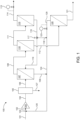
- FIG. 1 shows an exemplary embodiment of a three-stage membrane separation system 100, which includes a feed compressor 103, a chiller 105, a membrane drying stage 107, and three membrane separation stages 110, 113, and 120.
- a raw feed gas stream 101 typically comprises carbon dioxide (CO2) and methane (CH4) as major constituents, often along with other minor constituents such as oxygen (O2), nitrogen (N2), and water (H2O).
- CO2 carbon dioxide
- CH4 methane
- Membranes used in system 100 are typically selective for CO2 over CH4, meaning that CO2 is considered a fast-permeating gas that preferentially crosses the membrane at a relatively high rate, while CH4 is a slow permeating gas that crosses the membrane at a relatively low rate.
- Gas permeability through a membrane is governed by the solution-diffusion transport mechanism where the permeation rate is a function of the molecular size (diffusivity) and the molecular solubility in the polymer and is proportional to the driving force.
- the driving force for gas separation is the partial pressure differential of the permeating species between the high-pressure and low-pressure sides of the membrane.
- the gas permeability of each gaseous component of a gas mixture will typically be different, and the partial pressure of each gaseous component will be proportional to its relative concentration in the gas mixture as well as the total pressure of the gas mixture.
- a recycle stream 125 is mixed into the raw feed gas stream 101 at a mixing junction 122 to form a combined feed stream 102.
- the raw feed gas stream may be or comprise a biogas stream, and may be obtained from a number of sources such as a raw biogas stream resulting from a fermentation process.
- the raw feed gas stream may also be obtained from a landfill.
- a typical biogas raw feed gas stream would comprise about 40-70% CH4, about 30-60% CO2, would be nearly or fully saturated with water vapor, and would comprise low concentrations of hydrogen sulfide (0-5000 ppm), nitrogen (0-20%), and oxygen (0-5%).
- the combined feed stream 102 is compressed to a pressure that is within a range of between about 7-35 Barg in a feed compressor 103 to yield a pressurized combined feed stream 104.
- the combined feed stream 102 may be compressed to a pressure of about 14 Barg.
- the pressurized combined feed stream 104 is fed into a chiller 105 which lowers the pressurized combined feed stream 104 temperature to a target operating temperature.
- the target operating temperature may be between about 0- and 20-degrees C. Alternatively, the target operating temperature may be between about 3 and 7 degrees C or about 5 degrees C.
- the chiller 105 may include its own refrigeration unit that cools a circulating chiller fluid or may be cooled by indirect heat exchange provided by a refrigerant. Lowering the temperature of the combined feed stream lowers the dew point at the same pressure by forming a condensed water stream 127, resulting in a chilled saturated gas stream 106.
- Lowering the feed temperature of the pressurized combined feed stream 104 also enables the membrane stages 110, 113, and 120 to operate with more favorable selectivity.
- the condensed water stream 127 may optionally be collected and drained to a condensate drain (not shown).
- the chilled saturated gas stream 106 is then supplied to a membrane drying stage 107, which removes water vapor from the chilled saturated gas stream 106 by selective permeation of water molecules through a polymer membrane located within the membrane drying stage 107.
- a suitable membrane dryer may be one such as Air Products Membrane Solutions PRISM ® GreenDry Flex, which eliminates the need to heat the stream above its dewpoint.
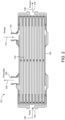
- the membrane drying stage 107 comprises a generally cylindrical-shaped shell or housing 126, a feed port 130 located at a first end of the shell 126 and a non-permeate port 134 located at a second end of the shell 126 opposite the first end.
- the membrane drying stage 107 also includes a permeate port 138 and a sweep port 142 located along the side wall of the shell 126.
- the sweep port 142 is shown as being located on the same side of the shell 126 as the permeate port 138. This location is merely exemplary and the location of the sweep port 142 as shown in FIG. 2 should not be limiting.
- the sweep port 142 may be positioned at other locations on the shell 126.
- the sweep port 142 may be positioned on the side of the shell 126 opposite the permeate port 138, e.g., to the right of the numeral 126 in FIG. 2 , to improve sweep efficiency.
- the length of the shell 126 as shown in FIG. 2 is merely exemplary and should not be limiting. The shell could be provided in a length that is less than that of the membrane stages 110, 113, and 120.
- the membrane drying stage 107 includes selectively permeable membrane fibers 144 housed within the shell 126 that serve as a molecular filter where water vapor in the chilled saturated gas stream 106 travels across a membrane faster than other gas molecules and exits the membrane drying stage through the permeate port 138 as a water vapor stream 109.
- the drying stage 107 must be highly selective to water in the chilled saturated gas stream 106 over other gas components.
- the membrane fibers 144 may consist of a bundle of hollow fibers with the ends potted in epoxy or other resin. The bundle of the membrane fibers 144 is enclosed within the shell 126 which protects the membrane and routes the gas properly.
- the chilled saturated gas stream 106 flows into the feed port 130 and along a high-pressure side (or "feed” side) of the membrane drying stage 107, the water vapor permeates through the walls of the membrane fibers 144 to a low-pressure side (or “permeate” side) and exits the membrane drying stage 107 through the permeate port 138 as the water vapor stream 109.
- the water vapor content of the chilled saturated gas stream 106 becomes progressively lower as the chilled saturated gas stream 106 flows along the length of the membrane drying stage 107 from the feed port 130 to the non-permeate port 134.
- a low pressure sweep gas stream 119 may be injected into the sweep port 142 to sweep the permeate side of the membrane drying stage 107 to increase the driving force for water permeation.
- a dried gas stream 108 exits the non-permeate port 134 of the membrane drying stage 107.
- the dried gas stream 108 may have a water content preferably within a range of about 200-500 ppm, but also may have a water content of approximately 1000 ppm, or even approximately 2000 ppm.
- the effect of the membrane drying stage 107 on the composition of the dried gas stream 108 is minimal, e.g., less than 0.5 mol% change in CO2 is expected.
- the dried gas stream 108 is supplied to a first membrane stage 110.
- a stream comprising primarily fast permeating gas permeates and exits the first membrane stage 110 as a first stage permeate stream 112.
- a stream comprising primarily slow permeating gases is rejected and withdrawn as a first stage non-permeate stream 111.
- CO2 would permeate much more rapidly than CH4.
- the first membrane stage 110 may include membranes exhibiting a high selectivity, but low capacity (where capacity is defined as the product of membrane permeance and active membrane area). Studies have determined that a trade-off in behavior exists between permeability and selectivity ( L.M. Robeson, J. Membr.
- the first membrane stage may include membranes using a polymer with a CO2 permeability between 0.5 and 3 Barrers, and a CO2/CH4 selectivity within a range of 30-60 at the target operating temperature (membrane type "A").
- the first membrane stage 110 may include one or more membrane modules, with multiple membranes being arranged in series or parallel.
- the first stage non-permeate stream 111 is supplied to a second membrane stage 113.
- the second membrane stage 113 may include membranes exhibiting high capacity but low selectivity when used at standard operating temperatures such as 30 degrees C.
- the second membrane stage may include gas separation membranes using a polymer having a CO2 permeability between 5 and 50 Barrers, and a CO2/CH4 selectivity within a range of 20 to 30 at standard warmer operating conditions (membrane type "B").
- a stream comprising primarily slow permeating gases may be rejected and withdrawn as a second stage non-permeate stream 114.
- the second stage non-permeate stream 114 may be withdrawn from the system 100 utilizing a pressure control valve 115 as a final product stream.
- a stream comprising primarily fast permeating gases permeates and exits the second membrane stage 113 as a second stage permeate stream 116.
- a portion of the second stage permeate stream 116 may be returned to the membrane drying stage 107 and utilized as the low pressure sweep gas stream 119.
- a control valve 117 may be provided to control the flow of the low pressure sweep gas stream 119 into the sweep port 142.
- the remaining portion of the second stage permeate stream 118 may be returned to a point upstream of the feed compressor 103 to be recycled through the system.
- the second membrane stage 113 may include one or more membrane modules, with multiple membranes being arranged in series or parallel.
- the first stage permeate stream 112 may be supplied to a third membrane stage 120.
- the third membrane stage 120 serves as the final step for collecting methane, so it is important to include membranes in this stage that are highly selective.
- such highly selective membranes usually also have low capacity, thus requiring a large membrane count (number of membranes) in the third membrane stage 120.
- a membrane type exhibiting high capacity, typically low selectivity, and also a low CO2 activation energy may be substituted for the membrane exhibiting high selectivity but low capacity.
- the third membrane stage 120 may include gas separation membranes of membrane type "B" having a CO2 activation energy within a range of about 1000 to 3000 cal/mol and a CH4 activation energy about 5000 cal/mol.
- This membrane type responds well to a lower operating temperature to achieve a higher selectivity, while substantially maintaining capacity as if operating at a higher temperature. This favorable response to low temperature can only occur if the CO2 activation energy is low and the CH4 activation energy is high.
- the number and cost of membranes utilized in the third membrane stage 120 can be substantially reduced.
- the recycle/feed ratio can be substantially reduced thus decreasing the flow rate of the recycle stream 125 and increasing overall process efficiency.
- a stream comprising primarily fast permeating gases permeates the membrane and exits the third membrane stage 120 as a third stage permeate stream 121 which may be a vented stream or waste stream.
- a stream comprising primarily slow permeating gases may be withdrawn as a third stage non-permeate stream 129.
- the third stage non-permeate stream 129 exits the third membrane stage 120 via a pressure control valve 123 and may be combined with the remaining portion of the second stage permeate stream 118 and the water vapor stream 109 into a single recycle stream 125 and returned to a point upstream of the feed compressor 103 to be recycled through the system 100.
- the third stage non-permeate stream 129 has a higher concentration of CO2 than CH4 because the third membrane stage 120 is being fed with the first stage permeate stream 112, which comprises 90-95 mol% CO2.
- the third membrane stage 120 may contain one or more membranes, with multiple membranes being arranged in series or parallel.
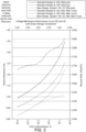
- FIG. 3 is a graph showing modeled performance curves of two "standard design” (identified as “Standard Design A” and “Standard Design B”) biogas separation systems (i.e., without a membrane drying stage stage) operated at 20 degrees C, and the biogas separation system 100 of the present invention ("New Design") including the membrane drying stage 107 and operated at 5 degrees C.
- the Standard Design A is a system of conventional design including a first membrane stage comprising membranes of type "A" (high selectivity/low capacity), a second membrane stage comprising membranes of type “B” (low selectivity/high capacity), and a third membrane stage having membranes of type "A” (high selectivity/low capacity).
- the Standard Design B is also of conventional design wherein all three membrane stages include membranes of type "A" (high selectivity/low capacity). All of the simulations were performed using the following operating parameters: a feed gas composition of 60% CH4 and 40% CO2 on a dry basis that is saturated with water vapor, the feed gas stream being compressed by the feed compressor 103 to a pressure of 14 Barg, and the feed gas stream being supplied at a flow rate of 1000 normal cubic meters per hour (ncmh).
- the target CH4 recovery for the system was 99.5%, where CH4 recovery is defined as the amount of methane in the product stream (in system 100, the second stage non-permeate stream 114) divided by the amount of methane in the feed gas stream (in system 100, the raw feed gas stream 101).
- Each of the simulated systems includes two curves on the graph.
- the first curve for each simulated system shows the membrane cost factor.
- the membrane cost factor for Standard Design A has been normalized to a value of 1.00 to enable comparison with the membrane cost factor for the Standard Design B and the membrane cost factor for the biogas separation system 100 of the present invention.
- Fig. 3 demonstrates that the New Design achieves the 99.5% CH4 target product recovery while lowering the relative membrane cost for most of the CO2 percentages in the product gas stream when compared with Standard Design A and for all of the CO2 percentages in the product gas stream when compared with Standard Design B.
- the membrane costs are also set forth in Table 1 below.
- the second curve for each simulated system is the applicable recycle/feed ratio (recycle stream 125 to feed gas stream 101 ratio) as a function of product gas purity (e.g., %CO2 in the second stage non-permeate stream 114).
- product gas purity e.g., %CO2 in the second stage non-permeate stream 114.
- the New Design achieves the 99.5% CH4 target product recovery while reducing recycle flow (which lowers required compressor power) when compared with the standard design systems, i.e., Standard Design A and Standard Design B.
- the lower operating temperature of the New Design allows for increased use of high-capacity polymer membranes having low CO2 activation energy in the membrane separation stages. When operated at lower temperature, the high-capacity membranes gained selectivity, and unexpectedly sacrificed very little capacity.
- the recycle/feed ratios are also set forth in Table 1.
- the membrane cost, system capital expense, and estimated 10-year cost of ownership are provided for the Standard Design A, the Standard Design B, and the New Design for different CO2 percentages in the product gas stream (second stage non-permeate stream 114).
- These cost and expense values have been normalized to a value of 1.00 for the Standard Design A to enable comparison with the performance of Standard Design B and the biogas separation system 100. Normalizing is achieved by dividing each value for the system 100 and for the Standard Design B by the corresponding value from the Standard Design A which is the reference so that the values for the New Design and the Standard Design B are expressed as a factor of the corresponding values for the Standard Design A.
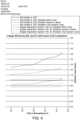
- FIG 4 also shows a modeled 10-year cost of ownership of an exemplary implementation of the New Design system versus the two Standard Design systems for different CO2 percentages in the product gas stream (second stage non-permeate stream 114). As demonstrated by FIG.
- the New Design system provides a substantially lower expected cost of ownership over a ten-year expected life of the system than either of the Standard Design systems. As energy costs continue to rise, it is expected that the biogas separation system of the present invention will further reduce relative operating expenses.
Landscapes
- Chemical & Material Sciences (AREA)
- Oil, Petroleum & Natural Gas (AREA)
- Organic Chemistry (AREA)
- Engineering & Computer Science (AREA)
- Chemical Kinetics & Catalysis (AREA)
- Analytical Chemistry (AREA)
- General Chemical & Material Sciences (AREA)
- Water Supply & Treatment (AREA)
- Separation Using Semi-Permeable Membranes (AREA)
Applications Claiming Priority (1)
| Application Number | Priority Date | Filing Date | Title |
|---|---|---|---|
| US18/237,000 US12365640B2 (en) | 2023-08-23 | 2023-08-23 | Low temperature membrane process for biogas upgrading |
Publications (1)
| Publication Number | Publication Date |
|---|---|
| EP4512509A1 true EP4512509A1 (fr) | 2025-02-26 |
Family
ID=92538651
Family Applications (1)
| Application Number | Title | Priority Date | Filing Date |
|---|---|---|---|
| EP24196214.1A Pending EP4512509A1 (fr) | 2023-08-23 | 2024-08-23 | Procédé à membrane à basse température pour valorisation de biogaz |
Country Status (8)
| Country | Link |
|---|---|
| US (2) | US12365640B2 (fr) |
| EP (1) | EP4512509A1 (fr) |
| JP (1) | JP7902885B2 (fr) |
| KR (1) | KR20250029749A (fr) |
| CN (1) | CN119505964A (fr) |
| AU (1) | AU2024205864A1 (fr) |
| CA (1) | CA3244800A1 (fr) |
| IL (1) | IL315085A (fr) |
Families Citing this family (4)
| Publication number | Priority date | Publication date | Assignee | Title |
|---|---|---|---|---|
| EP4074409A1 (fr) * | 2021-04-13 | 2022-10-19 | Linde GmbH | Procédé de réduction de la teneur en dioxyde de carbone d'un mélange gazeux et agencement de séparation de membrane |
| EP4724183A2 (fr) * | 2023-06-07 | 2026-04-15 | Alchemy CO2, PBC | Systèmes et procédés de traitement de gaz naturel renouvelable |
| WO2024254503A2 (fr) | 2023-06-07 | 2024-12-12 | Alchemy Co2, Pbc | Systèmes et procédés de traitement de gaz naturel renouvelable |
| US12654126B2 (en) * | 2024-01-16 | 2026-06-16 | Air Products And Chemicals, Inc. | 4-stage membrane process with sweep for biogas upgrading |
Citations (5)
| Publication number | Priority date | Publication date | Assignee | Title |
|---|---|---|---|---|
| EP0647463A1 (fr) * | 1993-10-12 | 1995-04-12 | PRAXAIR TECHNOLOGY, Inc. | Procédé pour le démarrage et l'arrêt des systèmes de membranes |
| US20130098242A1 (en) * | 2010-07-01 | 2013-04-25 | Evonik Fibres Gmbh | Process for separation of gases |
| US20170198227A1 (en) * | 2014-09-18 | 2017-07-13 | Korea Research Institute Of Chemical Technology | Multistage Membrane Separation and Purification Process and Apparatus for Separating High Purity Methane Gas |
| US20170304769A1 (en) * | 2014-09-03 | 2017-10-26 | L'air Liquide, Societe Anonyme Pour I'etude Et I'exploitation Des Procedes Georges Claude | Method for purifying biogas through membranes at negative temperatures |
| US20210283548A1 (en) * | 2018-08-08 | 2021-09-16 | L'air Liquide, Societe Anonyme Pour L'etude Et L'exploitation Des Procedes Georges Claude | Membrane permeation treatment with adjustment of the temperature of the first retentate as a function of the ch4 concentration in the third and/or fourth permeate |
Family Cites Families (11)
| Publication number | Priority date | Publication date | Assignee | Title |
|---|---|---|---|---|
| JPH04180812A (ja) * | 1990-11-16 | 1992-06-29 | Nkk Corp | 水蒸気及び炭酸ガスの除去方法 |
| US5169412A (en) * | 1991-11-20 | 1992-12-08 | Praxair Technology Inc. | Membrane air drying and separation operations |
| US5259869A (en) | 1992-05-06 | 1993-11-09 | Permea, Inc. | Use of membrane separation to dry gas streams containing water vapor |
| US8317899B2 (en) | 2009-11-10 | 2012-11-27 | Generon Igs, Inc. | Shipboard hybrid system for making dry, oil-free, utility air and inert gas |
| JP5948853B2 (ja) | 2011-12-20 | 2016-07-06 | 宇部興産株式会社 | ガス分離システム |
| JP6435961B2 (ja) | 2014-03-31 | 2018-12-12 | 宇部興産株式会社 | ガス分離システム及び富化ガスの製造方法 |
| MY180042A (en) | 2014-12-29 | 2020-11-20 | Evonik Fibres Gmbh | Process for separation of gases with reduced maintenance costs |
| US10005023B2 (en) | 2015-03-25 | 2018-06-26 | Praxair Technology, Inc. | Method and system for CO2 rejection with a two stage membrane process |
| US9969949B1 (en) | 2016-10-20 | 2018-05-15 | Iogen Corporation | Method and system for providing upgraded biogas |
| EP3632525A1 (fr) | 2018-10-02 | 2020-04-08 | Evonik Fibres GmbH | Dispositif et procédé permettant de séparer le méthane d'un mélange gazeux contenant du méthane, du dioxyde de carbone et du sulfure d'hydrogène |
| US20220203294A1 (en) | 2020-12-31 | 2022-06-30 | Air Liquide Advanced Technologies Us Llc | Three stage membrane gas separation with cooling and use of sweep gas |
-
2023
- 2023-08-23 US US18/237,000 patent/US12365640B2/en active Active
-
2024
- 2024-08-19 IL IL315085A patent/IL315085A/en unknown
- 2024-08-19 AU AU2024205864A patent/AU2024205864A1/en active Pending
- 2024-08-21 KR KR1020240112046A patent/KR20250029749A/ko active Pending
- 2024-08-21 CN CN202411149216.4A patent/CN119505964A/zh active Pending
- 2024-08-21 CA CA3244800A patent/CA3244800A1/en active Pending
- 2024-08-22 JP JP2024140603A patent/JP7902885B2/ja active Active
- 2024-08-23 EP EP24196214.1A patent/EP4512509A1/fr active Pending
-
2025
- 2025-04-15 US US19/179,019 patent/US20260159462A1/en active Pending
Patent Citations (5)
| Publication number | Priority date | Publication date | Assignee | Title |
|---|---|---|---|---|
| EP0647463A1 (fr) * | 1993-10-12 | 1995-04-12 | PRAXAIR TECHNOLOGY, Inc. | Procédé pour le démarrage et l'arrêt des systèmes de membranes |
| US20130098242A1 (en) * | 2010-07-01 | 2013-04-25 | Evonik Fibres Gmbh | Process for separation of gases |
| US20170304769A1 (en) * | 2014-09-03 | 2017-10-26 | L'air Liquide, Societe Anonyme Pour I'etude Et I'exploitation Des Procedes Georges Claude | Method for purifying biogas through membranes at negative temperatures |
| US20170198227A1 (en) * | 2014-09-18 | 2017-07-13 | Korea Research Institute Of Chemical Technology | Multistage Membrane Separation and Purification Process and Apparatus for Separating High Purity Methane Gas |
| US20210283548A1 (en) * | 2018-08-08 | 2021-09-16 | L'air Liquide, Societe Anonyme Pour L'etude Et L'exploitation Des Procedes Georges Claude | Membrane permeation treatment with adjustment of the temperature of the first retentate as a function of the ch4 concentration in the third and/or fourth permeate |
Non-Patent Citations (1)
| Title |
|---|
| L.M. ROBESON, J. MEMBR. SCI., vol. 320, 2008, pages 390 - 400 |
Also Published As
| Publication number | Publication date |
|---|---|
| CN119505964A (zh) | 2025-02-25 |
| US20250066272A1 (en) | 2025-02-27 |
| US12365640B2 (en) | 2025-07-22 |
| CA3244800A1 (en) | 2025-06-13 |
| JP7902885B2 (ja) | 2026-08-10 |
| KR20250029749A (ko) | 2025-03-05 |
| JP2025031657A (ja) | 2025-03-07 |
| IL315085A (en) | 2025-03-01 |
| US20260159462A1 (en) | 2026-06-11 |
| AU2024205864A1 (en) | 2025-03-13 |
Similar Documents
| Publication | Publication Date | Title |
|---|---|---|
| US12365640B2 (en) | Low temperature membrane process for biogas upgrading | |
| KR102847957B1 (ko) | 변화하는 조성 또는 유량을 갖는 가스 스트림으로부터 가스 성분을 분리하기 위한 장치 및 멤브레인 공정 | |
| EP0410845B1 (fr) | Récupération de carbone dioxide provenant d'une installation en utilisant des membranes | |
| CN113457390B (zh) | 用于非渗透气体的高回收率的膜工艺和系统 | |
| US10561978B2 (en) | Membrane-based gas separation with retentate sweep | |
| US5259869A (en) | Use of membrane separation to dry gas streams containing water vapor | |
| EP2616163B1 (fr) | Procede pour separer un gaz utilisant des membranes avec balayage cote permeat pour enlever du co2 des fumees issues de la combustion d'un combustible fossil | |
| US20040099138A1 (en) | Membrane separation process | |
| JPS61171523A (ja) | ガス分離方法 | |
| EP0430304B1 (fr) | Séparation de mélanges de gaz | |
| US12280330B2 (en) | Dehydration of carbon dioxide | |
| EP4108315A1 (fr) | Réduction de la consommation d'énergie pour des applications de membrane marines et en mer | |
| CN104941394A (zh) | 气体分离系统及富化气体的制造方法 | |
| EP4357004A2 (fr) | Procédé et système à membrane pour la récupération élevée d'un gaz non perméable à l'aide d'un gaz de balayage | |
| CN121985989A (zh) | 使用膜的生物lng生产 | |
| EP0916384A1 (fr) | Production d'oxygène avec des conducteurs ionique à électrolyte solide et purge de vapeur | |
| KR20240014180A (ko) | 배가스 내 이산화탄소 포집 공정 및 장치 | |
| KR102964499B1 (ko) | 드라이아이스 생산 연계 배가스 내 이산화탄소 포집 장치 및 공정 | |
| CN215209190U (zh) | 一种草甘膦尾气中氯甲烷的回收系统 | |
| KR102613763B1 (ko) | 열교환망을 구비한 배가스 내 이산화탄소 포집 장치 | |
| US20160265840A1 (en) | Unit and method for purifying co2 by adsorption | |
| Matson et al. | Liquid membranes for the production of oxygen-enriched air: III. process design and economics | |
| KR102672091B1 (ko) | 열교환망을 구비한 배가스 내 이산화탄소 포집 공정 | |
| BR102024016924A2 (pt) | Processo de membrana de baixa temperatura para atualização de biogás | |
| US12611613B2 (en) | Gas capture system |
Legal Events
| Date | Code | Title | Description |
|---|---|---|---|
| PUAI | Public reference made under article 153(3) epc to a published international application that has entered the european phase |
Free format text: ORIGINAL CODE: 0009012 |
|
| STAA | Information on the status of an ep patent application or granted ep patent |
Free format text: STATUS: THE APPLICATION HAS BEEN PUBLISHED |
|
| AK | Designated contracting states |
Kind code of ref document: A1 Designated state(s): AL AT BE BG CH CY CZ DE DK EE ES FI FR GB GR HR HU IE IS IT LI LT LU LV MC ME MK MT NL NO PL PT RO RS SE SI SK SM TR |
|
| STAA | Information on the status of an ep patent application or granted ep patent |
Free format text: STATUS: REQUEST FOR EXAMINATION WAS MADE |
|
| 17P | Request for examination filed |
Effective date: 20251107 |