EP4512513A1 - Distributeur pour doser et distribuer sélectivement des liquides - Google Patents
Distributeur pour doser et distribuer sélectivement des liquides Download PDFInfo
- Publication number
- EP4512513A1 EP4512513A1 EP23192774.0A EP23192774A EP4512513A1 EP 4512513 A1 EP4512513 A1 EP 4512513A1 EP 23192774 A EP23192774 A EP 23192774A EP 4512513 A1 EP4512513 A1 EP 4512513A1
- Authority
- EP
- European Patent Office
- Prior art keywords
- stirrer
- driver plate
- canisters
- drive
- circular array
- Prior art date
- Legal status (The legal status is an assumption and is not a legal conclusion. Google has not performed a legal analysis and makes no representation as to the accuracy of the status listed.)
- Withdrawn
Links
Images





Classifications
-
- B—PERFORMING OPERATIONS; TRANSPORTING
- B01—PHYSICAL OR CHEMICAL PROCESSES OR APPARATUS IN GENERAL
- B01F—MIXING, e.g. DISSOLVING, EMULSIFYING OR DISPERSING
- B01F35/00—Accessories for mixers; Auxiliary operations or auxiliary devices; Parts or details of general application
- B01F35/71—Feed mechanisms
- B01F35/717—Feed mechanisms characterised by the means for feeding the components to the mixer
- B01F35/7176—Feed mechanisms characterised by the means for feeding the components to the mixer using pumps
- B01F35/717613—Piston pumps
-
- B—PERFORMING OPERATIONS; TRANSPORTING
- B01—PHYSICAL OR CHEMICAL PROCESSES OR APPARATUS IN GENERAL
- B01F—MIXING, e.g. DISSOLVING, EMULSIFYING OR DISPERSING
- B01F27/00—Mixers with rotary stirring devices in fixed receptacles; Kneaders
- B01F27/05—Stirrers
- B01F27/11—Stirrers characterised by the configuration of the stirrers
- B01F27/19—Stirrers with two or more mixing elements mounted in sequence on the same axis
- B01F27/191—Stirrers with two or more mixing elements mounted in sequence on the same axis with similar elements
-
- B—PERFORMING OPERATIONS; TRANSPORTING
- B01—PHYSICAL OR CHEMICAL PROCESSES OR APPARATUS IN GENERAL
- B01F—MIXING, e.g. DISSOLVING, EMULSIFYING OR DISPERSING
- B01F27/00—Mixers with rotary stirring devices in fixed receptacles; Kneaders
- B01F27/80—Mixers with rotary stirring devices in fixed receptacles; Kneaders with stirrers rotating about a substantially vertical axis
- B01F27/808—Mixers with rotary stirring devices in fixed receptacles; Kneaders with stirrers rotating about a substantially vertical axis with stirrers driven from the bottom of the receptacle
-
- B—PERFORMING OPERATIONS; TRANSPORTING
- B01—PHYSICAL OR CHEMICAL PROCESSES OR APPARATUS IN GENERAL
- B01F—MIXING, e.g. DISSOLVING, EMULSIFYING OR DISPERSING
- B01F27/00—Mixers with rotary stirring devices in fixed receptacles; Kneaders
- B01F27/80—Mixers with rotary stirring devices in fixed receptacles; Kneaders with stirrers rotating about a substantially vertical axis
- B01F27/88—Mixers with rotary stirring devices in fixed receptacles; Kneaders with stirrers rotating about a substantially vertical axis with a separate receptacle-stirrer unit that is adapted to be coupled to a drive mechanism
-
- B—PERFORMING OPERATIONS; TRANSPORTING
- B01—PHYSICAL OR CHEMICAL PROCESSES OR APPARATUS IN GENERAL
- B01F—MIXING, e.g. DISSOLVING, EMULSIFYING OR DISPERSING
- B01F27/00—Mixers with rotary stirring devices in fixed receptacles; Kneaders
- B01F27/80—Mixers with rotary stirring devices in fixed receptacles; Kneaders with stirrers rotating about a substantially vertical axis
- B01F27/90—Mixers with rotary stirring devices in fixed receptacles; Kneaders with stirrers rotating about a substantially vertical axis with paddles or arms
- B01F27/906—Mixers with rotary stirring devices in fixed receptacles; Kneaders with stirrers rotating about a substantially vertical axis with paddles or arms with fixed axis
-
- B—PERFORMING OPERATIONS; TRANSPORTING
- B01—PHYSICAL OR CHEMICAL PROCESSES OR APPARATUS IN GENERAL
- B01F—MIXING, e.g. DISSOLVING, EMULSIFYING OR DISPERSING
- B01F33/00—Other mixers; Mixing plants; Combinations of mixers
- B01F33/80—Mixing plants; Combinations of mixers
- B01F33/84—Mixing plants with mixing receptacles receiving material dispensed from several component receptacles, e.g. paint tins
- B01F33/841—Mixing plants with mixing receptacles receiving material dispensed from several component receptacles, e.g. paint tins with component receptacles fixed in a circular configuration on a horizontal table, e.g. the table being able to be indexed about a vertical axis
-
- B—PERFORMING OPERATIONS; TRANSPORTING
- B01—PHYSICAL OR CHEMICAL PROCESSES OR APPARATUS IN GENERAL
- B01F—MIXING, e.g. DISSOLVING, EMULSIFYING OR DISPERSING
- B01F2101/00—Mixing characterised by the nature of the mixed materials or by the application field
- B01F2101/30—Mixing paints or paint ingredients, e.g. pigments, dyes, colours, lacquers or enamel
Definitions
- the present disclosure relates to a dispenser for selectively dosing and dispensing liquids, in particular liquid components to be mixed, such as a paint dispenser or tinting machine allowing to dispense and mix a number of colorants in accordance with a formulation of a selected paint colour.
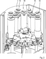
- This known dispenser comprises a turntable supporting a plurality of canisters provided with a stirrer.
- a stirrer driver plate with radially extending fingers is configured to drive the stirrers of all canisters simultaneously.
- Each radial finger of the stirrer driver plate is connected to a drive rod of a stirrer of a respective one of the canisters.
- a stirrer drive is arranged to drive the stirrer driver plate via a crank to make rotations with a diameter corresponding to the distance between the drive axis of the stirrer drive and the bearing connecting the crank to the stirrer driver plate.
- each finger circles around a rotation axis coinciding with the cylinder axis of the associated canister and drives the stirrer of that canister via the drive rod.
- Operational parts such as drives and circuitry for the turntable, the stirrer drive, and actuator for selectively actuating one of the pumps with the associated valve, are positioned in the lower part of the dispenser below the turntable.
- a similar paint dispenser is disclosed in WO 2012/093020 .
- Such paint dispensers are used on Points of Sale, where clients want to mix paints of a selected colour. These Points of Sale also include smaller shops with limited space. Therefore, there is a need for a compact paint dispenser consuming less space.
- a dispenser for liquids selectively composed of mixed components comprising:
- the canisters can be arranged in two or more concentric circular arrays, including an outer circular array and an inner circular array of canisters.
- the stirrer driver plate can comprise radially extending fingers extending between an inner circumference of the stirrer driver plate and an outer circumference of the stirrer driver plate.
- the canisters of the inner circular array have stirrers with a drive crank connected to the outer ends of the fingers and the canisters of the inner circular array have stirrers with a drive crank connected to the stirrer driver plate at the inner circumference, e.g., centrally between two adjacent fingers.
- Each canister may for example comprise a dispense nozzle, e.g., at a bottom side of the container.
- the dispenser comprises at least one pump connected to, or selectively connectable to a canister. More specifically, each canister can be provided with a pump, or the canisters can selectively be connected to a central pump.
- Each pump can be provided with a valve movable between a position allowing withdrawal of liquid from the container by the pump, and a second position closing off the container and allowing dispensing of withdrawn liquid from the pump.
- Each of the valves and pumps can be controlled by a control unit to dispense selected amounts of the respective tinting paste in accordance with a paint formulation of a selected colour.
- canisters of the inner circular array can be provided with a pump-valve assembly of the pump and the valve at the same diameter as canisters of the outer circular array.
- the canisters of the inner circular array can each be provided with a radially extending extension line between canister and the pump-valve assembly.
- the stirrer drive is arranged to drive a gear wheel with a central gear axis rotatably engaging the stirrer driver plate at a wiggle axis at a distance from the gear axis, the distance corresponding to a length of the cranks of the stirrers.
- the gear wheel can for example be part of a top side of a crank wheel, the crank wheel comprising a wheel or cylindrical skirt at its lower side having a central wheel axis coinciding with the wiggle axis.
- the wheel or skirt can rotatably be received in a ring bearing of the stirrer driver plate.
- valve housing 13 contains a stopcock 20 closing off an outlet 18 of the valve housing 13.
- rotatable knob 19 for moving the stopcock 20 between a closing position and a release position.
- the valve body 14 is profiled to define a channel (not shown) between the extension line 12 and the pump housing 16 when the valve body 14 in in a suction position. In this suction position, the piston 17 can be moved outwardly to withdraw liquid from the canister 8A. The valve body 14 can then be rotated and moved downward into a dispensing position, closing off the extension line 12 and aligning the channel with the outlet 18 of the valve housing 13. By rotating the knob 19 into the release position and subsequent inward pushing of the piston 17, liquid is dispensed from the pump housing 16 via the outlet 18 of the valve housing 13.
- the extension lines 12 of the pump-valve assemblies 11A of the inner circular array 9A of canisters 8A have such a length that the pump-valve assemblies 11A are at the same distance to the central axis of the turntable 7 as the pump-valve assemblies 11B of the canisters 8B of the outer circular array 9B. This way, all pump-valve assemblies 11A, 11B are aligned in a single circular array.
- the outlet 10B of the pump-valve assemblies 11B directly connects to the valve housing 13.
- the pump-valve assemblies 11B of the canisters 8B work in the same way as the pump-valve assemblies 11A of the canisters 8A.
- the turntable 7 can be rotated to selectively place each one of the canisters 8A, 8B into a dispense position above the platform 5.
- Figure 4 shows in cross section a canister 8A of the inner circular array 9A in the dispensing position. In this dispensing position, the pump-valve assembly 11A engages a common actuator 21 of the dispenser 1 for engaging and actuating the pump 15, the valve body 14 and the stop cock of the pump-valve assembly 11A.
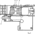
- FIG. 5 shows the common actuator 21 in more detail.
- the common actuator 21 comprises a pump actuator 22 and a stopcock actuator 23.
- the common actuator 21 is static and does not rotate with the turntable 7.
- the pump actuator 22 comprises a gripper 24 which is movable in radial direction by means of a spindle mechanism 25 although other types of drives can also be used if so desired.
- the gripper 24 is a C-shaped gripper.
- the outer end of the piston 17 of the piston pump 15 is provided with a disk 26 sliding into the C-shaped gripper 24 when the respective canister 8A, 8B with the associated pump-valve assembly 11A, 11B is moved into the dispensing position.
- the gripper 24 pulls the piston 17 to suck liquid out of the canister 8A, 8B into the valve housing 16.
- the gripper 24 can push the piston 17 back into the pump housing 16 and force the liquid to flow out of the outlet 18.
- the dispenser 1 further comprises a control unit (not shown) and a user interface, such as a touch screen, in communication with the control unit enabling an operator or user to input a desired paint colour.
- a control unit determines a paint formulation matching the desired paint colour, e.g., by selecting the paint formulation from a database.
- the determined paint formulation typically is a composition of one or more tinting pastes available in the respective canisters 8A, 8B of the dispenser 1, and optionally a base paint.
- the control unit controls rotation of the turntable 7 to sequentially move the canisters 8A, 8B containing the required tinting pastes into the dispense position above a paint can 6 on the platform 5 and controls the common actuator 21 to engage and actuate the pump-valve assembly 11A, 11B of the respective canisters 8A, 8B and dispense the respective tinting pastes one by one in accordance with the paint formulation.
- each canister 8A, 8B is provided with a stirrer 27 extending the full height of the inside of the canister 8A, 8B.
- the stirrers 27 are shown in Figure 4 and comprise a central stirrer shaft 28 and a set of stirrer blades 29 or similar elements attached to the stirrer shaft 21.
- the stirrer driver plate 30 is positioned above the turntable 7 and moveable in a plane parallel to the turntable 7. As shown in Figure 8 , the stirrer driver plate 30 is operatively connected to a stirrer drive 38 by means of a crank wheel 39.
- the stirrer drive 38 is an electric motor.
- the crank wheel 39 comprises a cylindrical skirt or wheel 40 with a wiggle axis W.
- the crank wheel 39 comprises a gear wheel 41 with a gear axis G.
- the distance between the wiggle axis W and the gear axis G corresponds to the length of the drive cranks 34, 35.
- a central flange 42 joins the wheel 40 and the gear wheel 41 to form a single part.
- the gear wheel 41 of the crank wheel 39 is connected to an central axle stump 45 of the turntable 7.
- the gear wheel 41 is driven by the electric motor 38 (see Figure 8 ) via a gear transmission 46 to rotate about the gear axis G jointly with the turntable 7..
- the turntable 7 comprises a circular upper disk 47 and a lower ring 48 of a plate material.
- the upper disk 47 and the lower ring 48 are parallel and coaxial and connected to each other by a circular array of radially extending supports 49 of equal size and shape.
- the lower ring 48 has a teethed inner circumference 50.
- the common actuator 21 (not shown in Figure 8 ) is placed within the lower ring 48, just below the upper disk 47 and at a distance from the path of the radially extending supports 49, and does not rotate with the turntable 7.
- the central axle stump 45 with a channel for guiding the power cable for the electric motor 38.
- the turntable 7 is driven to rotate with the stirrer driver plate 30. Meanwhile, the stirrer driver plate 30 wiggles relative to the rotating turntable 7 to drive the stirrers 27 of all canisters 8A, 8B simultaneously.
Landscapes
- Chemical & Material Sciences (AREA)
- Chemical Kinetics & Catalysis (AREA)
- Reciprocating Pumps (AREA)
- Coating Apparatus (AREA)
Priority Applications (2)
| Application Number | Priority Date | Filing Date | Title |
|---|---|---|---|
| EP23192774.0A EP4512513A1 (fr) | 2023-08-22 | 2023-08-22 | Distributeur pour doser et distribuer sélectivement des liquides |
| PCT/EP2024/073440 WO2025040707A1 (fr) | 2023-08-22 | 2024-08-21 | Distributeur pour doser et distribuer sélectivement des liquides |
Applications Claiming Priority (1)
| Application Number | Priority Date | Filing Date | Title |
|---|---|---|---|
| EP23192774.0A EP4512513A1 (fr) | 2023-08-22 | 2023-08-22 | Distributeur pour doser et distribuer sélectivement des liquides |
Publications (1)
| Publication Number | Publication Date |
|---|---|
| EP4512513A1 true EP4512513A1 (fr) | 2025-02-26 |
Family
ID=87762513
Family Applications (1)
| Application Number | Title | Priority Date | Filing Date |
|---|---|---|---|
| EP23192774.0A Withdrawn EP4512513A1 (fr) | 2023-08-22 | 2023-08-22 | Distributeur pour doser et distribuer sélectivement des liquides |
Country Status (2)
| Country | Link |
|---|---|
| EP (1) | EP4512513A1 (fr) |
| WO (1) | WO2025040707A1 (fr) |
Citations (4)
| Publication number | Priority date | Publication date | Assignee | Title |
|---|---|---|---|---|
| EP0694330A1 (fr) * | 1994-07-21 | 1996-01-31 | FAST S.p.A. | Appareil pour mélanger des produits liquides pour la préparation de matières colorantes pour peintures et similaires |
| EP0800858A1 (fr) | 1996-01-22 | 1997-10-15 | Fluid Management, Inc. | Appareil pour le dosage des peintures |
| WO2000013918A1 (fr) * | 1998-09-02 | 2000-03-16 | Corob Oy | Machine de coloration de peinture de type carrousel |
| WO2012093020A1 (fr) | 2011-01-07 | 2012-07-12 | Fluid Management Operation Llc | Appareil de distribution d'une pluralité de liquides |
-
2023
- 2023-08-22 EP EP23192774.0A patent/EP4512513A1/fr not_active Withdrawn
-
2024
- 2024-08-21 WO PCT/EP2024/073440 patent/WO2025040707A1/fr active Pending
Patent Citations (4)
| Publication number | Priority date | Publication date | Assignee | Title |
|---|---|---|---|---|
| EP0694330A1 (fr) * | 1994-07-21 | 1996-01-31 | FAST S.p.A. | Appareil pour mélanger des produits liquides pour la préparation de matières colorantes pour peintures et similaires |
| EP0800858A1 (fr) | 1996-01-22 | 1997-10-15 | Fluid Management, Inc. | Appareil pour le dosage des peintures |
| WO2000013918A1 (fr) * | 1998-09-02 | 2000-03-16 | Corob Oy | Machine de coloration de peinture de type carrousel |
| WO2012093020A1 (fr) | 2011-01-07 | 2012-07-12 | Fluid Management Operation Llc | Appareil de distribution d'une pluralité de liquides |
Also Published As
| Publication number | Publication date |
|---|---|
| WO2025040707A1 (fr) | 2025-02-27 |
Similar Documents
| Publication | Publication Date | Title |
|---|---|---|
| EP2459877B1 (fr) | Dispositif distributeur de produits fluides ou analogues, et procédé correspondant | |
| US6811058B2 (en) | Valve assembly | |
| EP0642464B1 (fr) | Appareil distributeur ameliore | |
| US8448823B2 (en) | Apparatus for dispensing a plurality of fluids with removable actuator module | |
| US8240513B2 (en) | Fluid dispenser with nested displacement members | |
| WO2011149702A2 (fr) | Systèmes de recirculation à buses rotatives | |
| EP2198950B1 (fr) | Appareil pour distribuer plusieurs fluides | |
| US20210370251A1 (en) | Machine and Method to Automatically Dispense Fluid Products, In Particular Liquid Dyes | |
| EP4512513A1 (fr) | Distributeur pour doser et distribuer sélectivement des liquides | |
| EP2449349B1 (fr) | Distributeur de liquides doté d'éléments de déplacement imbriqués | |
| EP4609946A1 (fr) | Machine de teinture avec pompe volumétrique |
Legal Events
| Date | Code | Title | Description |
|---|---|---|---|
| PUAI | Public reference made under article 153(3) epc to a published international application that has entered the european phase |
Free format text: ORIGINAL CODE: 0009012 |
|
| STAA | Information on the status of an ep patent application or granted ep patent |
Free format text: STATUS: THE APPLICATION HAS BEEN PUBLISHED |
|
| AK | Designated contracting states |
Kind code of ref document: A1 Designated state(s): AL AT BE BG CH CY CZ DE DK EE ES FI FR GB GR HR HU IE IS IT LI LT LU LV MC ME MK MT NL NO PL PT RO RS SE SI SK SM TR |
|
| STAA | Information on the status of an ep patent application or granted ep patent |
Free format text: STATUS: THE APPLICATION IS DEEMED TO BE WITHDRAWN |
|
| 18D | Application deemed to be withdrawn |
Effective date: 20250827 |