EP4512629A1 - Bildaufzeichnungsverfahren - Google Patents
Bildaufzeichnungsverfahren Download PDFInfo
- Publication number
- EP4512629A1 EP4512629A1 EP23791635.8A EP23791635A EP4512629A1 EP 4512629 A1 EP4512629 A1 EP 4512629A1 EP 23791635 A EP23791635 A EP 23791635A EP 4512629 A1 EP4512629 A1 EP 4512629A1
- Authority
- EP
- European Patent Office
- Prior art keywords
- ink
- transport member
- film
- pretreatment liquid
- permeable substrate
- Prior art date
- Legal status (The legal status is an assumption and is not a legal conclusion. Google has not performed a legal analysis and makes no representation as to the accuracy of the status listed.)
- Pending
Links
Images
Classifications
-
- B—PERFORMING OPERATIONS; TRANSPORTING
- B41—PRINTING; LINING MACHINES; TYPEWRITERS; STAMPS
- B41J—TYPEWRITERS; SELECTIVE PRINTING MECHANISMS, i.e. MECHANISMS PRINTING OTHERWISE THAN FROM A FORME; CORRECTION OF TYPOGRAPHICAL ERRORS
- B41J11/00—Devices or arrangements of selective printing mechanisms, e.g. ink-jet printers or thermal printers, for supporting or handling copy material in sheet or web form
- B41J11/0015—Devices or arrangements of selective printing mechanisms, e.g. ink-jet printers or thermal printers, for supporting or handling copy material in sheet or web form for treating before, during or after printing or for uniform coating or laminating the copy material before or after printing
-
- B—PERFORMING OPERATIONS; TRANSPORTING
- B41—PRINTING; LINING MACHINES; TYPEWRITERS; STAMPS
- B41J—TYPEWRITERS; SELECTIVE PRINTING MECHANISMS, i.e. MECHANISMS PRINTING OTHERWISE THAN FROM A FORME; CORRECTION OF TYPOGRAPHICAL ERRORS
- B41J13/00—Devices or arrangements of selective printing mechanisms, e.g. ink-jet printers or thermal printers, specially adapted for supporting or handling copy material in short lengths, e.g. sheets
- B41J13/08—Conveyor bands or like feeding devices
-
- B—PERFORMING OPERATIONS; TRANSPORTING
- B41—PRINTING; LINING MACHINES; TYPEWRITERS; STAMPS
- B41J—TYPEWRITERS; SELECTIVE PRINTING MECHANISMS, i.e. MECHANISMS PRINTING OTHERWISE THAN FROM A FORME; CORRECTION OF TYPOGRAPHICAL ERRORS
- B41J2/00—Typewriters or selective printing mechanisms characterised by the printing or marking process for which they are designed
- B41J2/005—Typewriters or selective printing mechanisms characterised by the printing or marking process for which they are designed characterised by bringing liquid or particles selectively into contact with a printing material
- B41J2/01—Ink jet
- B41J2/21—Ink jet for multi-colour printing
-
- B—PERFORMING OPERATIONS; TRANSPORTING
- B41—PRINTING; LINING MACHINES; TYPEWRITERS; STAMPS
- B41M—PRINTING, DUPLICATING, MARKING, OR COPYING PROCESSES; COLOUR PRINTING
- B41M3/00—Printing processes to produce particular kinds of printed work, e.g. patterns
- B41M3/008—Sequential or multiple printing, e.g. on previously printed background; Mirror printing; Recto-verso printing; using a combination of different printing techniques; Printing of patterns visible in reflection and by transparency; by superposing printed artifacts
-
- B—PERFORMING OPERATIONS; TRANSPORTING
- B41—PRINTING; LINING MACHINES; TYPEWRITERS; STAMPS
- B41M—PRINTING, DUPLICATING, MARKING, OR COPYING PROCESSES; COLOUR PRINTING
- B41M5/00—Duplicating or marking methods; Sheet materials for use therein
-
- B—PERFORMING OPERATIONS; TRANSPORTING
- B41—PRINTING; LINING MACHINES; TYPEWRITERS; STAMPS
- B41M—PRINTING, DUPLICATING, MARKING, OR COPYING PROCESSES; COLOUR PRINTING
- B41M5/00—Duplicating or marking methods; Sheet materials for use therein
- B41M5/0011—Pre-treatment or treatment during printing of the recording material, e.g. heating, irradiating
- B41M5/0017—Application of ink-fixing material, e.g. mordant, precipitating agent, on the substrate prior to printing, e.g. by ink-jet printing, coating or spraying
-
- B—PERFORMING OPERATIONS; TRANSPORTING
- B41—PRINTING; LINING MACHINES; TYPEWRITERS; STAMPS
- B41M—PRINTING, DUPLICATING, MARKING, OR COPYING PROCESSES; COLOUR PRINTING
- B41M5/00—Duplicating or marking methods; Sheet materials for use therein
- B41M5/0041—Digital printing on surfaces other than ordinary paper
- B41M5/0047—Digital printing on surfaces other than ordinary paper by ink-jet printing
-
- B—PERFORMING OPERATIONS; TRANSPORTING
- B41—PRINTING; LINING MACHINES; TYPEWRITERS; STAMPS
- B41M—PRINTING, DUPLICATING, MARKING, OR COPYING PROCESSES; COLOUR PRINTING
- B41M5/00—Duplicating or marking methods; Sheet materials for use therein
- B41M5/0041—Digital printing on surfaces other than ordinary paper
- B41M5/0064—Digital printing on surfaces other than ordinary paper on plastics, horn, rubber, or other organic polymers
-
- B—PERFORMING OPERATIONS; TRANSPORTING
- B41—PRINTING; LINING MACHINES; TYPEWRITERS; STAMPS
- B41M—PRINTING, DUPLICATING, MARKING, OR COPYING PROCESSES; COLOUR PRINTING
- B41M7/00—After-treatment of prints, e.g. heating, irradiating, setting of the ink, protection of the printed stock
- B41M7/009—After-treatment of prints, e.g. heating, irradiating, setting of the ink, protection of the printed stock using thermal means, e.g. infrared radiation, heat
-
- C—CHEMISTRY; METALLURGY
- C09—DYES; PAINTS; POLISHES; NATURAL RESINS; ADHESIVES; COMPOSITIONS NOT OTHERWISE PROVIDED FOR; APPLICATIONS OF MATERIALS NOT OTHERWISE PROVIDED FOR
- C09D—COATING COMPOSITIONS, e.g. PAINTS, VARNISHES OR LACQUERS; FILLING PASTES; CHEMICAL PAINT OR INK REMOVERS; INKS; CORRECTING FLUIDS; WOODSTAINS; PASTES OR SOLIDS FOR COLOURING OR PRINTING; USE OF MATERIALS THEREFOR
- C09D11/00—Inks
- C09D11/30—Inkjet printing inks
- C09D11/32—Inkjet printing inks characterised by colouring agents
- C09D11/322—Pigment inks
-
- C—CHEMISTRY; METALLURGY
- C09—DYES; PAINTS; POLISHES; NATURAL RESINS; ADHESIVES; COMPOSITIONS NOT OTHERWISE PROVIDED FOR; APPLICATIONS OF MATERIALS NOT OTHERWISE PROVIDED FOR
- C09D—COATING COMPOSITIONS, e.g. PAINTS, VARNISHES OR LACQUERS; FILLING PASTES; CHEMICAL PAINT OR INK REMOVERS; INKS; CORRECTING FLUIDS; WOODSTAINS; PASTES OR SOLIDS FOR COLOURING OR PRINTING; USE OF MATERIALS THEREFOR
- C09D11/00—Inks
- C09D11/54—Inks based on two liquids, one liquid being the ink, the other liquid being a reaction solution, a fixer or a treatment solution for the ink
-
- C—CHEMISTRY; METALLURGY
- C09—DYES; PAINTS; POLISHES; NATURAL RESINS; ADHESIVES; COMPOSITIONS NOT OTHERWISE PROVIDED FOR; APPLICATIONS OF MATERIALS NOT OTHERWISE PROVIDED FOR
- C09D—COATING COMPOSITIONS, e.g. PAINTS, VARNISHES OR LACQUERS; FILLING PASTES; CHEMICAL PAINT OR INK REMOVERS; INKS; CORRECTING FLUIDS; WOODSTAINS; PASTES OR SOLIDS FOR COLOURING OR PRINTING; USE OF MATERIALS THEREFOR
- C09D175/00—Coating compositions based on polyureas or polyurethanes; Coating compositions based on derivatives of such polymers
- C09D175/04—Polyurethanes
Definitions
- the present disclosure relates to an image recording method.
- JP2013-49519A discloses, as a printing method for preventing transport stains caused by a transport member and improving ink resistance of the transport member, a printing method of printing, on a recording medium, an ink that a total surface free energy ⁇ calculated from a theoretical expression of Kaelble-Uy is 25 to 30 mN/m and a dispersion component ratio ⁇ dr represented by the following expression 1 is 0.55 to 0.75, and of transporting the recording medium a transport member facing at least a printed surface of the printed recording medium, in which the transport member has a total surface free energy ⁇ calculated from a theoretical expression of Kaelble-Uy of 20 mN/m or less, and has a dispersion component ratio ⁇ dr represented by the following expression 1 of 0.75 to 1.00.
- ⁇ dr ⁇ d / ⁇ (in the expression 1, ⁇ dr is a dispersion component ratio, ⁇ d is a surface free energy of the dispersion component, and ⁇ is a
- the present disclosure has been made in view of such circumstances, and an object of the present disclosure is to provide an image recording method capable of suppressing transfer of an ink film to a transport member in an image recording method including transporting a non-permeable substrate provided with the ink film by applying and drying an ink, in a state in which the transport member and the ink film are in contact with each other.
- the present disclosure includes the following aspects.
- an image recording method capable of suppressing transfer of an ink film to a transport member in an image recording method including transporting a non-permeable substrate provided with the ink film by applying and drying an ink, in a state in which the transport member and the ink film are in contact with each other.
- an upper limit value or a lower limit value described in a certain numerical range may be replaced with an upper limit value or a lower limit value in another numerical range described in a stepwise manner.
- an upper limit value and a lower limit value described in a certain numerical range may be replaced with values shown in Examples.
- the amount of the respective components in the composition means the total amount of the plurality of substances present in the composition unless otherwise specified.
- step includes not only an independent step but also a step whose intended purpose is achieved even in a case in which the step is not clearly distinguished from other steps.
- image means an ink film itself in a case where a pretreatment liquid is not used, and means a laminated film of a pretreatment liquid film and an ink film in a case where the pretreatment liquid is used.
- image recording means formation of the image.
- image in the present disclosure also includes a solid image.
- a description of "applying an ink onto a substrate” includes an aspect of directly applying the ink onto a surface of the substrate, and for example, in a case where a layer A is formed on the substrate, an aspect of directly applying the ink onto a surface of the layer A.
- upstream side means an upstream side of a non-permeable substrate in a transport direction
- downstream side means a downstream side of a non-permeable substrate in the transport direction
- the image recording method (hereinafter, also referred to as "recording method") includes an ink applying step of applying an ink containing water, a pigment, and a resin onto a non-permeable substrate by an inkjet method, an ink drying step of drying the ink applied onto the non-permeable substrate to obtain an ink film, and a step of transporting, by a transport member T, the non-permeable substrate provided with the ink film in a disposition in which the transport member T and the ink film are in contact with each other, in which an absolute value of a difference between a hydrogen bonding component of a surface energy of the ink film and a hydrogen bonding component of a surface energy of the transport member T is 2.0 mN/m or more.
- the recording method according to the present disclosure may include other steps, as necessary.
- an ink film to a transport member in an image recording method including transporting a non-permeable substrate provided with the ink film by applying and drying an ink, in a state in which the transport member and the ink film are in contact with each other.
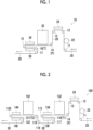
- Fig. 1 is a diagram conceptually showing the first specific example of the image recording apparatus used in the image recording method according to the present disclosure.
- an image recording apparatus 10 which is the image recording apparatus according to the first specific example includes transport rollers 11 to 17 as transport members for transporting a non-permeable substrate 20.
- the image recording apparatus 10 includes, in order from an upstream side in the transport direction along the transport direction of the non-permeable substrate 20, a pretreatment liquid applying device 22 for applying a pretreatment liquid onto the non-permeable substrate 20; a pretreatment liquid drying device 24 for drying the pretreatment liquid applied onto the non-permeable substrate 20; an ink jet head 32 for applying an ink onto the non-permeable substrate 20 by an ink jet method; and ink drying devices 34 and 36 for drying the ink applied onto the non-permeable substrate 20 to obtain an ink film.
- the non-permeable substrate 20 is transported in a direction of an arrow in Fig. 1 by the transport rollers 11 to 17.
- the non-permeable substrate 20 to be transported is subjected to application of the pretreatment liquid by the pretreatment liquid applying device 22, drying of the pretreatment liquid by the pretreatment liquid drying device 24, application of the ink by the ink jet head 32, and drying of the ink by the ink drying devices 34 and 36, in this order.
- the treatment in this order means that the application of the pretreatment liquid, the drying of the pretreatment liquid, the application of the ink, and the drying of the ink are performed in this order with respect to a certain point X on the non-permeable substrate to be transported.
- the pretreatment liquid a pretreatment liquid containing water, a coagulating agent, and a resin is used.
- an ink containing water, a pigment, and a resin is used as the ink.
- Each of the transport rollers 11 to 17 as the transport members for transporting the non-permeable substrate 20 transports the non-permeable substrate 20 while being in contact with an application surface of the pretreatment liquid and the ink (hereinafter, also simply referred to as "application surface”) or a non-application surface of the pretreatment liquid and the ink (hereinafter, also simply referred to as "non-application surface”) in the non-permeable substrate 20.
- application surface an application surface of the pretreatment liquid and the ink
- non-application surface a non-application surface of the pretreatment liquid and the ink
- the non-permeable substrate 20 is transported by the transport roller 11, and then the pretreatment liquid is applied onto the non-permeable substrate 20 by the pretreatment liquid applying device 22.
- the non-permeable substrate 20 to which the pretreatment liquid has been applied is transported by the transport roller 12.
- the pretreatment liquid on the transported non-permeable substrate 20 is dried by the pretreatment liquid drying device 24, and a pretreatment liquid film is obtained on the non-permeable substrate 20.
- the non-permeable substrate 20 provided with the pretreatment liquid film is transported by the transport roller 13 which is in contact with the non-application surface, and then is transported by the transport roller 14 as a transport member P which is in contact with the application surface, in a state in which the transport member P and the pretreatment liquid film are in contact with each other.
- an absolute value of a difference between a hydrogen bonding component of a surface energy of the pretreatment liquid film and a hydrogen bonding component of a surface energy of the transport roller 14 as the transport member P is adjusted to be 2.0 or more (more preferably 10.0 or more and 30.0 or less).
- an absolute value of a difference between a dispersion component of the surface energy of the pretreatment liquid film and a dispersion component of the surface energy of the transport member P is adjusted to be 5.0 or more and 30.0 or less.
- the absolute value of the difference between the hydrogen bonding component of the surface energy of the pretreatment liquid film and the hydrogen bonding component of the surface energy of the transport roller 14 as the transport member P, and the absolute value of the difference between the dispersion component of the surface energy of the pretreatment liquid film and the dispersion component of the surface energy of the transport roller 14 as the transport member P can be adjusted, for example, by adjusting composition of the pretreatment liquid for obtaining the pretreatment liquid film, drying conditions of the pretreatment liquid for obtaining the pretreatment liquid film, a material of the surface (surface in contact with the pretreatment liquid film) of the transport roller 14, and the like.
- the non-permeable substrate 20 provided with the pretreatment liquid film is transported to below the ink jet head 32 by the above-described transport roller 14 (that is, the transport member P).
- the ink jet head 32 By the ink jet head 32, the ink is applied onto the pretreatment liquid film on the non-permeable substrate 20, which has reached below the ink jet head 32.
- the ink applied onto the pretreatment liquid film on the non-permeable substrate 20 is dried by the ink drying devices 34 and 36 to form an ink film.
- the non-permeable substrate 20 provided with the ink film is transported by the transport roller 16 as a transport member T, which is disposed on the downstream side of the ink drying device 36 (that is, the downstream side of the non-permeable substrate 20 in the transport direction), in a disposition in which the transport member T (that is, the transport roller 16) and the ink film are in contact with each other.
- an absolute value of a difference between a dispersion component of the surface energy of the ink film and a dispersion component of the surface energy of the transport member T is adjusted to be 5.0 or more and 30.0 or less.
- a transport member which is located on the most upstream side that is, a transport member closest to the ink film drying device (for example, the transport roller 16 in the image recording apparatus 10) corresponds to the transport member T (that is, the transport member which controls the surface energy with the ink film).
- transport member P a transport member T1 described later
- transport member T2 a transport member closest to the drying device.
- a plurality of ink jet heads may be arranged at the position of the ink jet head 32 along the transport direction.
- a plurality of inks of colors (for example, a first ink and a second ink described later) can be applied in a superimposed manner.
- the plurality of inks of colors applied in a superimposed manner can be dried by the ink drying devices 34 and 36, whereby an ink film derived from the plurality of inks of colors can be obtained.
- the pretreatment liquid applying step and the pretreatment liquid drying step are not essential steps.
- the pretreatment liquid applying device 22 and the pretreatment liquid drying device 24 are not used (that is, the non-permeable substrate 20 is transported to pass through the pretreatment liquid applying device 22 and the pretreatment liquid drying device 24), and the ink may be directly applied onto the non-permeable substrate 20.
- the pretreatment liquid applying device 22, the pretreatment liquid drying device 24, and the transport rollers 11 to 14 may be not included.
- the first specific example may include other elements in addition to the above-described elements.
- Examples of other elements include a unwinding device which is provided on the upstream side of the transport roller 11 and unwinds the non-permeable substrate wound in a roll shape; a winding device which is provided on the downstream side of the transport roller 17 and winds the non-permeable substrate provided with the ink film (that is, the image) is formed; and a tension applying device which applies tension to the non-permeable substrate to be transported.
- examples of other devices also include an ink jet head and an ink drying device, provided on the downstream side of the transport roller 17.
- examples of a case in which the ink jet head and the ink drying device are provided on the downstream side of the transport roller 17 include a second specific example described later.
- the difference in hydrogen bonding component between the ink film and the transport member T (that is, the absolute value of the difference between the hydrogen bonding component of the surface energy of the ink film and the hydrogen bonding component of the surface energy of the transport member T) is 2.0 mN/m or more, as described above.
- the difference in hydrogen bonding component between the ink film and the transport member T is preferably 5.0 mN/m or more, and more preferably 10.0 mN/m or more.
- the upper limit of the difference in hydrogen bonding component between the ink film and the transport member T is not particularly limited, but is, for example, 50.0 mN/m.
- the difference in hydrogen bonding component between the ink film and the transport member T is preferably 40.0 mN/m or less, and more preferably 30.0 mN/m or less.
- Examples of a preferred range of the difference in hydrogen bonding component between the ink film and the transport member T include a range of 10.0 mN/m or more and 30.0 mN/m or less.
- a size relationship between the hydrogen bonding component of the ink film and the hydrogen bonding component of the transport member T (which one is higher) is not particularly limited, but from the viewpoint of manufacturing suitability of the ink, it is preferable that the hydrogen bonding component of the ink film is higher than the hydrogen bonding component of the transport member T.
- the difference in dispersion component between the ink film and the transport member T (that is, the absolute value of the difference between the dispersion component of the surface energy of the ink film and the dispersion component of the surface energy of the transport member T) is preferably 2.0 mN/m or more, and more preferably 5.0 mN/m or more.
- the upper limit of the difference in dispersion component between the ink film and the transport member T is not particularly limited, but is, for example, 50.0 mN/m.
- the difference in hydrogen bonding component between the ink film and the transport member T is preferably 35.0 mN/m or less, and more preferably 30.0 mN/m or less.
- Examples of a preferred range of the difference in dispersion component between the ink film and the transport member T include a range of 5.0 mN/m or more and 30.0 mN/m or less.
- the surface energy (hydrogen bonding component and dispersion component) of the ink film and the surface energy of the transport member T in the present disclosure are calculated by the Owens-Wendt method.
- the surface energy of each of a pretreatment liquid film, a first ink film, a second ink film, a transport member P, a transport member T1, and a transport member T2, which will be described later, is also measured in the same manner.
- the surface energy of the ink film is measured using a non-permeable substrate provided with the ink film under the ink application conditions in the ink applying step and under the drying conditions in the ink drying step (hereinafter, also referred to as "ink film sample").
- a water contact angle and a diiodomethane contact angle described later are measured within 30 minutes after the production of the ink film sample (that is, after the drying of the ink is completed).
- the surface energy of the transport member T is measured using the transport member T itself.
- the contact angle of water and the contact angle of diiodomethane with the surface of the ink film in the ink film sample are measured.
- DM-501 product name, manufactured by Kyowa Interface Science Co., Ltd.
- the surface energy of the ink film is calculated by the Owens-Wendt method using measured values of the contact angles of water and diiodomethane with respect to the surface of the ink film and dispersion components and hydrogen bonding components of water and diiodomethane.
- Equation 1 described below is known as the Young's equation.
- Equation 2 described below is known as the Dupre equation.
- Equation 3 Equation 4, and Equation 5 described below are known as equations using the Owens-Wendt method.
- Equation 1 to Equation 5 the details of each symbol are as follows.
- Equation 6 described below is obtained from Equation 1 to Equation 5 described above.
- ⁇ S d ⁇ L d 1 / 2 + ⁇ S h ⁇ L h 1 / 2 ⁇ L 1 + cos ⁇ / 2
- Equation 6A and Equation 6B are established using water and diiodomethane as the liquid in Equation 6.
- Equation 6A and Equation 6B the details of each symbol are as follows.
- Equation 6A and Equation 6B whereby ⁇ S d and ⁇ S h are calculated.
- the measured values by the above-described measurement method are used.
- the surface energy ⁇ S of the ink film is calculated by substituting the calculated ⁇ S d and ⁇ S h into Expression 3.
- an absolute value of a difference between a surface roughness of the ink film and a surface roughness of the transport member T is preferably 50.0 ⁇ m or less, more preferably 30.0 ⁇ m or less, and still more preferably 10.0 ⁇ m or less.
- the transfer of the ink film to the transport member can be further suppressed.
- the lower limit of the difference in surface roughness between the ink film and the transport member T is not particularly limited.
- the difference in surface roughness between the ink film and the transport member T may be 0 ⁇ m, more than 0 ⁇ m, 0.1 ⁇ m or more, or 1.0 ⁇ m or more.
- the "surface roughness” means an arithmetic average height Ra specified in JIS B 0601-2001.
- the surface roughness of the ink film (including the first ink film and the second ink film described later) is measured using the ink film in the ink film sample described above within 30 minutes after the production of the ink film sample (that is, after the drying of the ink is completed).
- the recording method according to the present disclosure includes an ink applying step of applying an ink containing water, a pigment, and a resin onto a non-permeable substrate by an ink jet method.
- impermeability of the non-permeable substrate denotes a property that a water absorption rate in 24 hours, which is measured in conformity with ASTM D570-98 (2016), is 2.5% or less.
- the unit "%" of the water absorption rate is on a mass basis.
- the above-described water absorption rate is preferably 1.0% or less and more preferably 0.5% or less.
- Examples of a material of the non-permeable substrate include glass, a metal (such as aluminum, zinc, and copper), and a resin (such as polyvinyl chloride, cellulose diacetate, cellulose triacetate, cellulose propionate, cellulose butyrate, cellulose acetate butyrate, cellulose nitrate, polyethylene terephthalate, polyethylene, polystyrene, polypropylene, polycarbonate, polyvinyl acetal, nylon, and an acrylic resin).
- a metal such as aluminum, zinc, and copper
- a resin such as polyvinyl chloride, cellulose diacetate, cellulose triacetate, cellulose propionate, cellulose butyrate, cellulose acetate butyrate, cellulose nitrate, polyethylene terephthalate, polyethylene, polystyrene, polypropylene, polycarbonate, polyvinyl acetal, nylon, and an acrylic resin).
- the material of the non-permeable substrate is a resin. That is, it is preferable that the non-permeable substrate is a resin substrate.
- the material of the non-permeable substrate is preferably polypropylene, polyethylene, polyethylene terephthalate, nylon, an acrylic resin, or polyvinyl chloride.
- the non-permeable substrate As a shape of the non-permeable substrate, a sheet-like (film-like) or a plate-like non-permeable substrate is preferable.
- the non-permeable substrate having such a shape include a glass plate, a metal plate, a resin sheet (resin film), paper on which plastic is laminated, paper on which a metal is laminated or vapor-deposited, and a plastic sheet (plastic film) on which a metal is laminated or vapor-deposited.
- non-permeable substrate made of a resin examples include a resin sheet (resin film), and more specific examples thereof include a flexible packaging material for packaging food or the like, and a panel for guiding the floor of a mass retailer.
- non-permeable substrate examples include a textile (woven fabric) or nonwoven fabric formed of impermeable fibers, in addition to the sheet-like (film-like) or plate-like non-permeable substrate.
- a thickness of the non-permeable substrate is preferably 0.1 ⁇ m to 1,000 ⁇ m, more preferably 0.1 ⁇ m to 800 ⁇ m, and still more preferably 1 ⁇ m to 500 ⁇ m.
- the non-permeable substrate may be subjected to a hydrophilization treatment.
- a hydrophilization treatment include a corona treatment, a plasma treatment, a flame treatment, a heat treatment, an abrasion treatment, a light irradiation treatment (such as an UV treatment), and a flame treatment, but the hydrophilization treatment is not limited thereto.
- the corona treatment can be performed, for example, using CORONA MASTER (product name "PS-10S", manufactured by Shinko Electric & Instrumentation Co., Ltd.). Conditions for the corona treatment may be appropriately selected according to the type and the like of the non-permeable substrate.
- the non-permeable substrate may be a non-permeable substrate having transparency.
- the expression of "having transparency” denotes that a transmittance in visible light having a wavelength of 400 nm to 700 nm is 80% or more (preferably 90% or more).
- the non-permeable substrate is a non-permeable substrate having transparency
- the image is easily visually recognized through the non-permeable substrate from an image non-recorded surface side of the non-permeable substrate.
- a colored image for example, a pattern image such as a character and a figure
- a white image for example, a solid image
- Examples of the ink containing water, a pigment, and a resin include a white ink containing water, a white pigment, and a resin (hereinafter, also simply referred to as "white ink”), and a colored ink containing water, a coloring pigment, and a resin (hereinafter, also simply referred to as "colored ink").
- the coloring pigment means a chromatic pigment (for example, a cyan pigment, a magenta pigment, a yellow pigment, and the like) or a black pigment.
- the colored ink means a chromatic ink (for example, a cyan ink, a magenta ink, a yellow ink, and the like) or a black ink.
- a white ink is preferable.
- the ink applying step only one kind of the ink containing water, a pigment, and a resin may be applied onto the non-permeable substrate, or two or more kinds thereof may be applied onto the non-permeable substrate.
- a first ink containing water, a pigment, and a resin and a second ink containing water, a pigment, and a resin may be applied onto the non-permeable substrate in a superimposed manner in this order by an ink jet method.
- any one of the first ink or the second ink is the white ink and the other is the colored ink; and it is more preferable that the first ink is the colored ink and the second ink is the white ink.
- the first ink and the second ink are applied onto the non-permeable substrate in a superimposed manner
- the first ink and the second ink applied onto the permeable substrate are dried to obtain ink films (specifically, a first ink film derived from the first ink and a second ink film derived from the second ink).
- operation of drying the first ink may be included between the application of the first ink and the application of the second ink, or operation of drying the first ink may not be included.
- the ink (for example, the first ink and the second ink; the same applies hereinafter) contains water.
- a content of the water is preferably 10% by mass or more, more preferably 20% by mass or more, still more preferably 30% by mass or more, and particularly preferably 50% by mass or more with respect to the total amount of the ink.
- the upper limit of the content of the water is appropriately determined according to contents of other components, and is, for example, 99% by mass, preferably 95% by mass, and more preferably 90% by mass with respect to the total amount of the ink.
- the ink contains a pigment.
- the ink is a colored ink
- the ink contains a coloring pigment as the pigment.
- the ink is a white ink
- the ink contains a white pigment as the pigment.
- a commercially available organic pigment or inorganic pigment may be used as the coloring pigment.
- coloring pigment examples include pigments described in " Encyclopedia of Pigments” edited by Seishiro Ito (2000), “Industrial Organic Pigments”, W. Herbst, K. Hunger , JP2002-12607A , JP2002-188025A , JP2003-26978A , and JP2003-342503A .
- the coloring pigment may be a water-insoluble pigment which can be dispersed in water by a dispersing agent, or may be a self-dispersing pigment.
- the self-dispersing pigment is a pigment which can be dispersed in water without using a dispersing agent.
- the self-dispersing pigment is, for example, a compound in which at least one selected from the group consisting of a hydrophilic group such as a carbonyl group, a hydroxyl group, a carboxyl group, a sulfo group, and a phosphoric acid group and salts thereof is chemically bonded to a surface of the pigment directly or through another group.
- a hydrophilic group such as a carbonyl group, a hydroxyl group, a carboxyl group, a sulfo group, and a phosphoric acid group and salts thereof is chemically bonded to a surface of the pigment directly or through another group.
- a content of the coloring pigment is preferably 1% by mass to 20% by mass, more preferably 1% by mass to 15% by mass, and still more preferably 1% by mass to 10% by mass.
- the white pigment is preferably titanium dioxide, barium sulfate, calcium carbonate, or zinc oxide, and more preferably titanium dioxide.
- an average primary particle diameter of the white pigment is preferably 150 nm or more, and more preferably 200 nm or more.
- the average primary particle diameter of the white pigment is preferably 400 nm or less, and more preferably 350 nm or less.
- the average primary particle diameter of the white pigment is a value measured using a transmission electron microscope (TEM).
- TEM transmission electron microscope
- the average primary particle diameter of the white pigment is a value determined by selecting 50 optional particles of the white pigment present in a visual field observed by the TEM, measuring primary particle diameters of the 50 particles, and averaging the measured diameters.
- the transmission electron microscope a transmission electron microscope 1200EX manufactured by JEOL Ltd. can be used.
- a content of the white pigment is preferably 2% by mass to 25% by mass, more preferably 5% by mass to 25% by mass, and still more preferably 10% by mass to 20% by mass.
- the ink contains at least one resin.
- the resin in the ink contributes to film-forming properties of the ink (that is, formability of the ink film).
- a weight-average molecular weight (Mw) of the resin is preferably 1,000 to 300,000, more preferably 2,000 to 200,000, and still more preferably 5,000 to 100,000.
- the weight-average molecular weight means a value measured according to gel permeation chromatography (GPC), unless otherwise specified.
- HLC gel permeation chromatography
- 8020GPC manufactured by Tosoh Corporation
- TSKgel registered trademark
- TEZ-H tetrahydrofuran
- a sample concentration of 0.45% by mass, a flow rate of 0.35 ml/min, a sample injection amount of 10 ⁇ l, and a measurement temperature of 40°C are set, and a RI detector is used.
- the calibration curve is created from eight samples of "Standard sample TSK standard, polystyrene" manufactured by Tosoh Corporation: "F-40", “F-20”, “F-4", "F-1", "A-5000”, “A-2500”, “A-1000”, and "n-propylbenzene”.
- the resin examples include a pigment dispersing resin as a dispersing agent.
- Examples of the resin also include resin particles.
- the ink may contain at least one pigment dispersing resin.
- the pigment dispersing resin is a resin having a function of dispersing a pigment.
- the pigment dispersing resin may be a random copolymer or a block copolymer.
- the pigment dispersing resin may have a crosslinking structure.
- the ink may be prepared using a pigment dispersion liquid containing a pigment and a pigment dispersing resin.
- pigment dispersing resin for example, known polymer dispersing agents, such as polymer dispersing agents described in paragraphs 0029 to 0106 of WO2021/221069A , can be used.
- a ratio of a content of the pigment and a content of the pigment dispersing resin in the ink is preferably 1:0.04 to 1:3, more preferably 1:0.05 to 1:1, and still more preferably 1:0.05 to 1:0.5 on a mass basis.
- the content of the pigment dispersing resin is preferably 0.1% by mass to 10% by mass, more preferably 0.3% by mass to 5% by mass, and still more preferably 0.5% by mass to 2.5% by mass with respect to the total amount of the ink.
- the ink may contain at least one kind of resin particles.
- a resin constituting the resin particles is preferably a water-insoluble resin.
- the "water-insoluble" in the water-insoluble resin means a property that an amount dissolved in 100 g of distilled water at 25°C is less than 2 g.
- a volume average particle diameter of the resin particles is preferably 1 nm to 300 nm, more preferably 3 nm to 200 nm, and still more preferably 5 nm to 150 nm.
- the volume average particle diameter means a value measured using a laser diffraction/scattering type particle size distribution analyzer.
- a particle size distribution measuring device "MICROTRAC MT-3300II" (manufactured by Nikkiso Co., Ltd.) is exemplified.
- the resin particles are at least one selected from the group consisting of acrylic resin particles, ester resin particles, a mixture of acrylic resin particles and ester resin particles, composite particles containing an acrylic resin and an ester resin, styrene-acrylic resin particles, and polyurethane resin particles.
- the acrylic resin means a polymer (homopolymer or copolymer) of a raw monomer including at least one selected from the group consisting of acrylic acid, a derivative of acrylic acid (for example, acrylic acid ester and the like), methacrylic acid, and a derivative of methacrylic acid (for example, methacrylic acid ester and the like).
- a glass transition temperature (Tg) of the resin particles is preferably 50°C to 250°C and more preferably 50°C to 150°C.
- a measurement Tg obtained by actual measurement is employed as the glass transition temperature (Tg) of the resin particles.
- a method of measuring the measurement Tg can refer to paragraph 0111 of JP2015-25076A .
- a content of the resin particles in the ink is preferably 1% by mass to 20% by mass, more preferably 2% by mass to 15% by mass, and still more preferably 2% by mass to 10% by mass with respect to the total amount of the ink.
- the ink contains at least one water-soluble organic solvent.
- water-soluble in the “water-soluble organic solvent” means a property of being dissolved in 1 g or more in 100 g of water at 25°C.
- the type of the water-soluble organic solvent which can be contained in the ink is not particularly limited, and examples thereof include monoalcohol having 1 to 4 carbon atoms; diol such as 1,3-propanediol, 1,3-butanediol, 1,4-butanediol, 2-butene-1,4-diol, 2-ethyl-1,3-hexanediol, 2-methyl-2,4-pentanediol, 1,2-octanediol, 1,2-hexanediol, 1,2-pentanediol, and 4-methyl-1,2-pentanediol; triol such as glycerin, 1,2,6-hexanetriol, and trimethylolpropane; alkylene glycol such as ethylene glycol and propylene glycol; alkylene glycol monoalkyl ether such as ethylene glycol monoalkyl ether and propylene glycol monoalkyl ether
- the water-soluble organic solvent in the ink includes at least one selected from the group consisting of alkylene glycol and alkylene glycol monoalkyl ether.
- a content of the water-soluble organic solvent is preferably 10% by mass to 40% by mass and more preferably 15% by mass to 30% by mass with respect to the total amount of the ink.
- the ink may contain an additive such as a surfactant, a water-soluble resin, a co-sensitizer, an ultraviolet absorbing agent, an antioxidant, a fading inhibitor, a conductive salt, and a basic compound, as necessary.
- an additive such as a surfactant, a water-soluble resin, a co-sensitizer, an ultraviolet absorbing agent, an antioxidant, a fading inhibitor, a conductive salt, and a basic compound, as necessary.
- a pH (25°C) of the ink is preferably 7 to 10 and more preferably 7.5 to 9.5.
- the pH of the ink can be measured by the same method as that for the pH of the pretreatment liquid.
- a viscosity (25°C) of the ink is preferably 0.5 mPa ⁇ s to 30 mPa ⁇ s, more preferably 2 mPa ⁇ s to 20 mPa ⁇ s, preferably 2 mPa ⁇ s to 15 mPa ⁇ s, and even more preferably 3 mPa ⁇ s to 10 mPa ⁇ s.
- the viscosity of the ink is measured at 25°C using a viscometer, for example, a TV-22 type viscometer manufactured by Toki Sangyo Co., Ltd.
- a surface tension (25°C) of the ink is preferably 60 mN/m or less, more preferably 20 mN/m to 50 mN/m, and still more preferably 25 mN/m to 40 mN/m.
- the surface tension is measured at 25°C using a surface tension meter, for example, by a plate method using an automatic surface tension meter (trade name, "CBVP-Z”) manufactured by Kyowa Interface Science Co., Ltd.
- CBVP-Z automatic surface tension meter
- the application of the ink is performed by an ink jet method.
- the ejection method of the ink by the ink jet method is not particularly limited, and for example, any known methods such as an electric charge control method of jetting the ink using electrostatic attraction force, a drop-on-demand method (pressure pulse method) using vibration pressure of a piezoelectric element, an acoustic ink jet method of converting an electric signal into an acoustic beam, irradiating the ink with the acoustic beam, and jetting the ink by using radiation pressure, a thermal ink jet method (BUBBLE JET (registered trademark)) of heating the ink, forming bubbles, and using generated pressure, and the like may be used.
- any known methods such as an electric charge control method of jetting the ink using electrostatic attraction force, a drop-on-demand method (pressure pulse method) using vibration pressure of a piezoelectric element, an acoustic ink jet method of converting an electric signal into an acoustic beam, irradiating the ink with the acou
- JP1979-59936A JP-S54-59936A
- JP-S54-59936A an ink jet recording method of causing an ink to experience a rapid volume change by the action of thermal energy and jetting the ink from a nozzle by using the acting force resulting from the change of state.
- a method described in paragraphs 0093 to 0105 of JP2003-306623A can also be applied.
- the application of the ink onto the non-permeable substrate by the ink jet recording method can be performed by allowing the ink to be jetted from a nozzle of an ink jet head.
- the way of using the ink jet head also includes a shuttle method of performing recording while a short serial head is allowed to scan in the width direction of the recorded medium, and a line method of using a line head in which recording elements are arranged correspondingly to the entire range of one side of the recorded medium.
- image recording can be performed on the entire surface of the recorded medium by scanning the recorded medium in a direction intersecting the direction in which the recording elements are aligned.
- a transport system such as a carriage that allows the short head to perform scanning in the shuttle method is unnecessary.
- a carriage is not required to move, and a complicated scanning control with the recorded medium is unnecessary, and only the recorded medium moves. Therefore, according to the line method, an increase in the recording speed of an image is achieved as compared with the shuttle method.
- the ink is preferably applied using an ink jet head having a resolution of 300 dpi or more (more preferably 600 dpi or more and still more preferably 800 dpi or more).
- dpi is an abbreviation for dot per inch, and 1 inch is 2.54 cm.
- a droplet amount of the ink is preferably 1 picoliter (pL) to 10 pL and more preferably 1.5 pL to 6 pL.
- the recording method according to the present disclosure includes an ink drying step of drying the ink applied onto the non-permeable substrate to obtain an ink film.
- a method for drying the ink is not particularly limited, and examples thereof include infrared (IR) drying, hot air drying (for example, a dryer and the like), and heating and drying with a heating device (for example, a heater, a hot plate, a heating furnace, and the like).
- IR infrared
- hot air drying for example, a dryer and the like
- heating and drying with a heating device for example, a heater, a hot plate, a heating furnace, and the like.
- the method of heating and drying may be a method of combining two or more of the above-described methods.
- the heating drying can be performed by heating the ink from at least one of an image-recorded surface side or an image non-recorded surface side of the non-permeable substrate.
- a heating temperature in the heating and drying of the ink is preferably 35°C or higher, more preferably 40°C or higher, still more preferably 50°C or higher, and even more preferably 60°C or higher.
- the upper limit value of the heating temperature is not particularly limited, but is preferably 100°C and more preferably 90°C.
- a heating time in the heating and drying of the ink is not particularly limited, but is preferably 1 second to 180 seconds, more preferably 1 second to 120 seconds, and still more preferably 1 second to 60 seconds.
- the recording method according to the present disclosure includes a step of transporting, by a transport member T, the non-permeable substrate provided with the ink film in a disposition in which the transport member T and the ink film are in contact with each other.
- Examples of the transport member T include a transport roller.
- a plurality of transport members which are in contact with the ink film may be present.
- the transport member T in this case is a transport member located on the most upstream side among the plurality of transport members which are in contact with the ink film.
- a material of the transport member T is not particularly limited as long as it is a material in which the difference in hydrogen bonding component between the ink film and the transport member T is 2.0 or more.
- the recording method may include, before the ink applying step, a pretreatment liquid applying step of applying a pretreatment liquid containing water, a coagulating agent, and a resin onto the non-permeable substrate, a pretreatment liquid drying step of drying the pretreatment liquid applied onto the non-permeable substrate to obtain a pretreatment liquid film, and a step of transporting, by a transport member P, the non-permeable substrate provided with the pretreatment liquid film in a disposition in which the transport member P and the pretreatment liquid film are in contact with each other.
- an absolute value of a difference between a dispersion component of a surface energy of the pretreatment liquid film and a dispersion component of a surface energy of the transport member P is preferably 2.0 mN/m or more, and preferably 5.0 mN/m or more.
- the streaks in the image are defects caused by the transfer of the pretreatment liquid film to the transport member P. Specifically, the defects occur in the pretreatment liquid film due to the transfer of the pretreatment liquid film to the transport member P, and then the ink is applied onto the defects, whereby the streaks occur in the image.
- the upper limit of the difference in dispersion component between the pretreatment liquid film and the transport member P is not particularly limited, and may be, for example, 30.0 mN/m, 25.0 mN/m, or 21.0 mN/m.
- Examples of a preferred range of the difference in dispersion component between the pretreatment liquid film and the transport member P include a range of 2.0 mN/m or more and 30.0 mN/m or less.
- a difference in hydrogen bonding component between the pretreatment liquid film and the transport member P (that is, an absolute value of a difference between a hydrogen bonding component of the surface energy of the pretreatment liquid film and a hydrogen bonding component of the surface energy of the transport member P) is, for example, 20.0 mN/m or more and 50.0 mN/m, preferably 30.0 mN/m or more and 45.0 mN/m or less.
- a size relationship between the hydrogen bonding component of the pretreatment liquid film and the hydrogen bonding component of the transport member P (which one is higher) is not particularly limited, but from the viewpoint of manufacturing suitability of the pretreatment liquid, it is preferable that the hydrogen bonding component of the pretreatment liquid film is higher than the hydrogen bonding component of the transport member P.
- the pretreatment liquid contains water, a coagulating agent, and a resin.
- the pretreatment liquid contains water.
- a content of water is preferably 50% by mass or more and more preferably 60% by mass or more with respect to the total amount of the pretreatment liquid.
- the upper limit of the content of water depends on the amount of other components, but is preferably 90% by mass or less and more preferably 80% by mass or less with respect to the total amount of the pretreatment liquid.
- the pretreatment liquid contains at least one coagulating agent.
- the coagulating agent in the pretreatment liquid coagulates the components in the ink on the non-permeable substrate. As a result, image quality of the image can be improved.
- the coagulating agent is at least one selected from the group consisting of an organic acid, a polyvalent metal compound, a metal complex, and a cationic polymer.
- Preferred examples of the coagulating agent also include coagulating agents described in paragraphs 0122 to 0130 of WO2020/195360A .
- Examples of the organic acid include an organic compound having an acidic group.
- Examples of the acidic group include a phosphoric acid group, a phosphonic acid group, a phosphinic acid group, a sulfuric acid group, a sulfonic acid group, a sulfinic acid group, and a carboxy group.
- a phosphoric acid group or a carboxy group is preferable, and a carboxy group is more preferable.
- At least a part of the acidic group is dissociated in the pretreatment liquid.
- organic acid examples include, as an organic compound having a carboxy group, (meth)acrylic acid, poly(meth)acrylic acid, acetic acid, formic acid, benzoic acid, glycolic acid, malonic acid, malic acid (preferably DL-malic acid), maleic acid, succinic acid, glutaric acid, pimelic acid, adipic acid, fumaric acid, citric acid, tartaric acid, phthalic acid, 4-methylphthalic acid, lactic acid, pyrrolidone carboxylic acid, pyrone carboxylic acid, pyrrole carboxylic acid, furan carboxylic acid, pyridine carboxylic acid, coumaric acid, thiophene carboxylic acid, and nicotinic acid.
- di- or higher valent carboxylic acid (hereinafter, also referred to as polyvalent carboxylic acid) is preferable, and dicarboxylic acid is more preferable.
- malonic acid malic acid, maleic acid, succinic acid, glutaric acid, pimelic acid, adipic acid, fumaric acid, tartaric acid, 4-methylphthalic acid, or citric acid is preferable; and malonic acid, malic acid, tartaric acid, succinic acid, glutaric acid, pimelic acid, adipic acid, or citric acid is more preferable.
- the organic acid has a low pKa (for example, 1.0 to 5.0).
- pKa for example, 1.0 to 5.0.
- surface charge of particles, for example, the pigment stably dispersed in the ink by a weakly acidic functional group such as a carboxy group, resin particles, and the like can be reduced by bringing the ink into contact with the organic acid having a lower pKa to degrade dispersion stability.
- the organic acid has a low pKa, high solubility in water, and a valence of divalent or more.
- the organic acid has a high buffer capacity in a pH region with a pKa lower than a pKa of the functional group (for example, a carboxy group) which stably disperses particles in the ink.
- Examples of the polyvalent metal compound include a polyvalent metal salt.
- polyvalent metal salt examples include an organic acid polyvalent metal salt and an inorganic acid polyvalent metal salt.
- organic acid polyvalent metal salt a polyvalent metal salt of the above-described organic acid (for example, formic acid, acetic acid, or benzoic acid) is preferable.
- the inorganic acid polyvalent metal salt a nitric acid polyvalent metal salt, a hydrochloric acid polyvalent metal salt, or a thiocyanic acid polyvalent metal salt is preferable.
- polyvalent metal salt examples include salts of alkaline earth metals of Group 2 (such as magnesium and calcium) in the periodic table, salts of transition metals of Group 3 (such as lanthanum) in the periodic table, salts of metals of Group 13 (such as aluminum) in the periodic table, and salts of lanthanides (such as neodymium).
- a calcium salt, a magnesium salt, or an aluminum salt is preferable, and a calcium salt or a magnesium salt is more preferable.
- an organic acid polyvalent metal salt is preferable, and an organic acid calcium salt or an organic acid magnesium salt is more preferable.
- the polyvalent metal compound is dissociated into polyvalent metal ions and counter-ions in the pretreatment liquid.
- a metal complex containing, as a ligand, at least one selected from the group consisting of acetate, acetylacetonate, methylacetoacetate, ethylacetoacetate, octylene glycolate, butoxyacetylacetonate, lactate, a lactate ammonium salt, and triethanol aminate is preferable.
- the metal complex may be a commercially available product.
- Various organic ligands, particularly various multidentate ligands which are capable of forming metal chelate catalysts are commercially available. Therefore, the metal complex may be a metal complex prepared by combining a commercially available organic ligand with a metal.
- the cationic polymer is a homopolymer of a cationic monomer having a primary to tertiary amino group or a quaternary ammonium base, or a copolymer or a condensed polymer of a cationic monomer and a non-cationic monomer.
- the cationic polymer may be used in any form of a water-soluble polymer or a water-insoluble polymer (that is, latex particles).
- Examples of the cationic polymer include polyvinylpyridine salt, polyalkylaminoethyl acrylate, polyalkylaminoethyl methacrylate, polyvinylimidazole, polyethyleneimine, polybiguanide, polyguanide, polyallylamine, and derivatives thereof.
- the weight-average molecular weight of the cationic polymer is small.
- the weight-average molecular weight thereof is preferably 1,000 to 500,000, more preferably 1,500 to 200,000, and still more preferably 2,000 to 100,000. It is advantageous that the weight-average molecular weight thereof is 1,000 or more from the viewpoint of coagulating rate. It is advantageous that the weight-average molecular weight thereof is 500,000 or less from the viewpoint of jetting reliability.
- the weight-average molecular weight thereof is not limited thereto in a case where the pretreatment liquid is applied onto a resin substrate by a method other than the ink jet recording method.
- a content of the coagulating agent in the pretreatment liquid is preferably 0.1% by mass to 40% by mass, more preferably 0.1% by mass to 30% by mass, still more preferably 1% by mass to 20% by mass, and even more preferably 1% by mass to 10% by mass with respect to the total amount of the pretreatment liquid.
- the pretreatment liquid contains at least one resin.
- the resin in the pretreatment liquid contributes to film-forming properties of the pretreatment liquid (that is, formability of the pretreatment liquid film).
- the same resin as the resin in the ink for example, the resin particles
- the same resin as the resin in the ink for example, the resin particles
- a content of the resin in the pretreatment liquid is not particularly limited.
- the content of the resin is preferably 0.5% by mass to 30% by mass, more preferably 1% by mass to 20% by mass, and particularly preferably 1% by mass to 15% by mass with respect to the total amount of the pretreatment liquid.
- the pretreatment liquid may contain at least one water-soluble organic solvent.
- the same water-soluble organic solvent as the water-soluble organic solvent which can be contained in the ink can be used.
- the ink may contain an additive such as a surfactant, a water-soluble resin, a cosensitizer, an ultraviolet absorbing agent, an antioxidant, a fading inhibitor, a conductive salt, and a basic compound, as necessary.
- an additive such as a surfactant, a water-soluble resin, a cosensitizer, an ultraviolet absorbing agent, an antioxidant, a fading inhibitor, a conductive salt, and a basic compound, as necessary.
- a pH of the pretreatment liquid is preferably 2.0 to 7.0 and more preferably 2.0 to 4.0.
- the pH of the pretreatment liquid is measured by the same method as in the pH of the ink.
- a viscosity of the pretreatment liquid is preferably 0.5 mPa ⁇ s to 10 mPa ⁇ s and more preferably 1 mPa ⁇ s to 5 mPa ⁇ s.
- the viscosity is a value measured at 25°C using a viscometer.
- the viscosity of the pretreatment liquid is measured by the same method as in the viscosity of the ink.
- a surface tension of the pretreatment liquid is preferably 60 mN/m or less, more preferably 20 mN/m to 50 mN/m, and still more preferably 30 mN/m to 45 mN/m.
- the surface tension is a value measured at a temperature of 25°C.
- the surface tension of the pretreatment liquid is measured by the same method as in the surface tension of the ink.
- a method of applying the pretreatment liquid is not particularly limited, and examples thereof include known methods such as a coating method, a dipping method, and an ink jet recording method.
- Examples of the coating method include known coating methods using a bar coater, an extrusion die coater, an air doctor coater, a blade coater, a rod coater, a knife coater, a squeeze coater, a reverse roll coater, or the like.
- the recording method according to the aspect including the pretreatment liquid applying step includes a pretreatment liquid drying step of drying the pretreatment liquid applied onto the non-permeable substrate to obtain a pretreatment liquid film.
- a method of drying the pretreatment liquid is not particularly limited, but for example, the same method as the method exemplified in the method of drying the ink can be applied.
- the recording method according to the aspect including the pretreatment liquid applying step may include a step of transporting, by a transport member P, the non-permeable substrate provided with the pretreatment liquid film in a disposition in which the transport member P and the pretreatment liquid film are in contact with each other.
- Examples of the transport member P include a transport roller.
- a plurality of transport members which are in contact with the pretreatment liquid film may be present.
- the transport member P in this case is a transport member located on the most upstream side among the plurality of transport members which are in contact with the pretreatment liquid film.
- a material of the transport member P is not particularly limited as long as it is a material in which the difference in dispersion component between the pretreatment liquid film and the transport member P is 2.0 or more.
- a recording method X one embodiment of the recording method according to the present disclosure (hereinafter, referred to as a recording method X) will be described, but the recording method according to the present disclosure is not limited to the recording method X.
- the recording method X includes a first ink applying step of applying a first ink containing water, a pigment, and a resin onto a non-permeable substrate by an ink jet method, a first ink drying step of drying the first ink applied onto the non-permeable substrate to obtain a first ink film, a first transporting step of transporting, by a transport member T1, the non-permeable substrate provided with the first ink film in a disposition in which the transport member T1 and the first ink film are in contact with each other, a second ink applying step of applying a second ink containing water, a pigment, and a resin onto the first ink film on the non-permeable substrate which has been transported by the transport member T1, by an ink jet method, a second ink drying step of drying the second ink applied onto the first ink film on the non-permeable substrate to obtain a second ink film, and a second transporting step of transporting, by a transport member T2, the non-permeable substrate provided
- the recording method X may include other steps, as necessary.
- the transfer of the first ink film to the transport member T1 can be suppressed, and the transfer of the second ink film to the transport member T2 can be suppressed.
- any one of the first ink or the second ink is a white ink containing water, a white pigment, and a resin, and the other is a colored ink containing water, a coloring pigment, and a resin; and it is more preferable that the first ink is the colored ink and the second ink is the white ink.
- the second specific example is an example of an image recording apparatus used in the above-described recording method X.
- Fig. 2 is a diagram conceptually showing the second specific example of the image recording apparatus used in the image recording method according to the present disclosure (specifically, the recording method X).
- an image recording apparatus 100 which is the image recording apparatus according to the second specific example includes transport rollers 11 to 14 and 115 to 122 as transport members for transporting a non-permeable substrate 20.
- the image recording apparatus 100 includes, in order from an upstream side in the transport direction along the transport direction of the non-permeable substrate 20, a pretreatment liquid applying device 22 for applying a pretreatment liquid onto the non-permeable substrate 20; a pretreatment liquid drying device 24 for drying the pretreatment liquid applied onto the non-permeable substrate 20; a first ink jet head 132 for applying the first ink onto the non-permeable substrate 20 by an ink jet method; first ink drying devices 134 and 136 for drying the first ink applied onto the non-permeable substrate 20 to obtain the first ink film; a second ink jet head 142 for applying the second ink onto the first ink film on the non-permeable substrate 20 by an ink jet method; and second ink drying devices 144 and 146 for drying the second ink applied onto the first ink film on the non-permeable substrate 20 to obtain the second ink film.
- the non-permeable substrate 20 is transported in a direction of an arrow in Fig. 2 by the transport rollers 11 to 14 and 115 to 122.
- the non-permeable substrate 20 to be transported is subjected to application of the pretreatment liquid by the pretreatment liquid applying device 22, drying of the pretreatment liquid by the pretreatment liquid drying device 24, application of the first ink by the first ink jet head 132, drying of the ink by the first ink drying devices 134 and 136, application of the second ink by the second ink jet head 142, and drying of the second ink by the second ink drying devices 144 and 146, in this order.
- the pretreatment liquid a pretreatment liquid containing water, a coagulating agent, and a resin is used.
- Preferred aspects of the pretreatment liquid are as described above.
- first ink and the second ink inks containing water, a pigment, and a resin are used.
- a preferred combination of the first ink and the second ink is a combination in which the first ink is any one of a white ink containing water, a white pigment, and a resin or a colored ink containing water, a coloring pigment (note: including a black pigment), and a resin (note: including a black ink), and the second ink is the other of the white ink or the colored ink.
- a more preferred combination of the first ink and the second ink is a combination in which the first ink is the above-described colored ink and the second ink is the above-described white ink.
- Each of the transport rollers 111 to 122 as the transport members for transporting the non-permeable substrate 20 transports the non-permeable substrate 20 while being in contact with the application surface and the non-application surface in the non-permeable substrate 20.
- the pretreatment liquid is applied onto the non-permeable substrate 20 to be transported, and then the pretreatment liquid is dried to obtain a pretreatment liquid film.
- the flow until the pretreatment liquid film is obtained is the same as the flow until the pretreatment liquid film is obtained in the image recording apparatus 10 according to the first specific example.
- the non-permeable substrate 20 provided with the pretreatment liquid film is transported to below the first ink jet head 132 by the transport roller 14 (that is, the transport member P) in a disposition in which the transport roller 14 (that is, the transport member P) and the pretreatment film are in contact with each other.
- the first ink jet head 132 By the first ink jet head 132, the first ink is applied onto the pretreatment liquid film on the non-permeable substrate 20, which has reached below the first ink jet head 132.
- the first ink applied onto the pretreatment liquid film on the non-permeable substrate 20 is dried by the first ink drying devices 134 and 136 to form the first ink film.
- the non-permeable substrate 20 provided with the first ink film is transported by the transport roller 116 as a transport member T1, which is disposed on the downstream side of the first ink drying device 136 in a disposition in which the transport member T1 (that is, the transport roller 116) and the first ink film are in contact with each other.
- the non-permeable substrate 20 transported by the transport member T1 (that is, the transport roller 116) is further transported by the transport roller 117, the transport roller 118, and the transport roller 119, and reaches below the second ink jet head 142.
- the second ink jet head 142 By the second ink jet head 142, the second ink is applied onto the first ink film on the non-permeable substrate 20, which has reached below the second ink jet head 142.
- the second ink applied onto the first ink film on the non-permeable substrate 20 is dried by the second ink drying devices 144 and 146 to form the second ink film.
- the non-permeable substrate 20 provided with the second ink film is transported by the transport roller 121 as a transport member T2, which is disposed on the downstream side of the second ink drying device 146 (that is, the downstream side of the non-permeable substrate 20 in the transport direction), in a disposition in which the transport member T2 (that is, the transport roller 121) and the second ink film are in contact with each other.
- the absolute value of the difference between the hydrogen bonding component of the surface energy of the first ink film and the hydrogen bonding component of the surface energy of the transport roller 116 as the transport member T1 is adjusted to be 2.0 or more (preferably 10.0 or more and 30.0 or less).
- an absolute value of a difference between a dispersion component of the surface energy of the first ink film and a dispersion component of the surface energy of the transport member T1 is adjusted to be 5.0 or more and 30.0 or less.
- the absolute value of the difference between the hydrogen bonding component of the surface energy of the first ink film and the hydrogen bonding component of the surface energy of the transport roller 116 as the transport member T1, and the absolute value of the difference between the dispersion component of the surface energy of the first ink film and the dispersion component of the surface energy of the transport roller 116 as the transport member T1 can be adjusted, for example, by adjusting composition of the first ink for obtaining the first ink film, drying conditions of the first ink for obtaining the first ink film, a material of the surface (surface in contact with the first ink film) of the transport roller 116, and the like.
- the absolute value of the difference between the hydrogen bonding component of the surface energy of the second ink film and the hydrogen bonding component of the surface energy of the transport roller 121 as the transport member T2 is adjusted to be 2.0 or more (preferably 10.0 or more and 30.0 or less).
- an absolute value of a difference between a dispersion component of the surface energy of the second ink film and a dispersion component of the surface energy of the transport member T2 is adjusted to be 5.0 or more and 30.0 or less.
- the absolute value of the difference between the hydrogen bonding component of the surface energy of the second ink film and the hydrogen bonding component of the surface energy of the transport roller 121 as the transport member T2, and the absolute value of the difference between the dispersion component of the surface energy of the second ink film and the dispersion component of the surface energy of the transport roller 121 as the transport member T2 can be adjusted, for example, by adjusting composition of the second ink for obtaining the second ink film, drying conditions of the second ink for obtaining the second ink film, a material of the surface (surface in contact with the second ink film) of the transport roller 121, and the like.
- a plurality of first ink jet heads may be arranged at the position of the first ink jet head 132 along the transport direction.
- a plurality of first inks of colors can be applied in a superimposed manner.
- the plurality of first inks of colors applied in a superimposed manner can be dried by the first ink drying devices 134 and 136, whereby the first ink film derived from the plurality of first inks of colors can be obtained.
- a plurality of second ink jet heads may be arranged at the position of the second ink jet head 142 along the transport direction.
- a plurality of second inks of colors can be applied in a superimposed manner.
- the plurality of second inks of colors applied in a superimposed manner can be dried by the second ink drying devices 144 and 146, whereby the second ink film derived from the plurality of second inks of colors can be obtained.
- the pretreatment liquid applying step and the pretreatment liquid drying step are not essential steps.
- the pretreatment liquid applying step and the pretreatment liquid drying step may be omitted, and the first ink may be directly applied onto the non-permeable substrate 20.
- the pretreatment liquid applying device 22, the pretreatment liquid drying device 24, and the transport rollers 11 to 14 may be not included.
- the second specific example may include other elements in addition to the above-described elements.
- the difference in hydrogen bonding component between the first ink film and the transport member T1 (that is, the absolute value of the difference between the hydrogen bonding component of the surface energy of the first ink film and the hydrogen bonding component of the surface energy of the transport member T1) is 2.0 mN/m or more, as described above.
- the difference in hydrogen bonding component between the ink film and the transport member T is preferably 5.0 mN/m or more, and more preferably 10.0 mN/m or more.
- the upper limit of the difference in hydrogen bonding component between the first ink film and the transport member T1 is not particularly limited, but is, for example, 50.0 mN/m.
- the difference in hydrogen bonding component between the first ink film and the transport member T1 is preferably 40.0 mN/m or less, and more preferably 30.0 mN/m or less.
- Examples of a preferred range of the difference in hydrogen bonding component between the first ink film and the transport member T1 include a range of 10.0 mN/m or more and 30.0 mN/m or less.
- a size relationship between the hydrogen bonding component of the first ink film and the hydrogen bonding component of the transport member T1 (which one is higher) is not particularly limited, but from the viewpoint of manufacturing suitability of the ink, it is preferable that the hydrogen bonding component of the first ink film is higher than the hydrogen bonding component of the transport member T1.
- a preferred range of the difference in hydrogen bonding component between the second ink film and the transport member T2 is the same as the preferred range of the difference in hydrogen bonding component between the first ink film and the transport member T1.
- Examples of a combination of the difference in hydrogen bonding component between the first ink film and the transport member T1 and the difference in hydrogen bonding component between the second ink film and the transport member T2 include a combination in which the difference in hydrogen bonding component between the first ink film and the transport member T1 is 10.0 mN/m or more and 30.0 mN/m or less and the difference in hydrogen bonding component between the second ink film and the transport member T2 is 10.0 mN/m or more and 30.0 mN/m or less.
- the difference in dispersion component between the first ink film and the transport member T1 (that is, the absolute value of the difference between the dispersion component of the surface energy of the first ink film and the dispersion component of the surface energy of the transport member T1) is preferably 2.0 mN/m or more, and more preferably 5.0 mN/m or more.
- the upper limit of the difference in dispersion component between the first ink film and the transport member T1 is not particularly limited, but is, for example, 50.0 mN/m.
- the difference in hydrogen bonding component between the first ink film and the transport member T1 is preferably 35.0 mN/m or less, and more preferably 30.0 mN/m or less.
- Examples of a preferred range of the difference in dispersion component between the first ink film and the transport member T1 include a range of 5.0 mN/m or more and 30.0 mN/m or less.
- a preferred range of the difference in dispersion component between the second ink film and the transport member T2 is the same as the preferred range of the difference in dispersion component between the first ink film and the transport member T1.
- Examples of a combination of the difference in dispersion component between the first ink film and the transport member T1 and the difference in between the second ink film and the transport member T2 include a combination in which the difference in between the first ink film and the transport member T1 is 5.0 mN/m or more and 30.0 mN/m or less and the difference in dispersion component between the second ink film and the transport member T2 is 5.0 mN/m or more and 30.0 mN/m or less.
- a difference in surface roughness between the first ink film and the transport member T1 (that is, an absolute value of a difference between a surface roughness of the first ink film and a surface roughness of the transport member T1) is preferably 50.0 ⁇ m or less, more preferably 30.0 ⁇ m or less, and still more preferably 10.0 ⁇ m or less.
- the transfer of the first ink film to the transport member T1 can be further suppressed.
- the lower limit of the difference in surface roughness between the first ink film and the transport member T1 is not particularly limited.
- the difference in surface roughness between the first ink film and the transport member T1 may be 0 ⁇ m, more than 0 ⁇ m, 0.1 ⁇ m or more, or 1.0 ⁇ m or more.
- a preferred range of the difference in surface roughness between the second ink film and the transport member T2 is the same as the preferred range of the difference in surface roughness between the first ink film and the transport member T1.
- Examples of a combination of the difference in surface roughness between the first ink film and the transport member T1 and the difference in surface roughness between the second ink film and the transport member T2 include a combination in which the difference in surface roughness between the first ink film and the transport member T1 is 10.0 ⁇ m or less and the difference in surface roughness between the second ink film and the transport member T2 is 10.0 ⁇ m or less.
- the recording method may include, before the first ink applying step, a pretreatment liquid applying step of applying a pretreatment liquid containing water, a coagulating agent, and a resin onto the non-permeable substrate, a pretreatment liquid drying step of drying the pretreatment liquid applied onto the non-permeable substrate to obtain a pretreatment liquid film, and a step of transporting, by a transport member P, the non-permeable substrate provided with the pretreatment liquid film in a disposition in which the transport member P and the pretreatment liquid film are in contact with each other.
- a difference in dispersion component between the pretreatment liquid film and the transport member P is 5.0 mN/m or more.
- the pretreatment liquid applying step, the pretreatment liquid drying step, and the step of transporting in a disposition in which the transport member P and the pretreatment liquid film are in contact with each other are as described above.
- Pretreatment liquid No. PC1 PC2 PC3 Coagulating agent Glutaric acid 4.1 4.1 Succinic acid 0.5 0.5 Calcium acetate 6.0 Resin particles SUPERFLEX E-4800 8.0 8.0 SUPERFLEX 500M 8.0 Additive BYK-024 0.01 0.01 0.01 Dimethylaminoethanol 0.1 0.1 OLFINE E1010 0.2 0.2 0.2 0.2 Water Residual amount Residual amount Residual amount Residual amount Residual amount Residual amount
- the content shown in Table 1 indicates the content (% by mass) of the solid content in the aqueous dispersion liquid with respect to the total amount of the pretreatment liquid.
- residual amount means a residual amount which is to be 100% by mass in total.
- the inks W1 to W4 are white inks, the inks K1 and K2 are black inks, the ink M1 is a magenta ink, and the ink C1 is a cyan ink.
- the content shown in Table 2 indicates the content (% by mass) of the solid content in the aqueous dispersion liquid with respect to the total amount of the ink.
- residual amount means a residual amount which is to be 100% by mass in total.
- Inks W1 to W4 were prepared using the following white pigment dispersion liquid 1.
- the solution 1 was added dropwise to the above-described three-neck flask over 4 hours, and the solution 2 was added dropwise thereto over 5 hours.
- the obtained reaction solution was heated to 70°C, 12.0 g of dimethylethanolamine was added thereto, propylene glycol was added thereto, and the resulting solution was stirred, thereby obtaining a 30% by mass solution of the pigment dispersing resin 1.
- the above-described mass ratio was a value not including dimethylaminoethanol.
- An acid value of the pigment dispersing resin 1 was 200 mgKOH/g.
- a pigment dispersion liquid 1 was prepared using a Lady Mill model LSG-4U-08 (manufactured by Aimex Co., Ltd.).
- a titanium dioxide pigment (average primary particle diameter: 210 nm, trade name "PF-690", manufactured by Ishihara Sangyo Kasha, Ltd.) as a white pigment
- 15 parts by mass of a 30% by mass solution of the pigment dispersing resin 1 15 parts by mass of a 30% by mass solution of the pigment dispersing resin 1
- 40 parts by mass of ultrapure water were charged into a zirconia container.
- 40 parts by mass of 0.5 mm ⁇ zirconia beads (Torayceram beads manufactured by Toray Industries, Inc.) were added thereto, and the mixture was mixed gently using a spatula.
- the zirconia container containing the obtained mixture was put into the Lady mill, and dispersed at a rotation speed of 1,000 rpm (revolutions per minute) for 5 hours. After the dispersion was completed, the beads were removed by filtration with a gauze, thereby obtaining a white pigment dispersion liquid 1 in which a concentration of the white pigment was 45% by mass.
- an image recording apparatus having a structure in which two ink jet heads are arranged at the position of the ink jet head 32 along the transport direction was prepared.
- a transport roller R1 shown in Table 3 was used as the transport rollers 11 to 17 in the image recording apparatus 10.
- a wire bar coater was used as the pretreatment liquid applying device 22 as the pretreatment liquid applying device 22.
- the pretreatment liquid drying device 24 As the pretreatment liquid drying device 24, a dryer was used.
- piezo full-line heads with a width of 1200 dpi/30 inch width were used.
- the ink K1 As an ink to be applied from the first ink jet head (hereinafter, referred to as a first ink), the ink K1 was used, as an ink to be applied from the second ink jet head (hereinafter, referred to as the second ink), the ink W1 was used, and as a pretreatment liquid, the pretreatment liquid PC1 was used.
- non-permeable substrate A a polyethylene terephthalate (PET) substrate ("FE2001” manufactured by Futamura Chemical Co., Ltd.; thickness: 12 ⁇ m, width: 780 mm, length: 4,000 m; hereinafter, referred to as "non-permeable substrate A”) was used.
- PET polyethylene terephthalate
- Image recording was performed in a state in which the non-permeable substrate 20 (that is, the non-permeable substrate A) was continuously transported at a transportation speed of 50 m/min by the transport members (that is, the transport rollers 11 to 17) in the image recording apparatus 10, the pretreatment liquid was applied onto the continuously transported non-permeable substrate A, the pretreatment liquid was dried, the first ink was applied, the second ink was applied, and the ink was dried (that is, the first ink and the second ink were dried) in this order.
- the transport members that is, the transport rollers 11 to 17
- the pretreatment liquid PC1 was applied onto the non-permeable substrate A to be transported by the pretreatment liquid applying device 22 such that the application amount was approximately 1.7 g/m 2 , and the applied pretreatment liquid PC1 was dried by the pretreatment liquid drying device 24 at 50°C for 2 seconds to obtain a pretreatment liquid film.
- the non-permeable substrate A provided with the pretreatment liquid film was transported to below the ink jet head 32 while bringing the transport roller 14 as the transport member P into contact with the pretreatment liquid film.
- the ink K1 as the first ink was applied from the first ink jet head in a form of a solid image onto the pretreatment liquid film on the non-permeable substrate A transported to below the ink jet head 32, and the ink W1 as the second ink was applied from the second ink jet head in a form of a solid image onto the applied first ink.
- the non-permeable substrate A provided with the ink film was transported by the transport roller 17 while bringing the transport roller 16 as the transport member T into contact with the ink film.
- a surface energy (hydrogen bonding component and dispersion component) of the transport roller 14 as the transport member P was measured by the above-described method.
- the obtained result was defined as the surface energy (hydrogen bonding component and dispersion component) common to the transport member P and the transport member T.
- a surface roughness (arithmetic average height Ra specified in JIS B 0601-2001) of the transport roller 14 as the transport member P was measured using a laser microscope (Color 3D laser microscope VK-9710 manufactured by Keyence Corporation).
- the obtained result was defined as the surface roughness ( ⁇ m) common to the transport member P and the transport member T.
- a contact angle of water and a contact angle of diiodomethane on the surface of the pretreatment liquid film in the sample were measured.
- a contact angle measuring device a product name "DM-501" manufactured by Kyowa Interface Science Co., Ltd. was used. From these contact angles, the surface energy (hydrogen bonding component and dispersion component) of the pretreatment liquid film was obtained by the above-described method.
- a contact angle of water and a contact angle of diiodomethane on the surface of the pretreatment liquid film in the ink film sample were measured.
- a contact angle measuring device a product name "DM-501" manufactured by Kyowa Interface Science Co., Ltd. was used. From these contact angles, the surface energy (hydrogen bonding component and dispersion component) of the ink film was obtained by the above-described method.
- a surface roughness (arithmetic average height Ra specified in JIS B 0601-2001) of the surface of the ink film in the above-described ink film sample was measured using a laser microscope (Color 3D laser microscope VK-9710 manufactured by Keyence Corporation).
- the obtained result was defined as the surface roughness ( ⁇ m) of the ink film.
- the recording of the solid image described above was performed for 100 m in terms of the length of the non-permeable substrate A.
- the rank in which the transferring of the ink film to the transport member was most suppressed is 5.
- the recording of the solid image described above was performed for 100 m in terms of the length of the non-permeable substrate A. That is, the length of the recorded solid image (that is, the dimension of the solid image in the length direction of the non-permeable substrate A) was 100 m. A width of the solid image (that is, a dimension of the solid image in the width direction of the non-permeable substrate A) was set to 70 cm.
- the streaks in the image are defects caused by the transferring of the pretreatment liquid film to the transport member P (that is, the transport roller 14).
- the rank in which the streaks in the image (that is, the transferring of the pretreatment liquid film to the transport member P) were most suppressed is 5.
- a production of the ink film sample was carried out on the non-permeable substrate having a length of 100 m. That is, the length of the formed ink film (that is, the dimension of the ink film in the length direction of the non-permeable substrate A) was 100 m. A width of the ink film (that is, a dimension of the ink film in the width direction of the non-permeable substrate A) was set to 70 cm.
- Example 4 The same operations as in Example 1 were carried out, except that the combination of all transport members in the image recording apparatus 10, the type of the pretreatment liquid, and the type of the ink were changed as shown in Table 4.
- the unit of the surface roughness and the difference in surface roughness is ⁇ m
- the unit of the dispersion component of the surface energy, the hydrogen bonding component of the surface energy, the difference in dispersion component, and the difference in hydrogen bonding component is mN/m.
- Comparative Example 1 in which the difference in hydrogen bonding component between the ink film and the transport member T was less than 2.0 mN/m, the transferring of the ink film to the transport roller was remarkable.
- a transport roller R1 shown in Table 3 was used as the transport rollers 11 to 14 and 115 to 122 in the image recording apparatus 100.
- a wire bar coater was used as the pretreatment liquid applying device 22 as the pretreatment liquid applying device 22.
- the pretreatment liquid drying device 24 As the pretreatment liquid drying device 24, a dryer was used.
- piezo full-line heads with a width of 1200 dpi/30 inch width were used.
- the pretreatment liquid PC1 As a treatment liquid, the pretreatment liquid PC1 was used, as a first ink, the ink K1 was used, and as a second ink, the ink W1 was used.
- the same PET substrate (non-permeable substrate A) as in Example 1 was used as the non-permeable substrate 20 as the non-permeable substrate 20 as the non-permeable substrate 20.
- Image recording was performed in a state in which the non-permeable substrate 20 (that is, the non-permeable substrate A) was continuously transported at a transportation speed of 50 m/min by the transport members (that is, the transport rollers 11 to 14 and 115 to 122) in the image recording apparatus 100, the pretreatment liquid was applied onto the continuously transported non-permeable substrate A, the pretreatment liquid was dried, the first ink was applied, the first ink was dried, the second ink was applied, and the second ink was dried in this order.
- the transport members that is, the transport rollers 11 to 14 and 115 to 122
- the pretreatment liquid PC1 was applied onto the non-permeable substrate A to be transported by the pretreatment liquid applying device 22 such that the application amount was approximately 1.7 g/m 2 , and the applied pretreatment liquid PC1 was dried by the pretreatment liquid drying device 24 at 50°C for 2 seconds to obtain a pretreatment liquid film.
- the non-permeable substrate A provided with the pretreatment liquid film was transported to below the first ink jet head 132 while bringing the transport roller 14 as the transport member P into contact with the pretreatment liquid film.
- the ink K1 as the first ink was applied from the ink jet head 132 onto the pretreatment liquid film on the non-permeable substrate A transported to below the first ink jet head 132 in a form of a solid image.
- the ink K1 as the first ink applied onto the pretreatment liquid film on the non-permeable substrate A was dried with hot air at 80°C for a total of 30 seconds by the first ink drying devices 134 and 136 to obtain a first ink film.
- the non-permeable substrate A provided with the first ink film was transported while bringing the transport roller 116 as the transport member T1 into contact with the first ink film, and then transported to below the second ink jet head 142 by the transport rollers 117 to 119.
- the ink W1 as the second ink was applied from the second ink jet head 142 onto the first ink film on the non-permeable substrate A transported to below the second ink jet head 142 in a form of a solid image.
- Application conditions of the second ink were the same as the application conditions of the first ink.
- the ink W1 as the second ink applied onto the first ink film on the non-permeable substrate A was dried with hot air at 80°C for a total of 30 seconds by the second ink drying devices 144 and 146 to obtain a second ink film.
- the non-permeable substrate A provided with the second ink film was transported by the transport roller 122 while bringing the transport roller 121 as the transport member T2 into contact with the second ink film.
- Example 1 The measurements regarding the ink of Example 1 were performed for each of the first ink and the second ink.
- a relationship between the first ink and the transport member T1 (difference in hydrogen bonding component, difference in dispersion component, and difference in surface roughness) and a relationship between the second ink and the transport member T2 (difference in hydrogen bonding component, difference in dispersion component, and difference in surface roughness) were obtained by the same methods as the relationship between the ink and the transport member T (difference in hydrogen bonding component, difference in dispersion component, and difference in surface roughness) in Example 1.
- the transferring of the first ink film and the transferring of the second ink film were evaluated in the same manner as in the transferring of the ink film in Example 1.
- the scratches of the first ink film and the scratches of the second ink film were evaluated in the same manner as in the scratches of the ink film in Example 1.
- an image recorded material in which the solid image (that is, the pretreatment liquid film, the first ink film, and the second ink) was provided on the non-permeable substrate A was used for evaluation.
- JP2022-069381 filed on April 20, 2022 is incorporated in the present specification by reference.
Landscapes
- Chemical & Material Sciences (AREA)
- Organic Chemistry (AREA)
- Life Sciences & Earth Sciences (AREA)
- Engineering & Computer Science (AREA)
- Materials Engineering (AREA)
- Wood Science & Technology (AREA)
- Physics & Mathematics (AREA)
- Health & Medical Sciences (AREA)
- General Health & Medical Sciences (AREA)
- Thermal Sciences (AREA)
- Toxicology (AREA)
- Chemical Kinetics & Catalysis (AREA)
- Ink Jet (AREA)
- Ink Jet Recording Methods And Recording Media Thereof (AREA)
Applications Claiming Priority (2)
| Application Number | Priority Date | Filing Date | Title |
|---|---|---|---|
| JP2022069381 | 2022-04-20 | ||
| PCT/JP2023/013018 WO2023203983A1 (ja) | 2022-04-20 | 2023-03-29 | 画像記録方法 |
Publications (2)
| Publication Number | Publication Date |
|---|---|
| EP4512629A1 true EP4512629A1 (de) | 2025-02-26 |
| EP4512629A4 EP4512629A4 (de) | 2025-10-15 |
Family
ID=88419720
Family Applications (1)
| Application Number | Title | Priority Date | Filing Date |
|---|---|---|---|
| EP23791635.8A Pending EP4512629A4 (de) | 2022-04-20 | 2023-03-29 | Bildaufzeichnungsverfahren |
Country Status (5)
| Country | Link |
|---|---|
| US (1) | US20250033396A1 (de) |
| EP (1) | EP4512629A4 (de) |
| JP (1) | JPWO2023203983A1 (de) |
| CN (1) | CN119053451A (de) |
| WO (1) | WO2023203983A1 (de) |
Family Cites Families (24)
| Publication number | Priority date | Publication date | Assignee | Title |
|---|---|---|---|---|
| JPS5459936A (en) | 1977-10-03 | 1979-05-15 | Canon Inc | Recording method and device therefor |
| JP2003026978A (ja) | 1998-09-08 | 2003-01-29 | Ricoh Co Ltd | 記録液体 |
| JP4441995B2 (ja) | 2000-06-28 | 2010-03-31 | 三菱化学株式会社 | 光重合性組成物、光重合性着色組成物およびカラーフィルター |
| JP4061876B2 (ja) | 2000-10-10 | 2008-03-19 | 東洋インキ製造株式会社 | 活性エネルギー線硬化型インクジェットインキ |
| JP4171607B2 (ja) | 2002-04-16 | 2008-10-22 | 富士フイルム株式会社 | 水性インク |
| JP2003342503A (ja) | 2002-05-28 | 2003-12-03 | Konica Minolta Holdings Inc | インクジェット記録用ブラックインクおよび画像形成方法 |
| JP2004275863A (ja) * | 2003-03-14 | 2004-10-07 | Konica Minolta Holdings Inc | 塗布方法及び定着部材 |
| JP2005053663A (ja) * | 2003-08-06 | 2005-03-03 | Ricoh Co Ltd | 画像形成装置、記録液、搬送ベルト及び記録液カートリッジ |
| JP2007210692A (ja) * | 2006-02-07 | 2007-08-23 | Fuji Xerox Co Ltd | 液滴吐出装置 |
| JP5809485B2 (ja) * | 2011-08-31 | 2015-11-11 | 理想科学工業株式会社 | 印刷方法及び搬送部材 |
| JP5705695B2 (ja) * | 2011-09-29 | 2015-04-22 | 富士フイルム株式会社 | インクジェット記録物 |
| JP2013119445A (ja) * | 2011-12-06 | 2013-06-17 | Fujifilm Corp | インクジェット記録装置及びニップローラ |
| JP2014168946A (ja) * | 2013-02-05 | 2014-09-18 | Seiko Epson Corp | インクジェット記録方法、インクジェット記録装置、および記録物 |
| JP5993815B2 (ja) | 2013-07-26 | 2016-09-14 | 富士フイルム株式会社 | インクジェット用インク組成物、インクセット、及び画像形成方法 |
| JP2015100927A (ja) * | 2013-11-21 | 2015-06-04 | 株式会社リコー | 画像形成方法及び画像形成装置 |
| JP6645201B2 (ja) * | 2015-06-10 | 2020-02-14 | 株式会社リコー | インク、並びにインクジェット記録方法、インクジェット記録装置、及び記録物 |
| JP2020044752A (ja) * | 2018-09-20 | 2020-03-26 | キヤノン株式会社 | インクジェット記録方法、及びインクジェット記録装置 |
| JP7179964B2 (ja) | 2019-03-28 | 2022-11-29 | 富士フイルム株式会社 | 非浸透性基材用インクジェットインク、画像記録方法、及びラミネート体の製造方法 |
| WO2021186844A1 (ja) * | 2020-03-19 | 2021-09-23 | 富士フイルム株式会社 | 画像形成装置 |
| CN115315491B (zh) | 2020-03-27 | 2023-06-09 | 富士胶片株式会社 | 喷墨记录用油墨及图像记录方法 |
| JP7399011B2 (ja) * | 2020-03-27 | 2023-12-15 | 富士フイルム株式会社 | 画像形成システム |
| EP4144532B1 (de) | 2020-04-27 | 2025-12-24 | FUJIFILM Corporation | Bildaufzeichnungsverfahren |
| JP7491056B2 (ja) * | 2020-05-26 | 2024-05-28 | 株式会社リコー | 乾燥装置、印刷装置、及び印刷方法 |
| JP7647369B2 (ja) | 2020-10-23 | 2025-03-18 | 株式会社デンソー | 燃料電池システム |
-
2023
- 2023-03-29 JP JP2024516156A patent/JPWO2023203983A1/ja active Pending
- 2023-03-29 EP EP23791635.8A patent/EP4512629A4/de active Pending
- 2023-03-29 WO PCT/JP2023/013018 patent/WO2023203983A1/ja not_active Ceased
- 2023-03-29 CN CN202380034935.9A patent/CN119053451A/zh active Pending
-
2024
- 2024-10-17 US US18/918,448 patent/US20250033396A1/en active Pending
Also Published As
| Publication number | Publication date |
|---|---|
| EP4512629A4 (de) | 2025-10-15 |
| CN119053451A (zh) | 2024-11-29 |
| WO2023203983A1 (ja) | 2023-10-26 |
| JPWO2023203983A1 (de) | 2023-10-26 |
| US20250033396A1 (en) | 2025-01-30 |
Similar Documents
| Publication | Publication Date | Title |
|---|---|---|
| EP3760682B1 (de) | Tintensatz, bildaufzeichnungsverfahren, verfahren zur herstellung von laminat, material mit aufgezeichnetem bild, und laminat | |
| EP3689631B1 (de) | Verfahren zur erzeugung eines bildes und tintenset | |
| EP3950146A1 (de) | Tintenstrahltinte für undurchlässiges substrat, verfahren zur bildaufzeichnung und verfahren zur herstellung eines laminats | |
| EP3848421B1 (de) | Tintenzusammensetzung zum drucken auf einer undurchlässigen basis und bildaufzeichnungsverfahren | |
| EP4052906B1 (de) | Bildaufzeichnungsprodukt und herstellungsverfahren dafür | |
| US20250222711A1 (en) | Image recording method and image recording apparatus | |
| US20250001787A1 (en) | Ink jet recording method | |
| US12480017B2 (en) | Pretreatment liquid for ink jet ink, ink set, image recording method, method of producing laminate, image recorded material, and laminate | |
| EP4512629A1 (de) | Bildaufzeichnungsverfahren | |
| EP3750639B1 (de) | Verfahren zur herstellung eines aufgezeichneten mediums und bildaufzeichnungsverfahren | |
| EP4624183A1 (de) | Bildaufzeichnungsverfahren | |
| EP4563365A1 (de) | Bildaufzeichnungsverfahren und bildaufzeichnungsvorrichtung | |
| EP4663413A1 (de) | Bildaufzeichnungsverfahren | |
| EP4588685A1 (de) | Tintenstrahlaufzeichnungsverfahren | |
| EP4684976A1 (de) | Bildaufzeichnungsverfahren | |
| EP4501656A1 (de) | Tintenstrahlaufzeichnungsverfahren | |
| EP4624540A1 (de) | Verfahren zur herstellung einer pigmentdispersion, verfahren zur herstellung einer tintenstrahltinte und bildaufzeichnungsverfahren | |
| EP4667231A1 (de) | Vorbehandlungsflüssigkeit für tintenstrahltinte, tintensatz, bildaufzeichnungsverfahren, laminatherstellungsverfahren, bildaufzeichnungsmaterial und laminat | |
| EP4410565A1 (de) | Tintenstrahlaufzeichnungsverfahren und verfahren zur herstellung eines laminats |
Legal Events
| Date | Code | Title | Description |
|---|---|---|---|
| STAA | Information on the status of an ep patent application or granted ep patent |
Free format text: STATUS: THE INTERNATIONAL PUBLICATION HAS BEEN MADE |
|
| PUAI | Public reference made under article 153(3) epc to a published international application that has entered the european phase |
Free format text: ORIGINAL CODE: 0009012 |
|
| STAA | Information on the status of an ep patent application or granted ep patent |
Free format text: STATUS: REQUEST FOR EXAMINATION WAS MADE |
|
| 17P | Request for examination filed |
Effective date: 20241018 |
|
| AK | Designated contracting states |
Kind code of ref document: A1 Designated state(s): AL AT BE BG CH CY CZ DE DK EE ES FI FR GB GR HR HU IE IS IT LI LT LU LV MC ME MK MT NL NO PL PT RO RS SE SI SK SM TR |
|
| DAV | Request for validation of the european patent (deleted) | ||
| DAX | Request for extension of the european patent (deleted) | ||
| A4 | Supplementary search report drawn up and despatched |
Effective date: 20250911 |
|
| RIC1 | Information provided on ipc code assigned before grant |
Ipc: B41M 5/00 20060101AFI20250905BHEP Ipc: B41J 2/01 20060101ALI20250905BHEP Ipc: B41J 2/21 20060101ALI20250905BHEP Ipc: C09D 11/322 20140101ALI20250905BHEP |