EP4512680A1 - Procédé de commande d'un véhicule automobile autonome au moins partiellement autonome - Google Patents
Procédé de commande d'un véhicule automobile autonome au moins partiellement autonome Download PDFInfo
- Publication number
- EP4512680A1 EP4512680A1 EP24190889.6A EP24190889A EP4512680A1 EP 4512680 A1 EP4512680 A1 EP 4512680A1 EP 24190889 A EP24190889 A EP 24190889A EP 4512680 A1 EP4512680 A1 EP 4512680A1
- Authority
- EP
- European Patent Office
- Prior art keywords
- motor vehicle
- ego
- road user
- determined
- relevant road
- Prior art date
- Legal status (The legal status is an assumption and is not a legal conclusion. Google has not performed a legal analysis and makes no representation as to the accuracy of the status listed.)
- Pending
Links
Images


Classifications
-
- B—PERFORMING OPERATIONS; TRANSPORTING
- B60—VEHICLES IN GENERAL
- B60W—CONJOINT CONTROL OF VEHICLE SUB-UNITS OF DIFFERENT TYPE OR DIFFERENT FUNCTION; CONTROL SYSTEMS SPECIALLY ADAPTED FOR HYBRID VEHICLES; ROAD VEHICLE DRIVE CONTROL SYSTEMS FOR PURPOSES NOT RELATED TO THE CONTROL OF A PARTICULAR SUB-UNIT
- B60W30/00—Purposes of road vehicle drive control systems not related to the control of a particular sub-unit, e.g. of systems using conjoint control of vehicle sub-units
- B60W30/14—Adaptive cruise control
- B60W30/16—Control of distance between vehicles, e.g. keeping a distance to preceding vehicle
-
- B—PERFORMING OPERATIONS; TRANSPORTING
- B60—VEHICLES IN GENERAL
- B60W—CONJOINT CONTROL OF VEHICLE SUB-UNITS OF DIFFERENT TYPE OR DIFFERENT FUNCTION; CONTROL SYSTEMS SPECIALLY ADAPTED FOR HYBRID VEHICLES; ROAD VEHICLE DRIVE CONTROL SYSTEMS FOR PURPOSES NOT RELATED TO THE CONTROL OF A PARTICULAR SUB-UNIT
- B60W30/00—Purposes of road vehicle drive control systems not related to the control of a particular sub-unit, e.g. of systems using conjoint control of vehicle sub-units
- B60W30/14—Adaptive cruise control
- B60W30/143—Speed control
-
- B—PERFORMING OPERATIONS; TRANSPORTING
- B60—VEHICLES IN GENERAL
- B60W—CONJOINT CONTROL OF VEHICLE SUB-UNITS OF DIFFERENT TYPE OR DIFFERENT FUNCTION; CONTROL SYSTEMS SPECIALLY ADAPTED FOR HYBRID VEHICLES; ROAD VEHICLE DRIVE CONTROL SYSTEMS FOR PURPOSES NOT RELATED TO THE CONTROL OF A PARTICULAR SUB-UNIT
- B60W30/00—Purposes of road vehicle drive control systems not related to the control of a particular sub-unit, e.g. of systems using conjoint control of vehicle sub-units
- B60W30/14—Adaptive cruise control
- B60W30/16—Control of distance between vehicles, e.g. keeping a distance to preceding vehicle
- B60W30/165—Automatically following the path of a preceding lead vehicle, e.g. "electronic tow-bar"
-
- B—PERFORMING OPERATIONS; TRANSPORTING
- B60—VEHICLES IN GENERAL
- B60W—CONJOINT CONTROL OF VEHICLE SUB-UNITS OF DIFFERENT TYPE OR DIFFERENT FUNCTION; CONTROL SYSTEMS SPECIALLY ADAPTED FOR HYBRID VEHICLES; ROAD VEHICLE DRIVE CONTROL SYSTEMS FOR PURPOSES NOT RELATED TO THE CONTROL OF A PARTICULAR SUB-UNIT
- B60W10/00—Conjoint control of vehicle sub-units of different type or different function
- B60W10/04—Conjoint control of vehicle sub-units of different type or different function including control of propulsion units
-
- B—PERFORMING OPERATIONS; TRANSPORTING
- B60—VEHICLES IN GENERAL
- B60W—CONJOINT CONTROL OF VEHICLE SUB-UNITS OF DIFFERENT TYPE OR DIFFERENT FUNCTION; CONTROL SYSTEMS SPECIALLY ADAPTED FOR HYBRID VEHICLES; ROAD VEHICLE DRIVE CONTROL SYSTEMS FOR PURPOSES NOT RELATED TO THE CONTROL OF A PARTICULAR SUB-UNIT
- B60W10/00—Conjoint control of vehicle sub-units of different type or different function
- B60W10/18—Conjoint control of vehicle sub-units of different type or different function including control of braking systems
-
- B—PERFORMING OPERATIONS; TRANSPORTING
- B60—VEHICLES IN GENERAL
- B60W—CONJOINT CONTROL OF VEHICLE SUB-UNITS OF DIFFERENT TYPE OR DIFFERENT FUNCTION; CONTROL SYSTEMS SPECIALLY ADAPTED FOR HYBRID VEHICLES; ROAD VEHICLE DRIVE CONTROL SYSTEMS FOR PURPOSES NOT RELATED TO THE CONTROL OF A PARTICULAR SUB-UNIT
- B60W10/00—Conjoint control of vehicle sub-units of different type or different function
- B60W10/20—Conjoint control of vehicle sub-units of different type or different function including control of steering systems
-
- B—PERFORMING OPERATIONS; TRANSPORTING
- B60—VEHICLES IN GENERAL
- B60W—CONJOINT CONTROL OF VEHICLE SUB-UNITS OF DIFFERENT TYPE OR DIFFERENT FUNCTION; CONTROL SYSTEMS SPECIALLY ADAPTED FOR HYBRID VEHICLES; ROAD VEHICLE DRIVE CONTROL SYSTEMS FOR PURPOSES NOT RELATED TO THE CONTROL OF A PARTICULAR SUB-UNIT
- B60W30/00—Purposes of road vehicle drive control systems not related to the control of a particular sub-unit, e.g. of systems using conjoint control of vehicle sub-units
- B60W30/08—Active safety systems predicting or avoiding probable or impending collision or attempting to minimise its consequences
- B60W30/09—Taking automatic action to avoid collision, e.g. braking and steering
-
- B—PERFORMING OPERATIONS; TRANSPORTING
- B60—VEHICLES IN GENERAL
- B60W—CONJOINT CONTROL OF VEHICLE SUB-UNITS OF DIFFERENT TYPE OR DIFFERENT FUNCTION; CONTROL SYSTEMS SPECIALLY ADAPTED FOR HYBRID VEHICLES; ROAD VEHICLE DRIVE CONTROL SYSTEMS FOR PURPOSES NOT RELATED TO THE CONTROL OF A PARTICULAR SUB-UNIT
- B60W30/00—Purposes of road vehicle drive control systems not related to the control of a particular sub-unit, e.g. of systems using conjoint control of vehicle sub-units
- B60W30/08—Active safety systems predicting or avoiding probable or impending collision or attempting to minimise its consequences
- B60W30/095—Predicting travel path or likelihood of collision
- B60W30/0953—Predicting travel path or likelihood of collision the prediction being responsive to vehicle dynamic parameters
-
- B—PERFORMING OPERATIONS; TRANSPORTING
- B60—VEHICLES IN GENERAL
- B60W—CONJOINT CONTROL OF VEHICLE SUB-UNITS OF DIFFERENT TYPE OR DIFFERENT FUNCTION; CONTROL SYSTEMS SPECIALLY ADAPTED FOR HYBRID VEHICLES; ROAD VEHICLE DRIVE CONTROL SYSTEMS FOR PURPOSES NOT RELATED TO THE CONTROL OF A PARTICULAR SUB-UNIT
- B60W30/00—Purposes of road vehicle drive control systems not related to the control of a particular sub-unit, e.g. of systems using conjoint control of vehicle sub-units
- B60W30/08—Active safety systems predicting or avoiding probable or impending collision or attempting to minimise its consequences
- B60W30/095—Predicting travel path or likelihood of collision
- B60W30/0956—Predicting travel path or likelihood of collision the prediction being responsive to traffic or environmental parameters
-
- B—PERFORMING OPERATIONS; TRANSPORTING
- B60—VEHICLES IN GENERAL
- B60W—CONJOINT CONTROL OF VEHICLE SUB-UNITS OF DIFFERENT TYPE OR DIFFERENT FUNCTION; CONTROL SYSTEMS SPECIALLY ADAPTED FOR HYBRID VEHICLES; ROAD VEHICLE DRIVE CONTROL SYSTEMS FOR PURPOSES NOT RELATED TO THE CONTROL OF A PARTICULAR SUB-UNIT
- B60W30/00—Purposes of road vehicle drive control systems not related to the control of a particular sub-unit, e.g. of systems using conjoint control of vehicle sub-units
- B60W30/14—Adaptive cruise control
- B60W30/16—Control of distance between vehicles, e.g. keeping a distance to preceding vehicle
- B60W30/17—Control of distance between vehicles, e.g. keeping a distance to preceding vehicle with provision for special action when the preceding vehicle comes to a halt, e.g. stop and go
-
- B—PERFORMING OPERATIONS; TRANSPORTING
- B60—VEHICLES IN GENERAL
- B60W—CONJOINT CONTROL OF VEHICLE SUB-UNITS OF DIFFERENT TYPE OR DIFFERENT FUNCTION; CONTROL SYSTEMS SPECIALLY ADAPTED FOR HYBRID VEHICLES; ROAD VEHICLE DRIVE CONTROL SYSTEMS FOR PURPOSES NOT RELATED TO THE CONTROL OF A PARTICULAR SUB-UNIT
- B60W30/00—Purposes of road vehicle drive control systems not related to the control of a particular sub-unit, e.g. of systems using conjoint control of vehicle sub-units
- B60W30/18—Propelling the vehicle
- B60W30/18009—Propelling the vehicle related to particular drive situations
- B60W30/18154—Approaching an intersection
-
- B—PERFORMING OPERATIONS; TRANSPORTING
- B60—VEHICLES IN GENERAL
- B60W—CONJOINT CONTROL OF VEHICLE SUB-UNITS OF DIFFERENT TYPE OR DIFFERENT FUNCTION; CONTROL SYSTEMS SPECIALLY ADAPTED FOR HYBRID VEHICLES; ROAD VEHICLE DRIVE CONTROL SYSTEMS FOR PURPOSES NOT RELATED TO THE CONTROL OF A PARTICULAR SUB-UNIT
- B60W30/00—Purposes of road vehicle drive control systems not related to the control of a particular sub-unit, e.g. of systems using conjoint control of vehicle sub-units
- B60W30/18—Propelling the vehicle
- B60W30/18009—Propelling the vehicle related to particular drive situations
- B60W30/18163—Lane change; Overtaking manoeuvres
-
- B—PERFORMING OPERATIONS; TRANSPORTING
- B60—VEHICLES IN GENERAL
- B60W—CONJOINT CONTROL OF VEHICLE SUB-UNITS OF DIFFERENT TYPE OR DIFFERENT FUNCTION; CONTROL SYSTEMS SPECIALLY ADAPTED FOR HYBRID VEHICLES; ROAD VEHICLE DRIVE CONTROL SYSTEMS FOR PURPOSES NOT RELATED TO THE CONTROL OF A PARTICULAR SUB-UNIT
- B60W60/00—Drive control systems specially adapted for autonomous road vehicles
- B60W60/001—Planning or execution of driving tasks
- B60W60/0015—Planning or execution of driving tasks specially adapted for safety
-
- B—PERFORMING OPERATIONS; TRANSPORTING
- B60—VEHICLES IN GENERAL
- B60K—ARRANGEMENT OR MOUNTING OF PROPULSION UNITS OR OF TRANSMISSIONS IN VEHICLES; ARRANGEMENT OR MOUNTING OF PLURAL DIVERSE PRIME-MOVERS IN VEHICLES; AUXILIARY DRIVES FOR VEHICLES; INSTRUMENTATION OR DASHBOARDS FOR VEHICLES; ARRANGEMENTS IN CONNECTION WITH COOLING, AIR INTAKE, GAS EXHAUST OR FUEL SUPPLY OF PROPULSION UNITS IN VEHICLES
- B60K2310/00—Arrangements, adaptations or methods for cruise controls
- B60K2310/26—Distance setting methods, e.g. determining target distance to target vehicle
- B60K2310/266—Distance setting methods, e.g. determining target distance to target vehicle releasing distance control, e.g. inhibiting control if target vehicle lost or changing lane
-
- B—PERFORMING OPERATIONS; TRANSPORTING
- B60—VEHICLES IN GENERAL
- B60K—ARRANGEMENT OR MOUNTING OF PROPULSION UNITS OR OF TRANSMISSIONS IN VEHICLES; ARRANGEMENT OR MOUNTING OF PLURAL DIVERSE PRIME-MOVERS IN VEHICLES; AUXILIARY DRIVES FOR VEHICLES; INSTRUMENTATION OR DASHBOARDS FOR VEHICLES; ARRANGEMENTS IN CONNECTION WITH COOLING, AIR INTAKE, GAS EXHAUST OR FUEL SUPPLY OF PROPULSION UNITS IN VEHICLES
- B60K2310/00—Arrangements, adaptations or methods for cruise controls
- B60K2310/30—Mode switching, e.g. changing from one cruise control mode to another
-
- B—PERFORMING OPERATIONS; TRANSPORTING
- B60—VEHICLES IN GENERAL
- B60W—CONJOINT CONTROL OF VEHICLE SUB-UNITS OF DIFFERENT TYPE OR DIFFERENT FUNCTION; CONTROL SYSTEMS SPECIALLY ADAPTED FOR HYBRID VEHICLES; ROAD VEHICLE DRIVE CONTROL SYSTEMS FOR PURPOSES NOT RELATED TO THE CONTROL OF A PARTICULAR SUB-UNIT
- B60W2420/00—Indexing codes relating to the type of sensors based on the principle of their operation
- B60W2420/40—Photo, light or radio wave sensitive means, e.g. infrared sensors
- B60W2420/403—Image sensing, e.g. optical camera
-
- B—PERFORMING OPERATIONS; TRANSPORTING
- B60—VEHICLES IN GENERAL
- B60W—CONJOINT CONTROL OF VEHICLE SUB-UNITS OF DIFFERENT TYPE OR DIFFERENT FUNCTION; CONTROL SYSTEMS SPECIALLY ADAPTED FOR HYBRID VEHICLES; ROAD VEHICLE DRIVE CONTROL SYSTEMS FOR PURPOSES NOT RELATED TO THE CONTROL OF A PARTICULAR SUB-UNIT
- B60W2420/00—Indexing codes relating to the type of sensors based on the principle of their operation
- B60W2420/40—Photo, light or radio wave sensitive means, e.g. infrared sensors
- B60W2420/408—Radar; Laser, e.g. lidar
-
- B—PERFORMING OPERATIONS; TRANSPORTING
- B60—VEHICLES IN GENERAL
- B60W—CONJOINT CONTROL OF VEHICLE SUB-UNITS OF DIFFERENT TYPE OR DIFFERENT FUNCTION; CONTROL SYSTEMS SPECIALLY ADAPTED FOR HYBRID VEHICLES; ROAD VEHICLE DRIVE CONTROL SYSTEMS FOR PURPOSES NOT RELATED TO THE CONTROL OF A PARTICULAR SUB-UNIT
- B60W2520/00—Input parameters relating to overall vehicle dynamics
- B60W2520/14—Yaw
-
- B—PERFORMING OPERATIONS; TRANSPORTING
- B60—VEHICLES IN GENERAL
- B60W—CONJOINT CONTROL OF VEHICLE SUB-UNITS OF DIFFERENT TYPE OR DIFFERENT FUNCTION; CONTROL SYSTEMS SPECIALLY ADAPTED FOR HYBRID VEHICLES; ROAD VEHICLE DRIVE CONTROL SYSTEMS FOR PURPOSES NOT RELATED TO THE CONTROL OF A PARTICULAR SUB-UNIT
- B60W2554/00—Input parameters relating to objects
- B60W2554/40—Dynamic objects, e.g. animals, windblown objects
- B60W2554/404—Characteristics
- B60W2554/4042—Longitudinal speed
-
- B—PERFORMING OPERATIONS; TRANSPORTING
- B60—VEHICLES IN GENERAL
- B60W—CONJOINT CONTROL OF VEHICLE SUB-UNITS OF DIFFERENT TYPE OR DIFFERENT FUNCTION; CONTROL SYSTEMS SPECIALLY ADAPTED FOR HYBRID VEHICLES; ROAD VEHICLE DRIVE CONTROL SYSTEMS FOR PURPOSES NOT RELATED TO THE CONTROL OF A PARTICULAR SUB-UNIT
- B60W2554/00—Input parameters relating to objects
- B60W2554/40—Dynamic objects, e.g. animals, windblown objects
- B60W2554/404—Characteristics
- B60W2554/4043—Lateral speed
-
- B—PERFORMING OPERATIONS; TRANSPORTING
- B60—VEHICLES IN GENERAL
- B60W—CONJOINT CONTROL OF VEHICLE SUB-UNITS OF DIFFERENT TYPE OR DIFFERENT FUNCTION; CONTROL SYSTEMS SPECIALLY ADAPTED FOR HYBRID VEHICLES; ROAD VEHICLE DRIVE CONTROL SYSTEMS FOR PURPOSES NOT RELATED TO THE CONTROL OF A PARTICULAR SUB-UNIT
- B60W2554/00—Input parameters relating to objects
- B60W2554/40—Dynamic objects, e.g. animals, windblown objects
- B60W2554/404—Characteristics
- B60W2554/4045—Intention, e.g. lane change or imminent movement
-
- B—PERFORMING OPERATIONS; TRANSPORTING
- B60—VEHICLES IN GENERAL
- B60W—CONJOINT CONTROL OF VEHICLE SUB-UNITS OF DIFFERENT TYPE OR DIFFERENT FUNCTION; CONTROL SYSTEMS SPECIALLY ADAPTED FOR HYBRID VEHICLES; ROAD VEHICLE DRIVE CONTROL SYSTEMS FOR PURPOSES NOT RELATED TO THE CONTROL OF A PARTICULAR SUB-UNIT
- B60W2554/00—Input parameters relating to objects
- B60W2554/80—Spatial relation or speed relative to objects
- B60W2554/801—Lateral distance
-
- B—PERFORMING OPERATIONS; TRANSPORTING
- B60—VEHICLES IN GENERAL
- B60W—CONJOINT CONTROL OF VEHICLE SUB-UNITS OF DIFFERENT TYPE OR DIFFERENT FUNCTION; CONTROL SYSTEMS SPECIALLY ADAPTED FOR HYBRID VEHICLES; ROAD VEHICLE DRIVE CONTROL SYSTEMS FOR PURPOSES NOT RELATED TO THE CONTROL OF A PARTICULAR SUB-UNIT
- B60W2554/00—Input parameters relating to objects
- B60W2554/80—Spatial relation or speed relative to objects
- B60W2554/802—Longitudinal distance
-
- B—PERFORMING OPERATIONS; TRANSPORTING
- B60—VEHICLES IN GENERAL
- B60W—CONJOINT CONTROL OF VEHICLE SUB-UNITS OF DIFFERENT TYPE OR DIFFERENT FUNCTION; CONTROL SYSTEMS SPECIALLY ADAPTED FOR HYBRID VEHICLES; ROAD VEHICLE DRIVE CONTROL SYSTEMS FOR PURPOSES NOT RELATED TO THE CONTROL OF A PARTICULAR SUB-UNIT
- B60W2555/00—Input parameters relating to exterior conditions, not covered by groups B60W2552/00, B60W2554/00
- B60W2555/20—Ambient conditions, e.g. wind or rain
-
- B—PERFORMING OPERATIONS; TRANSPORTING
- B60—VEHICLES IN GENERAL
- B60W—CONJOINT CONTROL OF VEHICLE SUB-UNITS OF DIFFERENT TYPE OR DIFFERENT FUNCTION; CONTROL SYSTEMS SPECIALLY ADAPTED FOR HYBRID VEHICLES; ROAD VEHICLE DRIVE CONTROL SYSTEMS FOR PURPOSES NOT RELATED TO THE CONTROL OF A PARTICULAR SUB-UNIT
- B60W2555/00—Input parameters relating to exterior conditions, not covered by groups B60W2552/00, B60W2554/00
- B60W2555/60—Traffic rules, e.g. speed limits or right of way
-
- B—PERFORMING OPERATIONS; TRANSPORTING
- B60—VEHICLES IN GENERAL
- B60W—CONJOINT CONTROL OF VEHICLE SUB-UNITS OF DIFFERENT TYPE OR DIFFERENT FUNCTION; CONTROL SYSTEMS SPECIALLY ADAPTED FOR HYBRID VEHICLES; ROAD VEHICLE DRIVE CONTROL SYSTEMS FOR PURPOSES NOT RELATED TO THE CONTROL OF A PARTICULAR SUB-UNIT
- B60W2556/00—Input parameters relating to data
- B60W2556/45—External transmission of data to or from the vehicle
- B60W2556/50—External transmission of data to or from the vehicle of positioning data, e.g. GPS [Global Positioning System] data
-
- B—PERFORMING OPERATIONS; TRANSPORTING
- B60—VEHICLES IN GENERAL
- B60W—CONJOINT CONTROL OF VEHICLE SUB-UNITS OF DIFFERENT TYPE OR DIFFERENT FUNCTION; CONTROL SYSTEMS SPECIALLY ADAPTED FOR HYBRID VEHICLES; ROAD VEHICLE DRIVE CONTROL SYSTEMS FOR PURPOSES NOT RELATED TO THE CONTROL OF A PARTICULAR SUB-UNIT
- B60W2556/00—Input parameters relating to data
- B60W2556/45—External transmission of data to or from the vehicle
- B60W2556/65—Data transmitted between vehicles
-
- B—PERFORMING OPERATIONS; TRANSPORTING
- B60—VEHICLES IN GENERAL
- B60W—CONJOINT CONTROL OF VEHICLE SUB-UNITS OF DIFFERENT TYPE OR DIFFERENT FUNCTION; CONTROL SYSTEMS SPECIALLY ADAPTED FOR HYBRID VEHICLES; ROAD VEHICLE DRIVE CONTROL SYSTEMS FOR PURPOSES NOT RELATED TO THE CONTROL OF A PARTICULAR SUB-UNIT
- B60W2720/00—Output or target parameters relating to overall vehicle dynamics
- B60W2720/10—Longitudinal speed
-
- B—PERFORMING OPERATIONS; TRANSPORTING
- B60—VEHICLES IN GENERAL
- B60W—CONJOINT CONTROL OF VEHICLE SUB-UNITS OF DIFFERENT TYPE OR DIFFERENT FUNCTION; CONTROL SYSTEMS SPECIALLY ADAPTED FOR HYBRID VEHICLES; ROAD VEHICLE DRIVE CONTROL SYSTEMS FOR PURPOSES NOT RELATED TO THE CONTROL OF A PARTICULAR SUB-UNIT
- B60W2754/00—Output or target parameters relating to objects
- B60W2754/10—Spatial relation or speed relative to objects
- B60W2754/30—Longitudinal distance
Definitions
- Methods for controlling a vehicle speed are known from the state of the art, which regulate a desired distance for a relevant road user when a vehicle is following. It is also known to determine a probability value in order to determine when a relevant road user turns and the following control is aborted, thus enabling free speed control.
- the CN115257734A discloses a method for adaptive cruise control for a motor vehicle, wherein in a first step a status of the brake lights of a vehicle driving ahead is determined. In a subsequent step, the relative position and speed of the vehicle compared to the vehicle driving ahead is determined. Taking the determined values into account, the vehicle is braked to a safe distance if predefined threshold values are exceeded.
- the JP2022157639A discloses a method for a driver assistance system of a motorcycle, wherein a necessary vehicle distance to the vehicle in front is determined on the basis of the existing road conditions.
- the vehicle distance of the motorcycle can be adjusted when a curve is detected by regulating the vehicle speed.
- the WO2022157433A1 discloses, for example, a method for controlling a distance control cruise control of a motor vehicle, wherein the motor vehicle follows a second motor vehicle through a curve.
- the current curve and the maximum speed of the motor vehicle within the curve are determined.
- an acceleration can be carried out to a target acceleration value based on the time at which the second motor vehicle enters the curve, depending on the vehicle distance, a minimum safety distance and a maximum speed.
- the DE102019129512 For example, discloses a control module configured to adjust the speed of a vehicle based on the turning probability of a preceding vehicle.
- the aim is to provide a method, a control device and a motor vehicle which enables predictive speed control of the motor vehicle during a maneuver (such as turning, lane changing or similar) of a road user driving ahead or alongside.
- a maneuver such as turning, lane changing or similar
- This also makes it possible to react to unexpected situations, such as a road user driving ahead stopping and turning, without an unwanted, strong and unnecessary reduction in speed. For example, this makes it possible to achieve particularly human-like driving behavior and to accelerate the motor vehicle again at an early stage.
- control device is designed to carry out such a method.
- the object is achieved in that the ego motor vehicle has such a control device which is configured at least to control the drive unit.
- the relevant road user is preferably a road user driving ahead.
- the relevant road user is, for example, a road user driving alongside.
- the predetermined safety level that can be achieved using the ideal speed determined in step f. corresponds to the safety level determined in step e.
- the ideal speed in step f. is thus determined on the basis of the safety level determined in step e. in such a way that the safety level is achieved with the ideal speed.
- the probability value determined in step b. is a probability value for a turn and/or a lane change of the relevant road user.
- the maneuver intention is determined as a maneuver probability and the follow-up intention as a follow-up probability.
- an action reserve of the ego vehicle for a worst-case scenario is determined, and
- the safety measure is determined based on the action reserve and the collision probability.
- the action reserve in step e.2 comprises a remaining distance when the ego vehicle and the relevant road user come to a complete stop in a worst-case scenario.
- the action reserve for straight-ahead driving of the relevant road user is determined and the remaining distance is a longitudinal distance.
- the action reserve comprises a safety factor, so that the action reserve can be determined by means of the safety factor between a minimum distance at which a crash can just be prevented in a worst-case scenario and a maximum distance.
- the safety measure preferably the action reserve and/or the collision probability
- the safety measure is determined on the basis of map data and/or swarm data, preferably by means of artificial intelligence.
- the danger factor according to step h. is determined based on the collision probability and the action reserve, preferably by means of a characteristic map.
- Fig. 1 shows a flow chart of a method for controlling the speed of an ego motor vehicle 100.
- the method serves to control a vehicle speed of an ego motor vehicle 100 or a distance 22 between an ego motor vehicle 100 and a relevant road user 20 when the relevant road user 20 is likely to leave a route 21 of the ego motor vehicle 100.
- a departure from the route 21 occurs, for example, when the relevant road user 20 turns or changes lanes.
- the relevant road user 20 is preferably a motor vehicle 100. However, the method can also be used for a bicycle, pedestrian or another relevant road user 20.
- a corresponding situation is recognized as a turn or a lane change of the relevant road user 20 and the method is thus initiated.
- the relevant road user 20 is recorded in a step a.
- the motor vehicle 100 follows the relevant road user 20 in a following journey.
- a control device of the ego motor vehicle 100 is preferably used to control the following journey (not explained in more detail here), in which the ego motor vehicle 100 follows the relevant road user 20 at a safe distance 22.
- Such controls are known to the expert, for example, under the term Adaptive Cruise Control (ACC).
- ACC Adaptive Cruise Control
- This control of the following journey takes place, for example, when the ego motor vehicle 100 and the relevant road user 20 are driving straight ahead and/or when the relevant road user 20 turns or changes lanes, with the ego motor vehicle 100 following.
- the motor vehicle 100 has a sensor device 14, for example a front camera, a LiDAR sensor and/or a radar sensor, by means of which the relevant road user 20 can be detected.
- the ego motor vehicle 100 comprises a communication device by means of which data about a relevant road user 20 can be received.
- the communication device is set up for vehicle-vehicle communication, so that data or messages from the relevant road user 20 can be received by means of the communication device of the ego motor vehicle 100.
- the relevant road user 20 is so far away from the ego motor vehicle 100 that no regulated following journey is carried out.
- the relevant road user 20 turns, during which the relevant road user 20 brakes particularly sharply or remains stationary for a long time on a route 21 of the ego motor vehicle 100.
- the relevant road user 20 is driving around a particularly tight curve 26, a turn signal for a lane change is set, but this lane is still occupied by other road users 20, the relevant road user 20 wants to turn left due to oncoming oncoming traffic, or turn right when cyclists or pedestrians are passing by.
- the relevant road user 20 can still be detected in step a. by means of the sensor device 14 and/or the communication device and the method can be carried out.
- the computing device 11 is used to determine a probability value that the relevant road user 20 leaves an expected route 21 of the ego motor vehicle 100. For example, the relevant road user 20 turns or changes lanes while the ego motor vehicle 100 continues to drive straight ahead.
- a maneuver intention of the relevant road user 20 to carry out a steering maneuver is preferably determined in a sub-step b.1 by means of a computing device 11.
- the maneuver intention is preferably a maneuver probability, i.e. a probability with which the relevant road user 20 carries out a corresponding steering maneuver to turn or change lanes.
- the maneuver intention or the maneuver probability is determined on the basis of a turning signal, preferably a light signal or a hand signal, of the relevant road user 20; a lateral acceleration of the relevant road user 20; a longitudinal acceleration of the relevant road user 20; a communication message from the relevant road user 20 to the ego motor vehicle 100, which informs the ego motor vehicle 100 of the impending steering maneuver; and/or a detection of a turning possibility or lane change possibility, preferably on the basis of a traffic sign, a map and/or a camera recording.
- a turning signal preferably a light signal or a hand signal
- the relevant road user 20 has activated his indicator, i.e. a turn signal, before an merging road or an intersection, there is a high probability of a turn. If, however, the indicator is activated on an open road, the probability of a turn is low and the maneuver probability for a turn is given a low value, for example a The value is only slightly higher than when driving straight ahead. This includes, for example, stopping or pulling over to the side of the road.
- the maneuver intention is determined before the relevant road user 20 begins a lateral movement.
- a follow-up intention of the ego motor vehicle 100 to follow the steering maneuver of the relevant road user 20 is determined by means of the computing device 11.
- the follow-up intention is preferably a follow-up probability of the ego motor vehicle 100, i.e. a probability with which the ego motor vehicle 100 follows the steering maneuver of the relevant road user 20.
- the follow-up intention or follow-up probability is determined, for example, on the basis of a turning signal, preferably a light signal, of the ego motor vehicle 100; a steering angle of the ego motor vehicle 100; a longitudinal acceleration or accelerator pedal position of the ego motor vehicle 100; a detection of a turning possibility or lane change possibility, preferably on the basis of a traffic sign, a map and/or a camera recording and/or the data, preferably a planned route 21, of a navigation system of the ego motor vehicle 100.
- a turning signal preferably a light signal
- a steering angle of the ego motor vehicle 100 a steering angle of the ego motor vehicle 100
- a longitudinal acceleration or accelerator pedal position of the ego motor vehicle 100 a detection of a turning possibility or lane change possibility, preferably on the basis of a traffic sign, a map and/or a camera recording and/or the data, preferably a planned route 21, of a navigation system of the ego motor vehicle 100.
- the sub-steps b.1 and b.2 thus lead to a subsequent probability.
- the probability value determined in step b. is, for example, the reciprocal of the subsequent probability and is determined, for example, in a sub-step b.3 by means of the computing device 11.
- a convoy journey may have been determined in advance, so that the probability value is very low and the subsequent journey is only aborted or interrupted if it is necessary for traffic reasons.
- a low probability value also exists, for example, if the relevant road user 20 changes lanes to avoid a convoy of trucks on the motorway.
- a high probability value exists, for example, if the relevant road user 20 in a house driveway turns or the route of the ego vehicle 100 provides for straight ahead travel and the relevant road user 20 signals a turn.
- the probability value is compared with a specified limit value by means of the computing device 11 in a step c. If the probability value exceeds the limit value, the steps explained below are carried out to regulate the vehicle speed.
- the method steps are designed to create the most pleasant driving experience possible for the occupants of the ego vehicle 100 when the relevant road user 20 leaves the expected route 21 of the ego vehicle 100. For example, timely braking is initially desirable in order to create sufficient safety or a high feeling of safety for the occupants when the relevant road user 20 slows down when turning or changing lanes. Early acceleration or re-acceleration is also possible.
- the intermediate values are first calculated which are used for speed control while the road user 20 in front leaves the route 21 of the ego vehicle 100.
- a current, shortest distance 22 between the ego motor vehicle 100 and the relevant road user 20 is determined in a step d. by means of the computing device 11.
- the shortest distance 22 is the distance 22 along a direct connection between the ego motor vehicle 100 and the relevant road user 20.
- the shortest distance 22 extends from a corner of the ego motor vehicle 100 to a corner of the relevant road user 20, instead of from a middle point of the front edge of the ego motor vehicle 100 to the relevant road user 20, as in previous methods.
- the shortest distance 22 is preferably defined in such a way that it also includes the distance 22 in the transverse direction 28, i.e. not only in the longitudinal direction 27, which is also referred to below as the longitudinal direction, of the ego motor vehicle 100.
- a safety measure is determined by means of the computing device 11, which comprises at least a collision probability.
- the safety measure preferably also comprises a reserve for action.
- the determination of the collision probability is shown here by step e.1, the determination of the action reserve by step e.2.
- the safety measure consists exclusively of the collision probability.
- the action reserve and the collision probability are calculated to form a common safety measure, which is used in step f. to calculate the ideal speed.
- the safety measure includes the collision probability and the action reserve as separate values, which are used separately in step f. to calculate the ideal speed, for example, or are used for further steps.
- a turning point 23 of the relevant road user 20 is first determined in a sub-step e.1.1.
- the turning point 23 is, for example, the point at which the relevant road user 20 changes from driving straight ahead to driving around a curve (see Fig. 4 ).
- At least one potential journey 24 of the relevant road user 20 is determined.
- the potential journey 24 preferably includes a location-time curve, i.e. it indicates where the relevant road user 20 is likely to be at what point in time.
- the journey 24 is determined on the basis of one, preferably several driver profiles. For example, three driver profiles are kept, one for sporty turning behavior, one for average turning behavior and one for slow turning behavior. Environmental conditions such as weather, radius 25 of the curve 26 and other road users are also taken into account.
- At least one potential journey of the ego vehicle 100 is determined.
- the journey is a location-time progression of a straight-ahead journey, i.e. it indicates the route with a time component.
- This journey also indicates, for example, where the ego vehicle 100 is likely to be at a certain point in time.
- the journey of the ego vehicle 100 is determined based on one, preferably several driver profiles. For example, three driver profiles are kept, one for sporty turning behavior, one for average turning behavior and one for slow turning behavior.
- the journey of the ego vehicle 100 is determined based on an individual driver profile of the respective driver of the ego vehicle 100.
- Environmental conditions such as weather, radius 25 of curve 26 and other road users are also taken into account.
- a potentially shortest distance 22 is determined based on the turning point 23 determined in step e.1.1, the potential journey path 24 of the relevant road user 20 determined in step e.1.2 and the potential journey path of the ego vehicle 100 determined in step e.1.3.
- the shortest distance 22 is determined for each driver profile or driver profile combination of driver profiles for the relevant road user 20 and the ego vehicle 100 according to sub-steps e.1.2 and e.1.3.
- the collision probability is then determined from the potentially shortest distance 22. For example, a collision probability is assigned to each shortest distance 22 using a characteristic map, or the collision probability can be determined from the potentially shortest distance 22 using an analytical equation. For example, the overall collision probability is determined by averaging the individual driver profiles, for example according to the theorem of total probability. The collision probability therefore provides a basis for evaluating whether, in an expected course of travel of the ego vehicle 100 and the relevant road user 20, a critical approach between the two occurs and thus the ideal speed of the ego vehicle 100 should be reduced compared to the current vehicle speed or can even be increased in order to avoid such a critical approach.
- the action reserve according to step e.2 is determined for a worst-case scenario, i.e. not the expected route according to step e.1.
- the action reserve according to step e.2 is based on a remaining distance between the ego vehicle 100 and the relevant road user 20 when the ego vehicle 100 and the relevant road user 20 come to a complete stop in a worst-case scenario. If, for example, the relevant road user 20 brakes abruptly before he has completely left the route 21 of the ego vehicle 100, for example because an unexpected obstacle blocks the turning route, the ego vehicle 100 is also braked accordingly.
- the distance 22 between the ego vehicle 100 and the relevant road user 20 is shortened.
- the shortest remaining distance which is usually reached when both have come to a stop, is therefore determined for such a worst-case scenario.
- the remaining distance is determined for a case in which the relevant road user 20 does not follow the route 21 of the ego vehicle 100. leaves, i.e. does not corner.
- the remaining distance is determined as the longitudinal distance between the ego vehicle 100 and the relevant road user 20.
- the action reserve is a distance reserve.
- the remaining distance is first determined. Then, for example, a percentage evaluation of the remaining distance is carried out in such a way that remaining distances that are less than a defined minimum distance are assigned a percentage value of the distance reserve of 0% [zero percent]. The remaining distances that exceed a defined maximum distance are assigned a percentage value of the distance reserve of 100% [one hundred percent]. Remaining distances that are between the minimum distance and the maximum distance are assigned a linearly interpolated value, for example. In this way, a safety factor can be represented so that the necessary action reserve can be determined using the safety factor between a minimum distance at which a crash can just be prevented in the worst-case scenario and a maximum distance.
- control values are determined from the intermediate variables determined in the second phase 31 in order to regulate the speed of the ego vehicle 100.
- the computing device 11 is used to determine an ideal speed of the ego motor vehicle 100 based on the safety measure determined in steps.
- the ideal speed of the ego motor vehicle 100 is set in such a way that the critical approach between the ego motor vehicle 100 and the relevant road user 20 does not occur.
- the time or distance required to adjust the speed from the current vehicle speed to the ideal speed is preferably taken into account.
- the ideal speed can be determined, for example, on the basis of a driver profile, for example on the basis of the driver profile that is used to determine the safety measure.
- a speed-based control value for accelerating and/or braking the ego motor vehicle 100 is determined by means of the computing device 11 on the basis of the safety measure determined in step f.
- the speed-based control value is set up, for example, to control a drive unit 15 and/or a braking device, so that the ego motor vehicle 100 can be accelerated or braked based on the speed-based control value.
- a A maximum acceleration value and/or a maximum deceleration value are maintained, by which the speed-based control value is limited. In this way, a high level of user comfort can be ensured and/or certain standards can be complied with.
- a distance-based control value for accelerating and/or braking the ego motor vehicle 100 is determined by means of the computing device 11 on the basis of a danger factor held by means of the storage unit 13.
- the danger factor is, for example, a risk factor or a harmlessness factor.
- the danger factor as a risk factor takes a value between 0 [zero] and -1 [minus one] and thus leads to braking of the ego motor vehicle 100.
- the danger factor as a harmlessness factor takes a value between 0 [zero] and 1 [positive one] and thus leads to acceleration of the ego motor vehicle 100.
- the danger factor is held in a characteristic map on the storage unit 13 or in several characteristic maps, for example separately as a risk factor and as a harmlessness factor.
- the characteristic map or maps map the danger factor depending on the action reserve, which is determined in step e.2.
- the danger factor is based, for example, on the critical proximity or the collision probability between the ego vehicle 100 and the relevant road user 20 determined in step e.1.
- the danger factor is determined analytically using a mathematical model or using an AI.
- the computing device 11 is used to select between the speed-based control value and the distance-based control value.
- the control value that leads to a minimum acceleration and/or a maximum braking of the ego motor vehicle 100 is selected. In other words, a minimum value selection takes place here.
- the control device 10 controls braking or acceleration of the ego motor vehicle 100 on the basis of the control value selected in step i.
- a braking torque is provided by means of a braking device, for example disc brakes or drum brakes or an electric drive machine, or a drive torque is provided by means of the drive unit 15.
- an early reduction in speed takes place in order to maintain the necessary reserve of action, followed by an early Re-accelerate when it is established that the necessary reserve of action is maintained, for example because the relevant road user 20 has completely moved out of the route 21 of the ego motor vehicle 100, even if he or she does not yet have a large distance 22 to the ego motor vehicle 100, in particular in the longitudinal direction 27.
- Fig. 2 shows an example decision diagram from a section of the method according to Fig. 1
- a control block C1 for example, a follow-up control of a following journey takes place, in which the ego motor vehicle 100 follows a relevant road user 20, for example at a specified shortest distance 22.
- the condition R1 is checked to see whether the maneuver probability, which is determined, for example, in step h., exceeds a predetermined maneuver limit value. If the maneuver probability is smaller than the maneuver limit value, a steering maneuver by the relevant road user 20 is unlikely and the following journey or following control is continued.
- the condition R2 is checked to see whether the probability value determined in step b. Fig. 1 is determined, exceeds a limit value. If the probability value remains below the limit value, the probability is high that the ego vehicle 100 is following the relevant road user 20. For example, in such a case the ego vehicle 100 turns following the relevant road user 20 or follows the relevant road user 20 when changing lanes. Accordingly, the motor vehicle 100 remains in the follow-up control or switches to a separate follow-up control for the respective steering maneuver, represented here by the control block C3.
- the control device 10 switches to the Fig. 1 described control procedure and carries out steps d. to j., which are represented here by the control block C2.
- Fig. 3 shows a schematic representation of a turning manoeuvre of a relevant road user 20.
- the shortest distance 22 between the relevant road user 20 and the ego vehicle 100 is shown, at which the Regulation in accordance with the procedure Fig. 1 Instead of orienting oneself on the middle of the rear of the vehicle of the relevant road user 20 and using the distance 22 in one's own direction of travel or longitudinal direction 27 for the control, in step d., as already explained, the shortest distance 22 is determined.
- the relevant road user 20 turns, the distance 22 in the longitudinal direction 27 is not ideal for the control.
- the reason for this is that the relevant road user 20 makes a movement in the longitudinal direction 27 and a movement in the transverse direction 28 when turning.
- the movement in the longitudinal direction 27 thus decreases until the relevant road user 20 ultimately only moves in the transverse direction 28 when turning by 90°. From the perspective of the ego vehicle 100, the relevant road user 20 therefore appears to be at a standstill in the longitudinal direction 27, which leads to an unnecessarily strong reduction in speed with known controls.
- a distance 22 from vehicle corner to vehicle corner represents the shortest distance 22.
- the shortest distance 22 extends, for example, as can also be seen in the right-hand illustration, both in the transverse direction 28 and in the longitudinal direction 27.
- the shortest distance 22 increases again more quickly after the relevant road user 20 turns and the journey of the ego vehicle 100 is delayed less.
- Fig. 4 shows a further schematic representation of a turning maneuver of a relevant road user 20.
- the journey 24 of the relevant road user 20 is determined, as explained. For example, a turning point 23, from which the journey through the curve 26 of the relevant road user 20 begins, and a curve end point 29, at which the journey of the relevant road user 20 changes back to a straight-ahead journey and has completely left the route 21 of the ego motor vehicle 100, are determined.
- swarm data and/or map data for example from a digital navigation map.
- data includes a radius 25 in which the relevant road user 20 is expected to drive through the curve 26, and a speed at which, for example, a certain driver profile drives through a curve with such a radius 25.
- Swarm data is recorded, for example, by a plurality of vehicles, for example a vehicle fleet, when driving along a section of road. For example, camera recordings are used and road markings and road boundaries or other traffic signs contained therein are automatically recognized and recorded.
- the swarm data therefore includes, for example, recorded camera recordings and/or information about objects determined on the basis of these.
- Swarm data also includes, for example, speed profiles along a route or other vehicle properties.
- the swarm data is held or stored on a central server, for example a cloud server or backend.
- the swarm data can be retrieved from the server using the control device 10 of the ego motor vehicle 100. This can be done as needed, for example, based on a current position and/or a set navigation route of the motor vehicle 100.
- artificial intelligence can be used, for example, to determine the subsequent journey route 24 of the relevant road user 20 from its movement.
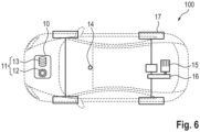
- Fig. 6 shows a motor vehicle 100 with a control device 10 for carrying out the method according to Fig. 1 .
- the control device 10 comprises a computing device 11 with a memory unit 13 and a processor 12.
- the motor vehicle 100 further comprises a drive unit 15 for providing a drive torque.
- the drive unit 15 is connected, for example, by means of a transmission 16 to at least one drive wheel 17, as shown, two drive wheels 17, connected in a torque-transmitting manner. By means of the drive wheels 17, the torque can be converted into propulsion of the motor vehicle 100.
- At least the drive unit 15 of the motor vehicle 100 can be controlled by means of the control device 10 in order to regulate the speed of the motor vehicle 100.
- further components of the motor vehicle 100 can be controlled by means of the control device 10; preferably a braking device and/or a steering system can be controlled by means of the control device 10.
- the motor vehicle 100 is at least a partially autonomous motor vehicle 100, for example a fully autonomous motor vehicle 100.
- the motor vehicle 100 comprises a sensor device 14, which comprises, for example, a camera, a LiDAR sensor and/or a radar sensor.
- the sensor device 14 is also designed to detect the distance 22 to a relevant road user 20.
Landscapes
- Engineering & Computer Science (AREA)
- Transportation (AREA)
- Mechanical Engineering (AREA)
- Automation & Control Theory (AREA)
- Chemical & Material Sciences (AREA)
- Combustion & Propulsion (AREA)
- Human Computer Interaction (AREA)
- Traffic Control Systems (AREA)
- Control Of Driving Devices And Active Controlling Of Vehicle (AREA)
Applications Claiming Priority (1)
| Application Number | Priority Date | Filing Date | Title |
|---|---|---|---|
| DE102023208031.1A DE102023208031A1 (de) | 2023-08-22 | 2023-08-22 | Verfahren zum Steuern eines zumindest teilautonomen Ego-Kraftfahrzeugs |
Publications (1)
| Publication Number | Publication Date |
|---|---|
| EP4512680A1 true EP4512680A1 (fr) | 2025-02-26 |
Family
ID=92043404
Family Applications (1)
| Application Number | Title | Priority Date | Filing Date |
|---|---|---|---|
| EP24190889.6A Pending EP4512680A1 (fr) | 2023-08-22 | 2024-07-25 | Procédé de commande d'un véhicule automobile autonome au moins partiellement autonome |
Country Status (4)
| Country | Link |
|---|---|
| US (1) | US20250065873A1 (fr) |
| EP (1) | EP4512680A1 (fr) |
| CN (1) | CN119502900A (fr) |
| DE (1) | DE102023208031A1 (fr) |
Families Citing this family (1)
| Publication number | Priority date | Publication date | Assignee | Title |
|---|---|---|---|---|
| DE102023204457B3 (de) * | 2023-05-12 | 2024-07-18 | Volkswagen Aktiengesellschaft | Verfahren zur Auswahl eines Zielobjekts für ein Längsführungssystem eines Kraftfahrzeugs, elektronisches Fahrzeugführungssystem für ein Kraftfahrzeug sowie Kraftfahrzeug mit einem elektronischen Fahrzeugführungssystem |
Citations (7)
| Publication number | Priority date | Publication date | Assignee | Title |
|---|---|---|---|---|
| DE102008063579A1 (de) * | 2007-12-21 | 2009-09-03 | Fuji Jukogyo K.K. | Fahrzeug-Fahrsteuersystem |
| DE102012219449A1 (de) * | 2012-10-24 | 2014-04-24 | Bayerische Motoren Werke Aktiengesellschaft | Verfahren zur Geschwindigkeits- und/oder Abstandsregelung bei Kraftfahrzeugen |
| DE102014226462A1 (de) * | 2014-12-18 | 2016-06-23 | Honda Motor Co., Ltd. | Adaptives fahrtsteuerungssystem mit ausscher-vorhersage |
| DE102019129512A1 (de) | 2019-10-31 | 2021-05-06 | Bayerische Motoren Werke Aktiengesellschaft | Fahrassistenzsystem und Fahrassistenzverfahren für ein Fahrzeug |
| WO2022157433A1 (fr) | 2021-01-21 | 2022-07-28 | Psa Automobiles Sa | Procédé et dispositif de contrôle d'un premier véhicule suivant un deuxième véhicule sur une portion de route comprenant un virage |
| JP2022157639A (ja) | 2021-03-31 | 2022-10-14 | 本田技研工業株式会社 | 鞍乗型車両の運転支援システム |
| CN115257734A (zh) | 2022-07-25 | 2022-11-01 | 上汽通用五菱汽车股份有限公司 | 一种自适应巡航控制方法、装置及计算机设备 |
Family Cites Families (11)
| Publication number | Priority date | Publication date | Assignee | Title |
|---|---|---|---|---|
| DE10205225A1 (de) * | 2002-02-08 | 2003-11-20 | Bayerische Motoren Werke Ag | ACC-Spurwechselmodus |
| DE102005036049A1 (de) * | 2005-08-01 | 2007-02-08 | Robert Bosch Gmbh | Verfahren zur Erkennung eines Abbiegevorgangs und Fahrerassistenzsystem für Kraftfahrzeuge |
| US9827986B2 (en) * | 2016-03-29 | 2017-11-28 | Ford Global Technologies, Llc | System and methods for adaptive cruise control based on user defined parameters |
| EP3532801B1 (fr) * | 2016-10-31 | 2020-12-16 | Mobileye Vision Technologies Ltd. | Systèmes et procédés de navigation à des jonctions de voies et des séparations de voies |
| US11001256B2 (en) * | 2018-09-19 | 2021-05-11 | Zoox, Inc. | Collision prediction and avoidance for vehicles |
| US20210101596A1 (en) * | 2019-10-03 | 2021-04-08 | Denso International America, Inc. | System and method for a vehicle adaptive cruise control for a stop-go event |
| US20210261158A1 (en) * | 2020-02-21 | 2021-08-26 | BlueSpace.ai, Inc. | Method for object avoidance during autonomous navigation |
| US11807233B1 (en) * | 2020-12-23 | 2023-11-07 | Zoox, Inc. | Procedurally generated safety system determination |
| WO2023129648A2 (fr) * | 2021-12-30 | 2023-07-06 | ClearMotion, Inc. | Systèmes et procédés de commande de véhicule à l'aide de localisation basée sur le terrain |
| US12515651B2 (en) * | 2022-11-02 | 2026-01-06 | Canoo Technologies Inc. | System and method for target behavior prediction using host prediction in advanced driving assist system (ADAS), autonomous driving (AD), or other applications |
| US20240367650A1 (en) * | 2023-05-03 | 2024-11-07 | Torc Robotics, Inc. | Multi-vehicle adaptive cruise control as a constrained distance bound |
-
2023
- 2023-08-22 DE DE102023208031.1A patent/DE102023208031A1/de active Pending
-
2024
- 2024-07-25 EP EP24190889.6A patent/EP4512680A1/fr active Pending
- 2024-08-14 CN CN202411111401.4A patent/CN119502900A/zh active Pending
- 2024-08-22 US US18/812,045 patent/US20250065873A1/en active Pending
Patent Citations (7)
| Publication number | Priority date | Publication date | Assignee | Title |
|---|---|---|---|---|
| DE102008063579A1 (de) * | 2007-12-21 | 2009-09-03 | Fuji Jukogyo K.K. | Fahrzeug-Fahrsteuersystem |
| DE102012219449A1 (de) * | 2012-10-24 | 2014-04-24 | Bayerische Motoren Werke Aktiengesellschaft | Verfahren zur Geschwindigkeits- und/oder Abstandsregelung bei Kraftfahrzeugen |
| DE102014226462A1 (de) * | 2014-12-18 | 2016-06-23 | Honda Motor Co., Ltd. | Adaptives fahrtsteuerungssystem mit ausscher-vorhersage |
| DE102019129512A1 (de) | 2019-10-31 | 2021-05-06 | Bayerische Motoren Werke Aktiengesellschaft | Fahrassistenzsystem und Fahrassistenzverfahren für ein Fahrzeug |
| WO2022157433A1 (fr) | 2021-01-21 | 2022-07-28 | Psa Automobiles Sa | Procédé et dispositif de contrôle d'un premier véhicule suivant un deuxième véhicule sur une portion de route comprenant un virage |
| JP2022157639A (ja) | 2021-03-31 | 2022-10-14 | 本田技研工業株式会社 | 鞍乗型車両の運転支援システム |
| CN115257734A (zh) | 2022-07-25 | 2022-11-01 | 上汽通用五菱汽车股份有限公司 | 一种自适应巡航控制方法、装置及计算机设备 |
Also Published As
| Publication number | Publication date |
|---|---|
| CN119502900A (zh) | 2025-02-25 |
| DE102023208031A1 (de) | 2025-02-27 |
| US20250065873A1 (en) | 2025-02-27 |
Similar Documents
| Publication | Publication Date | Title |
|---|---|---|
| DE102019124700B4 (de) | Fahrsteuerungsvorrichtung für ein fahrzeug | |
| DE102019134079B4 (de) | Fahrsteuerungsvorrichtung für ein fahrzeug | |
| EP1486933B1 (fr) | Système d' aide à la conduite | |
| EP1077826B1 (fr) | Systeme d'assistance au conducteur et son procede de fonctionnement | |
| DE102004004918B4 (de) | Verfahren zur Kollisions-Warnung bei einem Kraftfahrzeug | |
| EP2734425B1 (fr) | Procédé d'amélioration de la stabilité de conduite | |
| DE102020100342A1 (de) | Fahrsteuerungsvorrichtung für ein fahrzeug | |
| DE102020100343A1 (de) | Fahrsteuerungsvorrichtung für ein fahrzeug | |
| DE102019134871A1 (de) | Fahrzeugsteuerungsvorrichtung für ein fahrzeug | |
| DE102011121487B4 (de) | Vorrichtung und Verfahren zum Betreiben zumindest eines Fahrerassistenzsystems eines Kraftwagens | |
| EP3281830A1 (fr) | Système de commande et procédé de commande destinés à déterminer une trajectoire et à émettre des signaux correspondants ou des erreurs de commande | |
| EP3281831A1 (fr) | Système de commande et procédé de commande destinés à déterminer une probabilité pour un changement de voie de circulation d'un véhicule déboitant | |
| EP1363800B1 (fr) | Dispositif de regulation adaptative de la vitesse d'un vehicule automobile par des operations de direction ou de freinage | |
| DE102014210174B4 (de) | Bestimmen eines kritischen Fahrzeugzustands und einer Fahrzeugmindestentfernung | |
| EP1689615A1 (fr) | Procede et dispositif pour alerter le conducteur d'un vehicule automobile | |
| DE102018130243A1 (de) | Erweitertes Szenario für Autobahnassistenten | |
| WO2006053655A1 (fr) | Procede pour eviter une collision ou pour reduire les consequences d'une collision et dispositif pour realiser ce procede | |
| DE102009048789A1 (de) | Verfahren zur Querführung eines Kraftfahrzeugs | |
| DE102016211208A1 (de) | Fortgeschrittenes Fahrerassistenzverfahren und -system | |
| DE102019134081A1 (de) | Fahrsteuerungsvorrichtung für ein fahrzeug | |
| WO2020052840A1 (fr) | Procédé et dispositif pour faire fonctionner un premier véhicule fonctionnant au moins partiellement de manière automatique | |
| DE102008013988B4 (de) | Verfahren und Vorrichtung zum Durchführen eines Ausweichmanövers | |
| DE102014206344A1 (de) | Ausweichassistent | |
| EP3243717B1 (fr) | Dispositif de commande de véhicule automobile et procédé de fonctionnement du dispositif de commande destiné au guidage autonome d'un véhicule automobile | |
| EP1750236A1 (fr) | Procédé et dispositif de commande d'un système d'assistance d'un conducteur |
Legal Events
| Date | Code | Title | Description |
|---|---|---|---|
| PUAI | Public reference made under article 153(3) epc to a published international application that has entered the european phase |
Free format text: ORIGINAL CODE: 0009012 |
|
| STAA | Information on the status of an ep patent application or granted ep patent |
Free format text: STATUS: THE APPLICATION HAS BEEN PUBLISHED |
|
| AK | Designated contracting states |
Kind code of ref document: A1 Designated state(s): AL AT BE BG CH CY CZ DE DK EE ES FI FR GB GR HR HU IE IS IT LI LT LU LV MC ME MK MT NL NO PL PT RO RS SE SI SK SM TR |
|
| STAA | Information on the status of an ep patent application or granted ep patent |
Free format text: STATUS: REQUEST FOR EXAMINATION WAS MADE |
|
| 17P | Request for examination filed |
Effective date: 20250826 |
|
| RIC1 | Information provided on ipc code assigned before grant |
Ipc: B60W 30/095 20120101AFI20251001BHEP Ipc: B60W 30/16 20200101ALI20251001BHEP Ipc: B60W 30/17 20200101ALI20251001BHEP Ipc: B60W 30/18 20120101ALI20251001BHEP |
|
| GRAP | Despatch of communication of intention to grant a patent |
Free format text: ORIGINAL CODE: EPIDOSNIGR1 |
|
| STAA | Information on the status of an ep patent application or granted ep patent |
Free format text: STATUS: GRANT OF PATENT IS INTENDED |
|
| INTG | Intention to grant announced |
Effective date: 20251113 |
|
| GRAJ | Information related to disapproval of communication of intention to grant by the applicant or resumption of examination proceedings by the epo deleted |
Free format text: ORIGINAL CODE: EPIDOSDIGR1 |
|
| STAA | Information on the status of an ep patent application or granted ep patent |
Free format text: STATUS: REQUEST FOR EXAMINATION WAS MADE |
|
| P01 | Opt-out of the competence of the unified patent court (upc) registered |
Free format text: CASE NUMBER: UPC_APP_0003815_4512680/2026 Effective date: 20260203 |
|
| GRAP | Despatch of communication of intention to grant a patent |
Free format text: ORIGINAL CODE: EPIDOSNIGR1 |
|
| STAA | Information on the status of an ep patent application or granted ep patent |
Free format text: STATUS: GRANT OF PATENT IS INTENDED |
|
| INTC | Intention to grant announced (deleted) | ||
| INTG | Intention to grant announced |
Effective date: 20260317 |