EP4512735A1 - Boîte de stockage à configuration de fixation améliorée - Google Patents
Boîte de stockage à configuration de fixation améliorée Download PDFInfo
- Publication number
- EP4512735A1 EP4512735A1 EP24194461.0A EP24194461A EP4512735A1 EP 4512735 A1 EP4512735 A1 EP 4512735A1 EP 24194461 A EP24194461 A EP 24194461A EP 4512735 A1 EP4512735 A1 EP 4512735A1
- Authority
- EP
- European Patent Office
- Prior art keywords
- main body
- lug
- elongated slits
- storage box
- improved fastening
- Prior art date
- Legal status (The legal status is an assumption and is not a legal conclusion. Google has not performed a legal analysis and makes no representation as to the accuracy of the status listed.)
- Pending
Links
Images


Classifications
-
- B—PERFORMING OPERATIONS; TRANSPORTING
- B65—CONVEYING; PACKING; STORING; HANDLING THIN OR FILAMENTARY MATERIAL
- B65D—CONTAINERS FOR STORAGE OR TRANSPORT OF ARTICLES OR MATERIALS, e.g. BAGS, BARRELS, BOTTLES, BOXES, CANS, CARTONS, CRATES, DRUMS, JARS, TANKS, HOPPERS, FORWARDING CONTAINERS; ACCESSORIES, CLOSURES, OR FITTINGS THEREFOR; PACKAGING ELEMENTS; PACKAGES
- B65D43/00—Lids or covers for rigid or semi-rigid containers
- B65D43/14—Non-removable lids or covers
- B65D43/22—Devices for holding in closed position, e.g. clips
-
- B—PERFORMING OPERATIONS; TRANSPORTING
- B65—CONVEYING; PACKING; STORING; HANDLING THIN OR FILAMENTARY MATERIAL
- B65D—CONTAINERS FOR STORAGE OR TRANSPORT OF ARTICLES OR MATERIALS, e.g. BAGS, BARRELS, BOTTLES, BOXES, CANS, CARTONS, CRATES, DRUMS, JARS, TANKS, HOPPERS, FORWARDING CONTAINERS; ACCESSORIES, CLOSURES, OR FITTINGS THEREFOR; PACKAGING ELEMENTS; PACKAGES
- B65D43/00—Lids or covers for rigid or semi-rigid containers
- B65D43/02—Removable lids or covers
- B65D43/0202—Removable lids or covers without integral tamper element
- B65D43/0204—Removable lids or covers without integral tamper element secured by snapping over beads or projections
-
- B—PERFORMING OPERATIONS; TRANSPORTING
- B65—CONVEYING; PACKING; STORING; HANDLING THIN OR FILAMENTARY MATERIAL
- B65D—CONTAINERS FOR STORAGE OR TRANSPORT OF ARTICLES OR MATERIALS, e.g. BAGS, BARRELS, BOTTLES, BOXES, CANS, CARTONS, CRATES, DRUMS, JARS, TANKS, HOPPERS, FORWARDING CONTAINERS; ACCESSORIES, CLOSURES, OR FITTINGS THEREFOR; PACKAGING ELEMENTS; PACKAGES
- B65D43/00—Lids or covers for rigid or semi-rigid containers
- B65D43/14—Non-removable lids or covers
- B65D43/16—Non-removable lids or covers hinged for upward or downward movement
- B65D43/162—Non-removable lids or covers hinged for upward or downward movement the container, the lid and the hinge being made of one piece
-
- B—PERFORMING OPERATIONS; TRANSPORTING
- B65—CONVEYING; PACKING; STORING; HANDLING THIN OR FILAMENTARY MATERIAL
- B65D—CONTAINERS FOR STORAGE OR TRANSPORT OF ARTICLES OR MATERIALS, e.g. BAGS, BARRELS, BOTTLES, BOXES, CANS, CARTONS, CRATES, DRUMS, JARS, TANKS, HOPPERS, FORWARDING CONTAINERS; ACCESSORIES, CLOSURES, OR FITTINGS THEREFOR; PACKAGING ELEMENTS; PACKAGES
- B65D2251/00—Details relating to container closures
- B65D2251/10—Details of hinged closures
- B65D2251/1016—Means for locking the closure in closed position
- B65D2251/105—The closure having a part fitting over the rim of the container or spout and retained by snapping over integral beads or projections
Definitions
- the present disclosure relates to a storage box. More particularly, the present disclosure relates to a storage box with improved fastening configuration.
- meals can be contained by a disposable food box (e.g., a lunch box, hamburger boxes) which is portable. Due to environmental factors and human health factors, the disposable food box has been improved from a plastic box to a paper box with a wax layer coated thereon, and next, the disposable food box is improved to be made through a pulp molded manner.
- a disposable food box e.g., a lunch box, hamburger boxes
- Due to environmental factors and human health factors, the disposable food box has been improved from a plastic box to a paper box with a wax layer coated thereon, and next, the disposable food box is improved to be made through a pulp molded manner.
- the disposable food box 100 includes a lid 10 and a container 11, and the lid 10 is able to cover the container 11.
- the food box 100 is mainly provided with two triangular lugs 110a on an outer edge of the container 11, and a buckle piece 101 protruding from the outer edge of the lid 10 and corresponding to a gap 110 between the two triangular lugs 110a.
- the buckle piece 101 has two triangle-like clips 101a at both ends of the buckle piece 101.
- the buckle piece 101 of the cover body 10 can be pressed down ( Fig. 1 ) into the gap 110.
- the triangle-like clips 101a of the lid 10 are located below the triangular lugs 110a, and a cross engaging force could be reluctantly provided for stopping against the buckle piece 101 by the triangular lugs 110a.
- One aspect of the present disclosure is to provide a storage box with improved fastening configuration for solving the difficulties mentioned above in the prior art.
- a storage box with improved fastening configuration includes a container portion and a lid portion.
- the container portion includes a lower main body and at least one lug set.
- the lug set includes two lug parts jointly protruding from one side of the lower main body, and a gap defined between the lug parts.
- One side of each of the lug parts is formed with a lower elongated slit, and the lower elongated slits of the lug parts are coaxial with each other, and in communication with the gap.
- the lid portion includes an upper main body movably covered the lower main body, at least one buckle piece bendably connected to one side of the upper main body, and arranged correspondingly to the gap, and two upper elongated slits located opposite to each other, and coaxial with each other.
- Each of the upper elongated slits is located between the upper main body and the at least one buckle piece.
- a storage box with improved fastening configuration includes a container portion and a lid portion.
- the container portion includes a lower main body, a lower recess and at least one lug set.
- the lower recess is formed on one surface of the lower main body.
- the lug sets are respectively located on different sides of the lower main body.
- Each of the lug sets includes two lug parts. The lug parts of each of the lug sets are spaced apart from each other, so that a gap is defined between the lug parts.
- a lower elongated slit is formed on one side of each of the lug parts of each of the lug sets, and the lower elongated slits of the lug parts of each of the lug sets are coaxial with each other and in communication with the corresponding gap between of the lug parts.
- the lid portion includes an upper main body and a plurality of buckle pieces.
- the upper main body removably covers the container portion and the lower recess, and able to be completely detached from the lower main body.
- the buckle pieces are bendably connected to different sides of the upper main body, and respectively corresponding to the gaps of the lug sets.
- Each of the buckle pieces is formed with two upper elongated slits at two opposite sides thereof, and the upper elongated slits of each of the buckle pieces are coaxial with each other.
- the storage box with improved fastening configuration is able to improve the fastening strengths of these fastening configuration, so that the lid portion and the container portion can be quickly fastened together to avoid the object received therein from being exposed and spilled outwardly when being vibrated or squeezed by users.
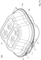
- Fig. 3 is a perspective view of a storage box 100A with improved fastening configuration according to one embodiment of the present disclosure
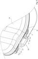
- Fig. 4 is a schematic view of the storage box 100A of Fig. 3 in an open state, and enlarged views of two specific areas in Fig. 4
- the storage box 100A with improved fastening configuration includes a container portion 20, a lid portion 30 and a connection portion 40.
- the container portion 20 includes a lower main body 200, a lower recess 201 and a lug set 202.
- the lower recess 201 is formed on one surface of the lower main body 200.
- the lug set 202 includes two lug parts 21 spaced arranged on one side of the lower main body 200, and a gap 22 formed between the lug parts 21.
- the lug parts 21 jointly protrude from the same side of the lower main body 200, and the gap 22 is defined by the lug parts 21 and the lower main body 200.
- each of the lug parts 21 laterally extends outwards from an outer edge 22a of the side of the lower main body 200.
- One side of each of the lug parts 21 is formed with a lower elongated slit 21a, and the lower elongated slits 21a of the lug parts 21 are coaxial with each other and in communication with the gap 22 formed between the lug parts 21.
- each of the lower elongated slits 21a is partially cut on the lug parts 21, so that one free end portion (also called as a first tail portion 23, hereinafter) of the lug part 21 which is flexible, is defined by the corresponding lower elongated slit 21a and the gap 22.
- the aforementioned lower elongated slits 21a are respectively formed on inner sides of the lug parts 21 which are faced with each other, and the lower elongated slits 21a are connected to the outer edge 22a of the side of the lower main body 200.
- the dimensions of the lower elongated slits 21a are in millimeter-levels.
- the length of the lower elongated slits 21a is, for example, 0.5-0.8 mm. However, there disclosure is not limited thereto.
- each of the lower elongated slits 21a allows the corresponding first tail portion 23 described above to be physically deformed in response to the changes of physically deforming force on one of the lug parts 21, and allows the corresponding first tail portion 23 to be physically rebounded back to its original position when the temporarily deformation is vanished.
- the lid portion 30 includes an upper main body 300, an upper recess 301, a buckle piece 31 and two upper elongated slits 31a.
- the upper main body 300 is flappable on the lower main body 200.
- the upper recess 301 is recessed on one surface of the upper main body 300.
- the disclosure is not limited thereto, in another embodiment, the lid portion 30 may be in a plate shape without the upper recess 301 mentioned above.
- the buckle piece 31 is bendably connected to one side of the upper main body 300, and arranged correspondingly to the gap 22. For example, the buckle piece 31 laterally extends outwards in a lateral direction (e.g., X axis) away from an outer edge 32a of the side of the upper main body 300.
- a lateral direction e.g., X axis
- the upper elongated slits 31a are located opposite to each other, and coaxial with each other. Each of the upper elongated slits 31a is located between the upper main body 300 and the buckle piece 31, in other words, the upper elongated slits 31a separates the upper main body 300 and the buckle piece 31. Specifically, the upper elongated slits 31a are partially cut on the buckle piece 31, respectively, so that two free end portions (also called as second tail portions 33, hereinafter) of the buckle piece 31 which are flexible, are formed. In another embodiment, the upper elongated slits 31a may also be directly formed on the buckle piece 31, rather than being the partition slit between the buckle piece 31 and the upper main body 300.
- each of the upper elongated slits 31a allows the corresponding second tail portion 33 described above to be physically deformed in response to the changes of physically deforming force on the buckle piece 31, and allows the corresponding second tail portion 33 to be physically rebounded back to its original position when the temporarily deformation is vanished.
- the size of the lower main body 200 and the upper main body 300 are approximately the same, and the dimensions of the upper elongated slits 31a are in millimeter-levels.
- the length of the upper elongated slits 31a is, for example, 0.8 mm.
- the connection portion 40 is integrally connected to the container portion 20 and the lid portion 30, and opposite to the lug set 202 so that the lid portion 30 is flappable to the container portion 20.
- each of the lower elongated slits 21a is in a lined shape, and the lower elongated slits 21a are connected to the outer edge 22a of the side of the lower main body 200.
- a long axis direction (e.g., Y axis) of each of the lower elongated slits 21a is parallel to a long axis direction (e.g., Y axis) of the outer edge 22a of the side of the lower main body 200.
- Each of the upper elongated slits 31a is in a lined shape, and the upper elongated slits 31a are connected to the outer edge 32a of the side of the upper main body 300.
- a long axis direction (e.g., Y axis) of each of the upper elongated slits 31a is parallel to a long axis direction (e.g., Y axis) of the outer edge 32a of the side of the upper main body 300.
- the buckle piece 31 is further provided with a broken line 32.
- the broken line 32 is located between the upper elongated slits 31a, and between the upper main body 300 and the buckle piece 31.
- a long axis direction (e.g., Y axis) of the broken line 32 is coaxial with a long axis direction (e.g., Y axis) of each of the upper elongated slits 31a.
- each of the lug parts 21 is provided with a protruding portion 21b.
- the protruding portion 21b protrudes downwardly along Z axis direction for enhancing the structural strength of the lug parts 21.
- One surface of the buckle piece 31 is provided with a protruding portion 31b.
- the protruding portion 31b protrudes downwardly along Z axis direction for enhancing the structural strength of the buckle piece 31.
- One with ordinary skill in the art of the disclosure may appropriately adjust the numbers of the lug set 202 and the buckle piece 31 in time according to the sizes of the container portion 20 and the lid portion 30 or the fastening requirements of multi-sided of the container portion 20 and the lid portion 30.
- the lug sets 202 are respectively located on different sides or the same side of the container portion 20, and the buckle pieces 31 are respectively located on different sides or the same side of the lid portion 30.
- Fig. 5A and Fig. 5B are continuous operation views of the container portion 20 and the lid portion 30 in Fig. 3 being fastened to each other.
- Fig. 6 is an enlarged view of the container portion 20 and the lid portion 30 in Fig. 5B being fastened to each other.
- a user rotates the lid portion 30 to cover the container portion 20 in the direction D1 ( Fig. 5A ), so that the upper recess 301 and the lower recess 201 are in communication together to form a receiving chamber (not shown in figures) capable of receiving an object such as meal, food and likes.
- the storage box 100A can also be implemented as a food box in this embodiment.
- the disclosure is not limited to the usage of the storage box 100A.
- the user bends the buckle piece 31 of the lid portion 30 into the gap 22 of the container portion 20 in the direction D2 ( Fig. 5B ), so that the upper elongated slits 31a and the lower elongated slits 21a are connected to each other, thus, the buckle piece 31 is allowed to be abutted against the lug parts 21, and the lug parts 21 are allowed to be abutted against the buckle piece 31, respectively. More specifically, when the buckle piece 31 is rotated into the gap 22 ( Fig.
- the second tail portions 33 and the first tail portions 23 are collectively physically deformed, that is, when a physically deforming force is applied on the buckle piece 31, the first tail portions 23 of the lug parts 21 are pressed by the second tail portions 33 of the buckle piece 31, and the second tail portions 33 of the buckle piece 31 are pressed by the first tail portions 23 of the lug parts 21.
- the second tail portions 33 are physically rebounded back to its original position when the temporarily deformation is vanished ( Fig. 4 ) so that the second tail portions 33 are snapped into the corresponding lower elongated slits 21a.
- the second tail portions 33 are stopped and positioned limited by the first tail portions 23, and the first tail portions 23 are stopped and positioned limited by the second tail portions 33, respectively.
- the lid portion 30 and the container portion 20 can be quickly fastened together to avoid the object received therein from being exposed and spilled outwardly when being vibrated or squeezed by users.
- the user can quickly open the lid portion 30 from the container portion 20 reversely according to the above sequence ( Fig. 4 ).
- Fig. 7 is a perspective view of a storage box 100B with improved fastening configuration according to one embodiment of the present disclosure.
- Fig. 8 is a schematic view of the storage box 100B of Fig. 7 in an open state.
- the storage box 100B of this embodiment is substantially the same to the storage box 100A of Fig. 3 mentioned above.
- the lid portion 30A is able to be completely detached from the container portion 20A so that the aforementioned connection portion 40 in the embodiment can be omitted.
- the upper main body 300 removably covers the container portion 20A and the lower recess 201, and able to be completely detached from the lower main body 200.
- the lid portion 30A in Fig. 7 is in a plate shape without an upper recess.
- the lower recess 201 is solely defined to be the aforementioned receiving chamber (not shown in figures) by the lid portion 30A and the container portion 20A.
- the container portion 20A further includes a plurality (e.g., two) of lug sets 202.
- the lug sets 202 are respectively located on the different sides of the lower main body 200.
- the lug sets 202 are located on two opposite sides (e.g., long sides) of the lower main body 200.
- the lid portions 30A further includes a plurality (e.g., two) of buckle pieces 31.
- the buckle pieces 31 are respectively located on the different sides of the upper main body 300.
- the buckle pieces 31 are located on two opposite sides of the upper main body 300.
- the buckle pieces 31 are extended in opposite directions (e.g., X axis) away from each other, and the upper elongated slits 31a mentioned above are respectively formed on two opposite sides of each of the buckle pieces 31.
- the storage box with improved fastening configuration is able to improve the fastening strengths of these fastening configuration, so that the lid portion and the container portion can be quickly fastened together to avoid the object received therein from being exposed and spilled outwardly when being vibrated or squeezed by users.
Landscapes
- Engineering & Computer Science (AREA)
- Mechanical Engineering (AREA)
- Closures For Containers (AREA)
Applications Claiming Priority (1)
| Application Number | Priority Date | Filing Date | Title |
|---|---|---|---|
| TW112130489A TWI863503B (zh) | 2023-08-14 | 2023-08-14 | 扣固結構改良之食品盒 |
Publications (1)
| Publication Number | Publication Date |
|---|---|
| EP4512735A1 true EP4512735A1 (fr) | 2025-02-26 |
Family
ID=92424406
Family Applications (1)
| Application Number | Title | Priority Date | Filing Date |
|---|---|---|---|
| EP24194461.0A Pending EP4512735A1 (fr) | 2023-08-14 | 2024-08-14 | Boîte de stockage à configuration de fixation améliorée |
Country Status (4)
| Country | Link |
|---|---|
| US (1) | US12503278B2 (fr) |
| EP (1) | EP4512735A1 (fr) |
| JP (1) | JP3248712U (fr) |
| TW (1) | TWI863503B (fr) |
Citations (3)
| Publication number | Priority date | Publication date | Assignee | Title |
|---|---|---|---|---|
| FR1193761A (fr) * | 1959-11-04 | |||
| DE8028238U1 (de) * | 1980-10-23 | 1981-06-11 | Deltaplastic GmbH & Co KG, 2863 Ritterhude | Verpackung fuer Hamburger |
| US4574951A (en) * | 1984-12-17 | 1986-03-11 | Champion International Corporation | Reclosable package |
Family Cites Families (11)
| Publication number | Priority date | Publication date | Assignee | Title |
|---|---|---|---|---|
| US5094355A (en) * | 1990-12-20 | 1992-03-10 | Mobil Oil Corporation | Hinged-lid food container with sealable compartments employing front and side latching means |
| US5506046A (en) * | 1992-08-11 | 1996-04-09 | E. Khashoggi Industries | Articles of manufacture fashioned from sheets having a highly inorganically filled organic polymer matrix |
| TW230498B (fr) * | 1993-12-13 | 1994-09-11 | ||
| US20090057381A1 (en) * | 2007-08-29 | 2009-03-05 | Chandan Gokhale | Molded paper pulp pizza box |
| US20130327770A1 (en) * | 2012-06-07 | 2013-12-12 | Robert R. Turvey | Container having an arched portion and Lid Therefor |
| US20140263353A1 (en) * | 2013-03-15 | 2014-09-18 | Huhtamaki, Inc. | Carton with foldout partition |
| US10035632B2 (en) * | 2014-05-15 | 2018-07-31 | Kyllburg Technologies, LLC | Food container with forced moisture removal |
| MX2022004715A (es) * | 2019-10-21 | 2022-05-11 | Zume Inc | Contenedores de alimentos que tienen interfaces de cierre. |
| CN210942763U (zh) * | 2019-10-29 | 2020-07-07 | 大千科技(天津)有限公司 | 一种易开启密封吸塑盒 |
| TWI760097B (zh) * | 2021-02-05 | 2022-04-01 | 尚墩股份有限公司 | 具有防非法開啟辨識功能之容器 |
| US11548704B1 (en) * | 2021-09-09 | 2023-01-10 | Cheng Chen Yen | Combined device of a box |
-
2023
- 2023-08-14 TW TW112130489A patent/TWI863503B/zh active
-
2024
- 2024-08-14 US US18/804,429 patent/US12503278B2/en active Active
- 2024-08-14 EP EP24194461.0A patent/EP4512735A1/fr active Pending
- 2024-08-14 JP JP2024002714U patent/JP3248712U/ja active Active
Patent Citations (3)
| Publication number | Priority date | Publication date | Assignee | Title |
|---|---|---|---|---|
| FR1193761A (fr) * | 1959-11-04 | |||
| DE8028238U1 (de) * | 1980-10-23 | 1981-06-11 | Deltaplastic GmbH & Co KG, 2863 Ritterhude | Verpackung fuer Hamburger |
| US4574951A (en) * | 1984-12-17 | 1986-03-11 | Champion International Corporation | Reclosable package |
Also Published As
| Publication number | Publication date |
|---|---|
| US20250058942A1 (en) | 2025-02-20 |
| TW202506502A (zh) | 2025-02-16 |
| JP3248712U (ja) | 2024-10-10 |
| US12503278B2 (en) | 2025-12-23 |
| TWI863503B (zh) | 2024-11-21 |
Similar Documents
| Publication | Publication Date | Title |
|---|---|---|
| US5518133A (en) | Packaging tab | |
| EP4512735A1 (fr) | Boîte de stockage à configuration de fixation améliorée | |
| US9406460B2 (en) | Push switch | |
| JP5846642B2 (ja) | 押釦スイッチ | |
| US2352587A (en) | Pouring spout for containers | |
| JP2947469B2 (ja) | 食品用包装容器の変形防止構造 | |
| CN109153484B (zh) | 带盖容器 | |
| JP3164749U (ja) | 包装箱 | |
| US2178620A (en) | Container | |
| JP2011073721A (ja) | 減容化して再閉鎖可能なブリスターパック | |
| JP6747710B2 (ja) | 粘稠材料用容器の中蓋体 | |
| JP7282336B2 (ja) | 容器のシート取出し口 | |
| CN220810132U (zh) | 食品包装盒 | |
| CN223791937U (zh) | 食品包装盒板 | |
| JP2807051B2 (ja) | 密封用蓋 | |
| JP4409025B2 (ja) | 包装用容器の蓋 | |
| JPH0647769Y2 (ja) | 食品ケース | |
| JP3474480B2 (ja) | 包装容器 | |
| JP2020117254A (ja) | 包装体 | |
| JP2807050B2 (ja) | 密封用蓋 | |
| JPH0733155A (ja) | 包装容器 | |
| WO2012049668A1 (fr) | Contenant comportant un dispositif de fermeture repositionnable | |
| JP2003095302A (ja) | 容器の蓋体 | |
| JP2820449B2 (ja) | 密封用蓋 | |
| KR101807372B1 (ko) | 식품 포장 상자 |
Legal Events
| Date | Code | Title | Description |
|---|---|---|---|
| PUAI | Public reference made under article 153(3) epc to a published international application that has entered the european phase |
Free format text: ORIGINAL CODE: 0009012 |
|
| STAA | Information on the status of an ep patent application or granted ep patent |
Free format text: STATUS: REQUEST FOR EXAMINATION WAS MADE |
|
| 17P | Request for examination filed |
Effective date: 20240814 |
|
| AK | Designated contracting states |
Kind code of ref document: A1 Designated state(s): AL AT BE BG CH CY CZ DE DK EE ES FI FR GB GR HR HU IE IS IT LI LT LU LV MC ME MK MT NL NO PL PT RO RS SE SI SK SM TR |