EP4512765A1 - Arbeitsplattform mit erweiterungsdeck und arbeitsstufe - Google Patents
Arbeitsplattform mit erweiterungsdeck und arbeitsstufe Download PDFInfo
- Publication number
- EP4512765A1 EP4512765A1 EP24208111.5A EP24208111A EP4512765A1 EP 4512765 A1 EP4512765 A1 EP 4512765A1 EP 24208111 A EP24208111 A EP 24208111A EP 4512765 A1 EP4512765 A1 EP 4512765A1
- Authority
- EP
- European Patent Office
- Prior art keywords
- work
- work platform
- deck
- platform
- legs
- Prior art date
- Legal status (The legal status is an assumption and is not a legal conclusion. Google has not performed a legal analysis and makes no representation as to the accuracy of the status listed.)
- Pending
Links
Images



Classifications
-
- B—PERFORMING OPERATIONS; TRANSPORTING
- B66—HOISTING; LIFTING; HAULING
- B66F—HOISTING, LIFTING, HAULING OR PUSHING, NOT OTHERWISE PROVIDED FOR, e.g. DEVICES WHICH APPLY A LIFTING OR PUSHING FORCE DIRECTLY TO THE SURFACE OF A LOAD
- B66F11/00—Lifting devices specially adapted for particular uses not otherwise provided for
- B66F11/04—Lifting devices specially adapted for particular uses not otherwise provided for for movable platforms or cabins, e.g. on vehicles, permitting workmen to place themselves in any desired position for carrying out required operations
-
- B—PERFORMING OPERATIONS; TRANSPORTING
- B66—HOISTING; LIFTING; HAULING
- B66F—HOISTING, LIFTING, HAULING OR PUSHING, NOT OTHERWISE PROVIDED FOR, e.g. DEVICES WHICH APPLY A LIFTING OR PUSHING FORCE DIRECTLY TO THE SURFACE OF A LOAD
- B66F11/00—Lifting devices specially adapted for particular uses not otherwise provided for
- B66F11/04—Lifting devices specially adapted for particular uses not otherwise provided for for movable platforms or cabins, e.g. on vehicles, permitting workmen to place themselves in any desired position for carrying out required operations
- B66F11/042—Lifting devices specially adapted for particular uses not otherwise provided for for movable platforms or cabins, e.g. on vehicles, permitting workmen to place themselves in any desired position for carrying out required operations actuated by lazy-tongs mechanisms or articulated levers
-
- B—PERFORMING OPERATIONS; TRANSPORTING
- B66—HOISTING; LIFTING; HAULING
- B66F—HOISTING, LIFTING, HAULING OR PUSHING, NOT OTHERWISE PROVIDED FOR, e.g. DEVICES WHICH APPLY A LIFTING OR PUSHING FORCE DIRECTLY TO THE SURFACE OF A LOAD
- B66F13/00—Common constructional features or accessories
-
- B—PERFORMING OPERATIONS; TRANSPORTING
- B66—HOISTING; LIFTING; HAULING
- B66F—HOISTING, LIFTING, HAULING OR PUSHING, NOT OTHERWISE PROVIDED FOR, e.g. DEVICES WHICH APPLY A LIFTING OR PUSHING FORCE DIRECTLY TO THE SURFACE OF A LOAD
- B66F17/00—Safety devices, e.g. for limiting or indicating lifting force
- B66F17/006—Safety devices, e.g. for limiting or indicating lifting force for working platforms
Definitions
- This disclosure pertains to self-propelled aerial work platform apparatus, particularly small size self-propelled scissors lifts which are controllable and moveable by an operator from the work platform.
- Scissors lifts are in widespread use in warehouses, construction sites and various other job sites. With the increasing use of low-level aerial work platforms to perform elevated work tasks in safer and more productive methods, there is a need for means to work through small overhead openings.
- a typical application is the need to work on utility services such as electric and communication cables, water and gas pipes and the like which are secured to structural ceilings having drop ceilings suspended below the utilities. Since access openings which may be made in the drop ceiling are typically less than 24" wide, the work platform guardrails restrict elevation of the platform above the suspended drop ceiling thereby preventing the worker from conveniently reaching the utilities above the drop ceiling for installation, replacement or repair.
- SHU 5 device offered by Man Lift Manufacturing Co. for a self-propelled scissor lift.
- the attachment allows a worker to reach higher but replaces the existing slide out deck and therefore not only eliminates this advantageous feature but also causes the apparatus to be significantly longer thereby making it less maneuverable in tight spaces, restriction for entering a freight elevator and for loading onto a delivery vehicle. Such devices are heavy causing the lift capacity to be reduced.
- the attachment is relatively expensive and not instantly available or readily installed.
- a platform of the type having an extension deck for use in aerial work platform apparatus comprises a main deck and an extension deck with guardrails and an attached moveable step. Guardrails having raiseable upper sections are provided on the extension deck. The step is moveable from a work position in which it is horizontally oriented above the extension deck to a storage position when not in use.
- This work platform is particularly adapted for use on small aerial work apparatus which has a self-propelled chassis and mechanism such as a scissors lift on the chassis for elevating the platform to a work position. Operator controls are provided on the work platform for positioning the apparatus and for elevating and lowering the work platform.
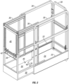
- the work platform 10 is of generally rectangular configuration and includes a main deck 20, an extension deck 30 and a storable step 40 particularly useful on small aerial work apparatus such as a scissors lift.
- the main deck 20 of the platform includes longitudinally extending structural members 22 affixed to and supporting a generally flat floor or bottom 24, spaced side guardrails 26 and an access gate 28 at one end.
- the extension deck 30 includes longitudinally extending structural members 32 supporting a flat floor or bottom 34.
- the structural members 32 of the extension deck 30 are slideably received between and supported by the structural members 22 of the main deck such that the floor 34 of the extension deck is slightly above the floor 24 of the main deck 20. It will be noted from Figs.
- the bottom 34 of the extension deck 30 has a cutout area 35 at the end facing the gate so that the operator can stand on the floor 24 of the main deck and manually extend and retract the extension deck 30 when desired.
- Spaced side and end guardrails 36, 38 of the extension deck 30 are sized and connected as shown such that the extension deck and its guardrails may be stowed above the main deck 20. Stops (not shown) are provided as is conventional to define the safe limits of travel of the extension deck 30.
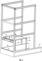
- Upper sections of the side guardrails on the extension deck may be lowered from the Fig. 1 position to the Fig. 2 position by telescopically sliding the upper guardrail support legs into or alongside the guardrail support legs immediately below.
- a moveable step 40 for safety purposes is preferably of rectangular configuration and extends substantially the full width of the extension deck 30 to provide an elevated step up work platform when needed.
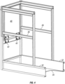
- the edge of the step nearest the end of the extension deck is affixed, preferably by a pair of hinges 42, to support structure such as a guardrail cross brace 38 of the extension deck such that the unhinged end of the step 40 may be lifted from a horizontally extending working elevation above the floor 34 of the extension deck to a vertically extending storage position at the end of the extension deck when not in use.
- the step 40 includes pivotally connected support legs 44 preferably having configuration such as short projections at the ends thereof to be received in retainers such as positioning pockets 46 in the floor 34 of the extension deck when the step is in its horizontal work position. Applicable safety and operating instructions can be displayed on the floor 34 of the extension deck 30 to be visible when the step 40 is in its horizontally extended position and/or on the underside of the step to be visible when the step is in its vertical storage position.
- Upper moveable guardrail sections of the extension deck 30 are provided to protect a worker when standing on the step 40.
- the upper guardrail sections may be manually lifted from lowered positions in which their vertical legs are preferably telescopically stored inside or alongside vertical legs of the lower extension deck guardrail sections.
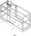
- the upper sections of the guardrails 36 may be retained in either the stored position or in the work position by T handle pull pins 39 ( Figs. 5 - 10 ) which engage with holes in the vertically extending guardrail legs.
- powered means may be provided to assist lifting the upper guardrail sections to operable position.
- the step 40 is connected along a pivot axis to supporting structure on the extension deck such as a guardrail cross brace 38 by a hinge or hinges 42 and the step support legs 44 are preferably pivotally connected at 45 to the step 40 to be located closely alongside the step support surface when the step is pivotally raised to its stored location.
- the step 40 and legs 44 may be secured to a guardrail by temporary fastening means such as snap retainers, the step 40 then occupying its stored position between the vertically extending corner guardrail legs. Alternatively, it may be preferred to swing the step to a storage position below the hinges 42 instead of above.
- An operator control station 50 is provided in any suitable location on the extension deck 30 as seen in Figs. 5 and 6 .
- Additional embodiments of the invention can comprise one or more features of the following embodiments either taken alone or in an arbitrary combination unless defined otherwise.
- a work platform for use in aerial work platform apparatus comprising a main deck, an extension deck supported on said main deck, said extension deck having a floor, guardrails and a work step, said step being moveable from a work position in which it is horizontally oriented above said floor to a storage position when not in use.
- the work platform may include at least one hinge connecting said step to support structure on said extension deck.
- the work platform may further include at least one step support leg and a hinge connecting said step to said support leg.
- the work platform may include two of said support legs and hinges, said hinges connecting said support legs to spaced sides of said step thereby permitting said legs to pivot alongside said step from a step support position into a vertically extending storage position of said step and legs.
- said floor of said extension deck may include retainers for securing ends of said legs when said step is in said work position.
- said guardrails on said extension deck may include upper sections moveable from lowered storage positions to elevated safe height positions.
- said upper guardrail sections may include legs telescopically received in legs of lower guardrail sections.
- an aerial work platform apparatus may comprise:
- the apparatus may include at least one hinge connecting said step to a horizontally extending cross brace at one end of said extension deck.
- the apparatus may further include at least one step support leg and a hinge connecting said step to said support leg.
- the apparatus may include two of said support legs and hinges connecting said support legs to spaced sides of said step thereby permitting said legs to pivot alongside said step from a step support position into a vertically extending storage position of said step and legs.
- said floor of said extension deck includes retainers for securing ends of said support legs in position when said step is in said work position.
- said retainers comprise apertures for receiving portions of said support legs when said step is in said work position.
- said guardrails on said extension deck include upper sections moveable from lowered storage positions to elevated safe height positions.
- said upper guardrail sections include legs telescopically received in vertically extending legs of lower guardrail sections.
- the above described embodiment provides a significant improvement to more easily allow workers to minimize re-positioning of the aerial work platform and step up to better reach into and above small access openings such as those in drop ceilings to work on utilities suspended from structural ceilings.
Landscapes
- Engineering & Computer Science (AREA)
- Structural Engineering (AREA)
- Life Sciences & Earth Sciences (AREA)
- Geology (AREA)
- Mechanical Engineering (AREA)
- Forklifts And Lifting Vehicles (AREA)
Applications Claiming Priority (3)
| Application Number | Priority Date | Filing Date | Title |
|---|---|---|---|
| US201862663465P | 2018-04-27 | 2018-04-27 | |
| US16/275,854 US20190330034A1 (en) | 2018-04-27 | 2019-02-14 | Work platform with extension deck and work step |
| EP19170465.9A EP3560887B1 (de) | 2018-04-27 | 2019-04-23 | Arbeitsplattform mit erweiterungsdeck und arbeitsstufe |
Related Parent Applications (1)
| Application Number | Title | Priority Date | Filing Date |
|---|---|---|---|
| EP19170465.9A Division EP3560887B1 (de) | 2018-04-27 | 2019-04-23 | Arbeitsplattform mit erweiterungsdeck und arbeitsstufe |
Publications (1)
| Publication Number | Publication Date |
|---|---|
| EP4512765A1 true EP4512765A1 (de) | 2025-02-26 |
Family
ID=66248550
Family Applications (2)
| Application Number | Title | Priority Date | Filing Date |
|---|---|---|---|
| EP19170465.9A Active EP3560887B1 (de) | 2018-04-27 | 2019-04-23 | Arbeitsplattform mit erweiterungsdeck und arbeitsstufe |
| EP24208111.5A Pending EP4512765A1 (de) | 2018-04-27 | 2019-04-23 | Arbeitsplattform mit erweiterungsdeck und arbeitsstufe |
Family Applications Before (1)
| Application Number | Title | Priority Date | Filing Date |
|---|---|---|---|
| EP19170465.9A Active EP3560887B1 (de) | 2018-04-27 | 2019-04-23 | Arbeitsplattform mit erweiterungsdeck und arbeitsstufe |
Country Status (3)
| Country | Link |
|---|---|
| US (1) | US20190330034A1 (de) |
| EP (2) | EP3560887B1 (de) |
| CA (1) | CA3038609A1 (de) |
Families Citing this family (8)
| Publication number | Priority date | Publication date | Assignee | Title |
|---|---|---|---|---|
| CA2944316C (en) * | 2015-10-07 | 2023-12-19 | Charles Frederick Harmon | Cage assembly for use with pivotal gangway |
| US12252380B1 (en) | 2018-04-27 | 2025-03-18 | California Manufacturing & Engineering Company, Llc | Work platform having attached movable work step |
| MX2021007206A (es) * | 2018-12-17 | 2021-12-15 | Terex South Dakota Inc | Conjunto de placa soporte de acceso y conjunto de mango para una plataforma de trabajo aerea de un vehículo. |
| US11512477B2 (en) * | 2019-11-22 | 2022-11-29 | The Boeing Company | Telescoping guardrail/flip door |
| US20210276849A1 (en) * | 2020-03-06 | 2021-09-09 | Oshkosh Corporation | Adjustable Platform Rail Systems and Methods |
| CN114684758B (zh) * | 2022-03-28 | 2024-07-02 | 法兰泰克(常州)工程机械有限公司 | 一种带提供额外工作高度的登高台和高空作业平台 |
| PL73695Y1 (pl) * | 2024-03-22 | 2024-12-02 | Hk Montage Spolka Z Ograniczona Odpowiedzialnoscia | Platforma robocza |
| CN120717387A (zh) * | 2024-03-28 | 2025-09-30 | 特雷克斯南达科他州有限公司 | 车辆高空作业平台的进出台面组件 |
Citations (6)
| Publication number | Priority date | Publication date | Assignee | Title |
|---|---|---|---|---|
| US3664458A (en) * | 1971-01-20 | 1972-05-23 | Lorance E Sterns | Ladder scaffold vehicle |
| US4009903A (en) * | 1972-06-22 | 1977-03-01 | Manspeaker Robert O | Retractable seat |
| US4883145A (en) * | 1988-02-12 | 1989-11-28 | Deltatto Charles D | Ergonomic aerial basket |
| EP2479135A1 (de) * | 2011-01-21 | 2012-07-25 | California Manufacturing Engineering Company LLC | Hubarbeitsvorrichtung mit seitlich versetzter Arbeitsbühne |
| EP3156025A1 (de) * | 2015-10-14 | 2017-04-19 | Palfinger Tail Lifts GmbH | Hubbühne |
| CN207618972U (zh) * | 2017-10-30 | 2018-07-17 | 苏州如意物流设备有限公司 | 一种带座椅的升降平台 |
Family Cites Families (77)
| Publication number | Priority date | Publication date | Assignee | Title |
|---|---|---|---|---|
| US366365A (en) * | 1887-07-12 | Alexander | ||
| US543196A (en) * | 1895-07-23 | Leg for bath-tubs or other articles | ||
| US1439388A (en) * | 1921-06-06 | 1922-12-19 | Benedict E Willett | Stepladder |
| US1579115A (en) * | 1923-10-23 | 1926-03-30 | Everett B Kebbe | Bed |
| US1887283A (en) * | 1928-12-18 | 1932-11-08 | Brabson Frank | Furniture support |
| US2257211A (en) * | 1938-05-09 | 1941-09-30 | American Car & Foundry Co | Seat |
| US2581488A (en) * | 1947-07-29 | 1952-01-08 | Keltner Robert Neil | Retractable step assembly |
| US2850080A (en) * | 1955-10-31 | 1958-09-02 | Meaney & Madaloni Inc | Kneeling attachment for portable chairs |
| US3017968A (en) * | 1957-01-14 | 1962-01-23 | Mcmahon William Horice | Scaffold |
| US3030166A (en) * | 1959-07-02 | 1962-04-17 | William C Richards | Combination cabinet and stepladder |
| US3112010A (en) * | 1961-10-10 | 1963-11-26 | Patent Scaffolding Co Inc | Safety ladder |
| US3181711A (en) * | 1963-07-19 | 1965-05-04 | Samuel W Stockton | Wallboard positioning device |
| US3395648A (en) * | 1965-06-04 | 1968-08-06 | Fed Engineering Company | Moving sidewalk |
| US3265156A (en) * | 1965-06-29 | 1966-08-09 | Alfred D Jacobs | Platform means with adjustable companion units |
| US3596735A (en) * | 1969-10-30 | 1971-08-03 | Howard H Denier | Portable elevator working and load-lifting platform |
| US4064999A (en) * | 1976-07-07 | 1977-12-27 | Simon Young | Adjustable building panel scaffold |
| US4157129A (en) * | 1978-04-26 | 1979-06-05 | Christopher Gordon W | Stabbing board assembly |
| US4558847A (en) * | 1980-10-22 | 1985-12-17 | Coates Management Pty. Ltd. | Patient lifting table |
| US4356887A (en) * | 1980-12-29 | 1982-11-02 | Up-Right, Inc. | Rotatable platform assembly |
| US4494465A (en) * | 1983-11-01 | 1985-01-22 | Fick Jr Charles M | Table for use with automobile trunks and the like |
| US5094515A (en) * | 1990-09-26 | 1992-03-10 | Low Jeanie S | Folding step for cabinet doors |
| US5158023A (en) * | 1991-02-21 | 1992-10-27 | Allen Tony L | Scaffold table for sheet rock finishers |
| US5085290A (en) * | 1991-02-21 | 1992-02-04 | Guirlinger Edward C | Foldaway stool mounted to inside of cabinet door |
| FR2684934B1 (fr) * | 1991-12-12 | 1994-03-18 | Faure Automobile Bertrand | Siege mobile pour vehicule. |
| US5547205A (en) * | 1993-02-09 | 1996-08-20 | Do Rosario Sousa De Cabedo; Maria | Luggage cart with attached seat |
| US5297844A (en) * | 1993-07-02 | 1994-03-29 | Haustein Herbert H | Removable cab and stand for all terrain vehicles |
| US5358067A (en) * | 1993-09-15 | 1994-10-25 | Lance Camper Mfg. Corp. | Folding step for mounting above an interior corner between a wall and a floor |
| US5381872A (en) * | 1994-04-04 | 1995-01-17 | Peruzzi; Victor M. | Scaffold system |
| US5746034B1 (en) * | 1994-12-30 | 2000-10-17 | Steelcase Inc | Partition system |
| US5513900A (en) * | 1995-01-24 | 1996-05-07 | Iglesias; Carlos A. | Chair stabilizing device |
| JP3292626B2 (ja) * | 1995-06-22 | 2002-06-17 | アイシン精機株式会社 | 車両用シート |
| CA2177508C (en) * | 1996-05-28 | 2001-03-20 | George Leslie Lawson | Mobile lift assembly |
| US6044961A (en) * | 1998-04-15 | 2000-04-04 | Hine; Laurence J. | Apparatus for displaying advertising information on conveyor panels |
| US6044927A (en) * | 1998-09-23 | 2000-04-04 | Zefer Operations, Inc. | Work platform lift machine with scissor lift mechanism employing telescopable electro-mechanical based lift actuation arrangement |
| US5967255A (en) * | 1998-11-25 | 1999-10-19 | Young; Daniel D. | Step stool attachment |
| US6105721A (en) * | 1999-08-06 | 2000-08-22 | Haynes; Rusty | Accessory for use with an ATV |
| US6431632B1 (en) * | 2001-06-04 | 2002-08-13 | General Motors Corporation | Automobile seat assembly attachment structure |
| CA2440788C (en) * | 2003-09-12 | 2012-01-03 | Jean-Paul Fredette | Motorized scaffold with displaceable worker support platform |
| US7448470B2 (en) * | 2005-09-06 | 2008-11-11 | Aluminum Ladder Company | Maintenance stand |
| US20070187184A1 (en) * | 2006-02-10 | 2007-08-16 | Nasuti Michelle L | Scissors lift utility tray assembly |
| US20070262633A1 (en) * | 2006-05-09 | 2007-11-15 | Stoffer Jan R | Chair accessory and method of using |
| US20080105498A1 (en) * | 2006-06-12 | 2008-05-08 | Genie Industries, Inc. | Joint assembly and related methods |
| US8490747B2 (en) * | 2006-06-30 | 2013-07-23 | Werner Co. | Telescoping project tray |
| US20160069094A1 (en) * | 2006-08-05 | 2016-03-10 | Donald F. Lombardi | Mason's adjustable chimney-platform arrangement |
| US7434521B2 (en) * | 2006-08-05 | 2008-10-14 | Lombardi Donald F | Mason's adjustable chimney-platform arrangement |
| US20080149420A1 (en) * | 2006-12-01 | 2008-06-26 | Cheatham Daniel P | Vehicle mountable elevating platform |
| US20080302601A1 (en) * | 2007-06-06 | 2008-12-11 | Andrew Baker | Lift assembly |
| US20090218166A1 (en) * | 2008-02-28 | 2009-09-03 | Timothy Newton | Scaffold auxiliary shelf |
| CN101700863B (zh) * | 2009-02-05 | 2013-05-01 | 崔侃 | 结构紧凑型剪叉式高空作业举升车 |
| US8505684B1 (en) * | 2009-02-05 | 2013-08-13 | Marc Bogue | Aerial work platform apparatus and method |
| KR101392354B1 (ko) * | 2009-10-16 | 2014-05-07 | 오티스 엘리베이터 컴파니 | 이동가능한 측방향 패널 부재들을 갖는 승객 컨베이어 |
| FR2955571B1 (fr) * | 2010-01-26 | 2012-04-27 | Haulotte Group | Preparateur de commande |
| GB2479202A (en) * | 2010-04-01 | 2011-10-05 | James Lawrence Weston | Collapsible scaffolding tower |
| US8651237B2 (en) * | 2010-06-09 | 2014-02-18 | Richard D Pulliam | Worker support cage for front end loader bucket |
| US8479882B2 (en) * | 2010-07-07 | 2013-07-09 | Aluminum Ladder Company | Cement industry gangway |
| US8800717B2 (en) * | 2010-07-28 | 2014-08-12 | General Tree Corporation | Mobile scaffolding units with extendible gantry platform and methods of using same |
| GB2487737B (en) * | 2011-02-01 | 2013-05-01 | Teletower Com Ltd | Guardrail for an elevated working platform |
| WO2012109444A2 (en) * | 2011-02-09 | 2012-08-16 | Baillargeon Paul D | Warning and message delivery and logging system utilizable in the monitoring of fall arresting and prevention devices and method of same |
| US8801095B2 (en) * | 2012-06-08 | 2014-08-12 | Philip D Moody | Deployable chair for stroller coupling |
| US9617788B2 (en) * | 2013-06-28 | 2017-04-11 | John W. Goodson | Cabinet mounted step stool |
| DK2937300T3 (en) * | 2014-04-23 | 2016-12-12 | Rexnord Flattop Europe S R L | Chain belt to articles |
| US9938732B1 (en) * | 2015-03-12 | 2018-04-10 | Boston Whaler, Inc. | Articulating staging system for manufacturing |
| US20170202727A1 (en) * | 2016-01-18 | 2017-07-20 | Highlander Inventions Corp. | Folding step for use with mobility device |
| CN205575519U (zh) * | 2016-03-29 | 2016-09-14 | 石东风 | 一种新型剪刀式高空作业车 |
| US9883741B2 (en) * | 2016-05-02 | 2018-02-06 | Vincent Demasi, III | Foldable step system |
| GB2553137B (en) * | 2016-08-25 | 2019-11-20 | Bluesky Solutions Ltd | Anti-entrapment device for scissor lifts |
| EP3573921B1 (de) * | 2017-01-25 | 2024-01-03 | JLG Industries, Inc. | Hubebühne mit druckbasiertes lastmesssystem |
| US11383963B2 (en) * | 2017-03-03 | 2022-07-12 | Jlg Industries, Inc. | Obstacle detection system for an aerial work platform |
| US20180354762A1 (en) * | 2017-06-09 | 2018-12-13 | Kenneth R Altizer | Mobile, personal lift with a translatable platform |
| USD856623S1 (en) * | 2017-07-13 | 2019-08-13 | Jcb Access Limited | Scissor lift |
| USD859773S1 (en) * | 2017-07-13 | 2019-09-10 | Jcb Access Limited | Scissor lift |
| US11007944B1 (en) * | 2017-11-27 | 2021-05-18 | Hwh Corporation | Automatic railing for a retractable stairway |
| JP6655636B2 (ja) * | 2018-02-09 | 2020-02-26 | 本田技研工業株式会社 | 台車利用の搬送設備 |
| US11112060B2 (en) * | 2018-04-05 | 2021-09-07 | California Manufacturing & Engineering Co Llc | Mobile work machine with fluid drip retention |
| EP3947248B1 (de) * | 2019-04-05 | 2025-08-20 | Oshkosh Corporation | Plattformsteuerkasten |
| US11773606B2 (en) * | 2019-07-18 | 2023-10-03 | The Boeing Company | Flip door-to-guardrail |
| US10918203B1 (en) * | 2019-09-06 | 2021-02-16 | Itc Incorporated | Pedestal leg assembly |
-
2019
- 2019-02-14 US US16/275,854 patent/US20190330034A1/en active Pending
- 2019-04-01 CA CA3038609A patent/CA3038609A1/en active Pending
- 2019-04-23 EP EP19170465.9A patent/EP3560887B1/de active Active
- 2019-04-23 EP EP24208111.5A patent/EP4512765A1/de active Pending
Patent Citations (6)
| Publication number | Priority date | Publication date | Assignee | Title |
|---|---|---|---|---|
| US3664458A (en) * | 1971-01-20 | 1972-05-23 | Lorance E Sterns | Ladder scaffold vehicle |
| US4009903A (en) * | 1972-06-22 | 1977-03-01 | Manspeaker Robert O | Retractable seat |
| US4883145A (en) * | 1988-02-12 | 1989-11-28 | Deltatto Charles D | Ergonomic aerial basket |
| EP2479135A1 (de) * | 2011-01-21 | 2012-07-25 | California Manufacturing Engineering Company LLC | Hubarbeitsvorrichtung mit seitlich versetzter Arbeitsbühne |
| EP3156025A1 (de) * | 2015-10-14 | 2017-04-19 | Palfinger Tail Lifts GmbH | Hubbühne |
| CN207618972U (zh) * | 2017-10-30 | 2018-07-17 | 苏州如意物流设备有限公司 | 一种带座椅的升降平台 |
Also Published As
| Publication number | Publication date |
|---|---|
| EP3560887B1 (de) | 2024-10-23 |
| US20190330034A1 (en) | 2019-10-31 |
| EP3560887A1 (de) | 2019-10-30 |
| CA3038609A1 (en) | 2019-10-27 |
Similar Documents
| Publication | Publication Date | Title |
|---|---|---|
| EP3560887B1 (de) | Arbeitsplattform mit erweiterungsdeck und arbeitsstufe | |
| US20240151046A1 (en) | Adjustable platform rail systems and methods | |
| EP1846631B1 (de) | Vorrichtung für den einsatz beim bau von gebäuden | |
| EP2479135B1 (de) | Hubarbeitsvorrichtung mit seitlich versetzter Arbeitsbühne | |
| AU553169B2 (en) | Portable lift with ladder | |
| US11247886B2 (en) | Personnel basket for overhead cranes | |
| US12516570B2 (en) | Ladder-mounted material lift | |
| US3902700A (en) | Step ladder supported portable bridge-crane structure for lifting materials to the top of an adjacent building | |
| JPH02500829A (ja) | エアブリツジ | |
| KR20180079418A (ko) | 로딩 플랫폼 | |
| AU2016306542B2 (en) | Deck for scaffold | |
| US20240300792A1 (en) | Work platform with extension deck and work step, and related methods | |
| US9550661B2 (en) | Self-contained, portable and self-supporting scaffolding kit | |
| US9222306B2 (en) | Crane access staircase and mounting system | |
| US11873196B2 (en) | Mobile crane having a folding walking platform | |
| US12252380B1 (en) | Work platform having attached movable work step | |
| AU649856B2 (en) | Cantilever scaffold device | |
| US2778694A (en) | Mobile swinging lift platform equipment | |
| EP1785548A2 (de) | Gerüstturm mit integrierten Sicherheitsmassnahmen | |
| AU2013203442A1 (en) | Screen Module | |
| JPH0743168U (ja) | 高所作業車における乗降用梯子構造 | |
| JPS6136457A (ja) | 足場装置 | |
| GB2432573A (en) | Apparatus for permitting overhead access for a workperson | |
| JPH10140957A (ja) | 伸縮型梯子 | |
| JPH0428697A (ja) | 工事用リフト |
Legal Events
| Date | Code | Title | Description |
|---|---|---|---|
| PUAI | Public reference made under article 153(3) epc to a published international application that has entered the european phase |
Free format text: ORIGINAL CODE: 0009012 |
|
| STAA | Information on the status of an ep patent application or granted ep patent |
Free format text: STATUS: THE APPLICATION HAS BEEN PUBLISHED |
|
| AC | Divisional application: reference to earlier application |
Ref document number: 3560887 Country of ref document: EP Kind code of ref document: P |
|
| AK | Designated contracting states |
Kind code of ref document: A1 Designated state(s): AL AT BE BG CH CY CZ DE DK EE ES FI FR GB GR HR HU IE IS IT LI LT LU LV MC MK MT NL NO PL PT RO RS SE SI SK SM TR |
|
| STAA | Information on the status of an ep patent application or granted ep patent |
Free format text: STATUS: REQUEST FOR EXAMINATION WAS MADE |
|
| 17P | Request for examination filed |
Effective date: 20250826 |