EP4512990A2 - Dégagement de filetage - Google Patents
Dégagement de filetage Download PDFInfo
- Publication number
- EP4512990A2 EP4512990A2 EP24219918.0A EP24219918A EP4512990A2 EP 4512990 A2 EP4512990 A2 EP 4512990A2 EP 24219918 A EP24219918 A EP 24219918A EP 4512990 A2 EP4512990 A2 EP 4512990A2
- Authority
- EP
- European Patent Office
- Prior art keywords
- thread
- female portion
- length
- female
- mounting sleeve
- Prior art date
- Legal status (The legal status is an assumption and is not a legal conclusion. Google has not performed a legal analysis and makes no representation as to the accuracy of the status listed.)
- Pending
Links
Images


Classifications
-
- E—FIXED CONSTRUCTIONS
- E21—EARTH OR ROCK DRILLING; MINING
- E21B—EARTH OR ROCK DRILLING; OBTAINING OIL, GAS, WATER, SOLUBLE OR MELTABLE MATERIALS OR A SLURRY OF MINERALS FROM WELLS
- E21B17/00—Drilling rods or pipes; Flexible drill strings; Kellies; Drill collars; Sucker rods; Cables; Casings; Tubings
- E21B17/02—Couplings; joints
- E21B17/04—Couplings; joints between rod or the like and bit or between rod and rod or the like
- E21B17/042—Threaded
- E21B17/0426—Threaded with a threaded cylindrical portion, e.g. for percussion rods
-
- E—FIXED CONSTRUCTIONS
- E21—EARTH OR ROCK DRILLING; MINING
- E21B—EARTH OR ROCK DRILLING; OBTAINING OIL, GAS, WATER, SOLUBLE OR MELTABLE MATERIALS OR A SLURRY OF MINERALS FROM WELLS
- E21B17/00—Drilling rods or pipes; Flexible drill strings; Kellies; Drill collars; Sucker rods; Cables; Casings; Tubings
- E21B17/02—Couplings; joints
-
- E—FIXED CONSTRUCTIONS
- E21—EARTH OR ROCK DRILLING; MINING
- E21B—EARTH OR ROCK DRILLING; OBTAINING OIL, GAS, WATER, SOLUBLE OR MELTABLE MATERIALS OR A SLURRY OF MINERALS FROM WELLS
- E21B17/00—Drilling rods or pipes; Flexible drill strings; Kellies; Drill collars; Sucker rods; Cables; Casings; Tubings
- E21B17/02—Couplings; joints
- E21B17/04—Couplings; joints between rod or the like and bit or between rod and rod or the like
- E21B17/042—Threaded
Definitions
- Percussion drilling is used to create a long borehole via a plurality of elongate drill string rods coupled together end-to-end by interconnected male and female threads.
- a drill bit may be connected to a single rod.
- the well-established technique breaks rock by hammering impacts transferred from the rock drill bit to the rock at the bottom of the borehole.
- the rock drill bit is mounted at one end of the drill string via a male thread on the endmost drill string rod to a female thread on the drill bit.
- the energy required to break the rock is generated by a hydraulically driven piston that contacts the end of the drill string (via a shank adaptor) to create a stress (or shock) wave that propagates through the drill string to a drill bit.
- Conventional threaded joints are described in US 4,332,502 ; US 4,398,756 ; US 4,687,368 and DE 2800887 .
- Threaded joints in the percussive drilling tool such as those between drill string rods and between the endmost drill string rod and the drill bit are subjected to bending forces during drilling from the stress waves that propagate the drill string. These bending moments fatigue the threaded joints and lead to breakage within the threaded portion of the joint. Eventually the stress will cause the threaded joint to get worn out and eventually fail.
- a female portion to form part of a thread joint for a percussive drilling tool comprising: a mounting sleeve having an axial end, wherein the mounting sleeve surrounds an internal cavity having an axial inner wall at the opposing end of the mounting sleeve compared to the axial end; wherein the mounting sleeve has at least one substantially cylindrical internally threaded section having a length L 1 , a thread entrance towards the axial end and a thread exit towards the axial inner wall; a thread clearance section positioned between the axial inner wall and the thread exit having a length L 2 and a diameter D 1 ; a guiding section positioned between the thread entrance and the axial end of the sleeve having a length, L 3 ; characterized in that: 0 mm ⁇ L 3 -L 2 ⁇ 12 mm. More preferably, 5
- this reduces the stress in the female portion of the threaded joint, meaning the risk of breakages in the female portion is decreased. Furthermore, if the stress in the female portion is increased then the diameter of the male threaded part can be increased which improves the performance of the percussive drilling tool.
- L 2 /L 1 > 0.01x D 1 .
- by increasing the ratio of the length of the thread clearance area compared to the length of the threaded section means that the stress in thread clearance area decreases.
- L 2 / L 1 > 26%, more preferably L 2 / L 1 > 32%.
- increasing the ratio of the length of the thread clearance area compared to the length of the threaded section means that the stress in thread clearance area decreases.
- L 2 / L 1 ⁇ 65%, more preferably ⁇ 50%.
- this provides sufficient length in the threaded section to achieve a secure threaded connection.
- L 2 / D 1 ⁇ 65%, more preferably ⁇ 50%.
- this enables a secure threaded connection.
- the female portion is a drill bit. In an alternative embodiment, the female portion is a female end of a drill string rod.
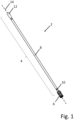
- FIG 1 shows a percussive drilling tool 2 whereby a drill rod 4 is threadedly coupled to a drill bit 6 of conventional design.
- the percussive drilling tool 2 is especially used for top hammer drilling. Shockwaves generated by a surface piston (not shown) are translated through the mated surfaces from the drill rod 4 to the drill bit 6.
- the drill rod 4 comprises an axially extending main length section 8 that is terminated at one end by a male end 10 and at a second opposite end by a female end 12 having a longitudinal axis 14.
- the drill rod 4 is capable of being coupled end-to-end with other further drill rods to form a drill string (not shown) via another thread joint.
- Figure 2 shows that alternatively the drill bit 6 may be connected to a single drill rod 4 having two male ends 10.
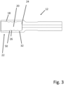
- Figure 3 shows a cross section of the female end 12 of the drill rod 4 having a mounting sleeve 18 and an internal cavity 20, which is a hollow space, for receiving the male end 10 of the drill rod.
- Figure 4 shows a cross section of the drill bit 6 comprising an axially forwardmost drill head 16 of convention design for example comprising a rock crushing means, most typically this is a plurality of wear resistant cutting buttons projecting axially forward from the drill head (not shown); a mounting sleeve 18 that comprises an axially extending internal cavity 20 for receiving the male end 10 of the drill rod 4.
- the present invention relates to a special design for a female portion 22 that forms part of a thread joint for a percussive drilling tool 2.
- the female portion 22 could be either the female end 12 on the drill rod 4 or the drill bit 6.
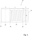
- Figure 5 shows a cross section of an internal profile of the cavity 20 of the female portion 22, in other words figure 5 is an enlargement of the interior of figure 3 or figure 4 .
- the cavity 20 has an axial inner wall 24 for abutment with a male end 10 of a drill rod 4. Further, the cavity 20 has at least one substantially cylindrical internally threaded section 26 having a thread entrance 28 at the axially opposite end compared to the axial inner wall 24 and a thread exit 30 nearer to the axial inner wall 24.
- the threaded section 26 has a length, L 1 , which is defined as the length between the thread entrance 28 and the thread exit 30.
- the cavity 20 of the female portion 22 also has a thread clearance section 32 positioned between the axial inner wall 24 and the threaded section 26.
- the thread clearance section 32 is circumferential concave recess.
- the thread clearance section 32 has a length, L 2 , which is defined as the length between the thread exit 30 and the axial inner wall 24.
- the thread clearance section has a diameter, D 1 .
- the guiding section 50 has a length, L 3 , which is defined as the length between the thread entrance 28 and an axial end 52 of the sleeve 18.
- the guiding section 50 can either be a constant diameter across the whole of the guiding section 50 or it could optionally be stepped so that it has at least two different diameters.
- L 3 - L 2 for female portions 22 according to the present invention is ⁇ 12 mm, more preferably ⁇ 11.5 mm, even more preferably ⁇ 11 mm.
- L 3 - L 2 for female portions 22 according to the present invention is >0 mm, more preferably >5 mm, even more preferably >7 mm.
- L 1 is between 25-56 mm, more preferably between 30-45 mm.
- L 2 / L 1 > 26%, more preferably >32%.
- L 2 / L 1 ⁇ 65%, more preferably ⁇ 50%.
- L 2 / D 1 > 30%, more preferably >38%.
- L 2 / D 1 ⁇ 65%, more preferably ⁇ 50%.
- the female portion 22 is used for forming a thread joint 34 for a percussive drilling tool 2 wherein there is a bottom contact, as opposed to a shoulder contact, between female portion 22 and the male end 10 of the adjoining rod. In other words, there is contact between the axial inner wall 24 on the female portion and the male end 10 of the adjoining rod 4.
- Table 1 shows a summary of stress measurements for prior art and inventive female portions 22, it can clearly be seen that the stress in the region of the thread clearance is lower for the inventive samples.
- Table 1 Summary of stress measurements Example D 1 (mm) L 3 -L 2 (mm) Stress (MPa) in the region of the thread clearance on the female portion of a threaded joint. 1 (prior art) 33.1 12.7 305 2 (invention) 33.1 11.0 290 3 (prior art) 36.5 14.3 300 4 (invention) 36.5 10.5 275
Landscapes
- Engineering & Computer Science (AREA)
- Geology (AREA)
- Life Sciences & Earth Sciences (AREA)
- Mining & Mineral Resources (AREA)
- Physics & Mathematics (AREA)
- Environmental & Geological Engineering (AREA)
- Fluid Mechanics (AREA)
- Mechanical Engineering (AREA)
- General Life Sciences & Earth Sciences (AREA)
- Geochemistry & Mineralogy (AREA)
- Earth Drilling (AREA)
- Percussive Tools And Related Accessories (AREA)
- Dowels (AREA)
- Materials For Medical Uses (AREA)
Applications Claiming Priority (3)
| Application Number | Priority Date | Filing Date | Title |
|---|---|---|---|
| EP20183128.6A EP3933165A1 (fr) | 2020-06-30 | 2020-06-30 | Dégagement de filetage |
| PCT/EP2021/067808 WO2022002911A1 (fr) | 2020-06-30 | 2021-06-29 | Dégagement de fil |
| EP21737073.3A EP4172455B1 (fr) | 2020-06-30 | 2021-06-29 | Dégagement de filetage |
Related Parent Applications (1)
| Application Number | Title | Priority Date | Filing Date |
|---|---|---|---|
| EP21737073.3A Division EP4172455B1 (fr) | 2020-06-30 | 2021-06-29 | Dégagement de filetage |
Publications (2)
| Publication Number | Publication Date |
|---|---|
| EP4512990A2 true EP4512990A2 (fr) | 2025-02-26 |
| EP4512990A3 EP4512990A3 (fr) | 2025-05-07 |
Family
ID=71409170
Family Applications (3)
| Application Number | Title | Priority Date | Filing Date |
|---|---|---|---|
| EP20183128.6A Withdrawn EP3933165A1 (fr) | 2020-06-30 | 2020-06-30 | Dégagement de filetage |
| EP21737073.3A Active EP4172455B1 (fr) | 2020-06-30 | 2021-06-29 | Dégagement de filetage |
| EP24219918.0A Pending EP4512990A3 (fr) | 2020-06-30 | 2021-06-29 | Dégagement de filetage |
Family Applications Before (2)
| Application Number | Title | Priority Date | Filing Date |
|---|---|---|---|
| EP20183128.6A Withdrawn EP3933165A1 (fr) | 2020-06-30 | 2020-06-30 | Dégagement de filetage |
| EP21737073.3A Active EP4172455B1 (fr) | 2020-06-30 | 2021-06-29 | Dégagement de filetage |
Country Status (13)
| Country | Link |
|---|---|
| US (1) | US20230272678A1 (fr) |
| EP (3) | EP3933165A1 (fr) |
| JP (1) | JP7733683B2 (fr) |
| KR (1) | KR20230028299A (fr) |
| CN (1) | CN115698463A (fr) |
| BR (1) | BR112022026893A2 (fr) |
| CA (1) | CA3179275A1 (fr) |
| CL (1) | CL2022003779A1 (fr) |
| MX (1) | MX2022016467A (fr) |
| PE (1) | PE20230563A1 (fr) |
| PL (1) | PL4172455T3 (fr) |
| WO (1) | WO2022002911A1 (fr) |
| ZA (1) | ZA202212574B (fr) |
Citations (3)
| Publication number | Priority date | Publication date | Assignee | Title |
|---|---|---|---|---|
| DE2800887A1 (de) | 1977-01-11 | 1978-07-13 | Padley & Venables Ltd | Aus loesbar miteinander verbundenen elementen bestehendes bohrgestaenge |
| US4398756A (en) | 1980-09-15 | 1983-08-16 | Vallourec, S. A. | Cylindro-conical pipe joint |
| US4687368A (en) | 1985-04-04 | 1987-08-18 | Santrade Limited | Thread structure for percussion rock drilling |
Family Cites Families (21)
| Publication number | Priority date | Publication date | Assignee | Title |
|---|---|---|---|---|
| US3537738A (en) * | 1968-04-15 | 1970-11-03 | Sandvikens Jernverks Ab | Drill rod for long hole drilling in the ground |
| SE459681B (sv) * | 1985-01-07 | 1989-07-24 | Santrade Ltd | Borrelement foer slagborrning |
| SE469603B (sv) * | 1988-07-08 | 1993-08-02 | Sandvik Ab | Gaengfoerband |
| SE505073C2 (sv) * | 1994-07-19 | 1997-06-23 | Sandvik Ab | Gängförband för slående borrning |
| SE516651C2 (sv) * | 1999-11-26 | 2002-02-05 | Sandvik Ab | Gängförband för slående borrning, en handel och en hondel |
| SE516874C2 (sv) * | 1999-11-26 | 2002-03-19 | Sandvik Ab | Gängförband för slående borrning och handel ingående i gängförbandet |
| SE0000701L (sv) * | 2000-03-02 | 2001-06-25 | Sandvik Ab | Gängförband och bergborrelement för slående borrning |
| SE522221C2 (sv) * | 2001-10-12 | 2004-01-27 | Sandvik Ab | Gängförband för slående bergborrning |
| SE520077C2 (sv) * | 2002-06-27 | 2003-05-20 | Sandvik Ab | Handel, borrkrona och gängförband för slående bergborrning |
| US7210710B2 (en) * | 2004-03-01 | 2007-05-01 | Omsco, Inc. | Drill stem connection |
| JP4954542B2 (ja) * | 2005-12-09 | 2012-06-20 | 三菱マテリアル株式会社 | 掘削ロッド、掘削ビット及び掘削工具 |
| WO2007133150A1 (fr) * | 2006-05-17 | 2007-11-22 | Sandvik Intellectual Property Ab | Marteau supérieur pour forage de roche, tige de forage et manchon d'accouplement |
| SE531459C2 (sv) * | 2006-05-17 | 2009-04-14 | Sandvik Intellectual Property | Hondel samt förfarande för tillverkning av hondelar |
| US9885214B2 (en) * | 2009-07-14 | 2018-02-06 | Ptech Drilling Tubulars, Llc | Threaded tool joint connection |
| EP2383420B1 (fr) * | 2010-04-29 | 2012-06-20 | Sandvik Intellectual Property AB | Trépan pour perçage de roche à percussion |
| US9239122B2 (en) * | 2012-05-22 | 2016-01-19 | Single Buoy Moorings, Inc. | Pipe connection |
| US9643262B2 (en) * | 2013-07-25 | 2017-05-09 | Kennametal Inc. | Coupling mechanism for cutting tool |
| EP2845992B1 (fr) * | 2013-09-09 | 2016-01-13 | Sandvik Intellectual Property AB | Train de tiges de forage avec couplage résistant à la flexion |
| EP4386247A3 (fr) * | 2015-05-22 | 2024-09-25 | Sandvik Intellectual Property AB | Tige de forage ou adaptateur avec accouplement à ergot renforcé |
| EP3095955A1 (fr) * | 2015-05-22 | 2016-11-23 | Sandvik Intellectual Property AB | Extrémité de couplage filetée pour composant de train de tiges |
| CA2977964C (fr) * | 2017-03-13 | 2023-07-04 | 2010990 Alberta Ltd. | Raccord filete dote de filetage femelle et male pour tubulaires |
-
2020
- 2020-06-30 EP EP20183128.6A patent/EP3933165A1/fr not_active Withdrawn
-
2021
- 2021-06-29 MX MX2022016467A patent/MX2022016467A/es unknown
- 2021-06-29 JP JP2022580423A patent/JP7733683B2/ja active Active
- 2021-06-29 BR BR112022026893A patent/BR112022026893A2/pt unknown
- 2021-06-29 PE PE2022002973A patent/PE20230563A1/es unknown
- 2021-06-29 EP EP21737073.3A patent/EP4172455B1/fr active Active
- 2021-06-29 EP EP24219918.0A patent/EP4512990A3/fr active Pending
- 2021-06-29 KR KR1020227045169A patent/KR20230028299A/ko active Pending
- 2021-06-29 CN CN202180040928.0A patent/CN115698463A/zh active Pending
- 2021-06-29 WO PCT/EP2021/067808 patent/WO2022002911A1/fr not_active Ceased
- 2021-06-29 PL PL21737073.3T patent/PL4172455T3/pl unknown
- 2021-06-29 CA CA3179275A patent/CA3179275A1/fr active Pending
- 2021-06-29 US US18/013,215 patent/US20230272678A1/en active Pending
-
2022
- 2022-11-17 ZA ZA2022/12574A patent/ZA202212574B/en unknown
- 2022-12-27 CL CL2022003779A patent/CL2022003779A1/es unknown
Patent Citations (4)
| Publication number | Priority date | Publication date | Assignee | Title |
|---|---|---|---|---|
| DE2800887A1 (de) | 1977-01-11 | 1978-07-13 | Padley & Venables Ltd | Aus loesbar miteinander verbundenen elementen bestehendes bohrgestaenge |
| US4332502A (en) | 1977-01-11 | 1982-06-01 | Padley & Venables Limited | Apparatus for use in drilling |
| US4398756A (en) | 1980-09-15 | 1983-08-16 | Vallourec, S. A. | Cylindro-conical pipe joint |
| US4687368A (en) | 1985-04-04 | 1987-08-18 | Santrade Limited | Thread structure for percussion rock drilling |
Also Published As
| Publication number | Publication date |
|---|---|
| EP4172455B1 (fr) | 2024-12-25 |
| EP3933165A1 (fr) | 2022-01-05 |
| PL4172455T3 (pl) | 2025-03-03 |
| EP4172455A1 (fr) | 2023-05-03 |
| PE20230563A1 (es) | 2023-04-04 |
| KR20230028299A (ko) | 2023-02-28 |
| WO2022002911A1 (fr) | 2022-01-06 |
| CN115698463A (zh) | 2023-02-03 |
| CL2022003779A1 (es) | 2023-05-19 |
| JP7733683B2 (ja) | 2025-09-03 |
| MX2022016467A (es) | 2023-02-01 |
| AU2021298830A1 (en) | 2023-02-02 |
| EP4172455C0 (fr) | 2024-12-25 |
| JP2023531271A (ja) | 2023-07-21 |
| ZA202212574B (en) | 2025-06-25 |
| US20230272678A1 (en) | 2023-08-31 |
| BR112022026893A2 (pt) | 2023-01-24 |
| EP4512990A3 (fr) | 2025-05-07 |
| CA3179275A1 (fr) | 2022-01-06 |
Similar Documents
| Publication | Publication Date | Title |
|---|---|---|
| US10584545B2 (en) | Drill string with bend resistant coupling | |
| US7185721B2 (en) | Male portion, drill bit and threaded joint for percussive rock drilling | |
| EP4041980B1 (fr) | Ensemble de forage protégé par une épaule | |
| EP4172455B1 (fr) | Dégagement de filetage | |
| AU2021298830B2 (en) | Thread clearance | |
| US11808086B2 (en) | Drill string rod | |
| OA21076A (en) | Thread clearance. | |
| EP4183975B1 (fr) | Pas de filetage | |
| OA21684A (en) | Thread pitch | |
| CA3147685C (fr) | Ensemble de forage protege par un epaulement | |
| EP3819458B1 (fr) | Couplage femelle de train de forage à percussion renforcé | |
| OA20696A (en) | Shoulder protected drilling assembly. |
Legal Events
| Date | Code | Title | Description |
|---|---|---|---|
| PUAI | Public reference made under article 153(3) epc to a published international application that has entered the european phase |
Free format text: ORIGINAL CODE: 0009012 |
|
| STAA | Information on the status of an ep patent application or granted ep patent |
Free format text: STATUS: THE APPLICATION HAS BEEN PUBLISHED |
|
| AC | Divisional application: reference to earlier application |
Ref document number: 4172455 Country of ref document: EP Kind code of ref document: P |
|
| AK | Designated contracting states |
Kind code of ref document: A2 Designated state(s): AL AT BE BG CH CY CZ DE DK EE ES FI FR GB GR HR HU IE IS IT LI LT LU LV MC MK MT NL NO PL PT RO RS SE SI SK SM TR |
|
| REG | Reference to a national code |
Ref country code: DE Ref legal event code: R079 Free format text: PREVIOUS MAIN CLASS: E21B0017042000 Ipc: E21B0017020000 |
|
| PUAL | Search report despatched |
Free format text: ORIGINAL CODE: 0009013 |
|
| AK | Designated contracting states |
Kind code of ref document: A3 Designated state(s): AL AT BE BG CH CY CZ DE DK EE ES FI FR GB GR HR HU IE IS IT LI LT LU LV MC MK MT NL NO PL PT RO RS SE SI SK SM TR |
|
| RIC1 | Information provided on ipc code assigned before grant |
Ipc: E21B 17/042 20060101ALI20250331BHEP Ipc: E21B 17/02 20060101AFI20250331BHEP |
|
| STAA | Information on the status of an ep patent application or granted ep patent |
Free format text: STATUS: REQUEST FOR EXAMINATION WAS MADE |
|
| 17P | Request for examination filed |
Effective date: 20251107 |