EP4513038A1 - Rotationsverdichter und verfahren zur herstellung eines rotationsverdichters - Google Patents
Rotationsverdichter und verfahren zur herstellung eines rotationsverdichters Download PDFInfo
- Publication number
- EP4513038A1 EP4513038A1 EP23811746.9A EP23811746A EP4513038A1 EP 4513038 A1 EP4513038 A1 EP 4513038A1 EP 23811746 A EP23811746 A EP 23811746A EP 4513038 A1 EP4513038 A1 EP 4513038A1
- Authority
- EP
- European Patent Office
- Prior art keywords
- recessed portion
- discharge hole
- height
- facing surface
- axis
- Prior art date
- Legal status (The legal status is an assumption and is not a legal conclusion. Google has not performed a legal analysis and makes no representation as to the accuracy of the status listed.)
- Pending
Links
Images


Classifications
-
- F—MECHANICAL ENGINEERING; LIGHTING; HEATING; WEAPONS; BLASTING
- F04—POSITIVE - DISPLACEMENT MACHINES FOR LIQUIDS; PUMPS FOR LIQUIDS OR ELASTIC FLUIDS
- F04C—ROTARY-PISTON, OR OSCILLATING-PISTON, POSITIVE-DISPLACEMENT MACHINES FOR LIQUIDS; ROTARY-PISTON, OR OSCILLATING-PISTON, POSITIVE-DISPLACEMENT PUMPS
- F04C18/00—Rotary-piston pumps specially adapted for elastic fluids
- F04C18/30—Rotary-piston pumps specially adapted for elastic fluids having the characteristics covered by two or more of groups F04C18/02, F04C18/08, F04C18/22, F04C18/24, F04C18/48, or having the characteristics covered by one of these groups together with some other type of movement between co-operating members
- F04C18/34—Rotary-piston pumps specially adapted for elastic fluids having the characteristics covered by two or more of groups F04C18/02, F04C18/08, F04C18/22, F04C18/24, F04C18/48, or having the characteristics covered by one of these groups together with some other type of movement between co-operating members having the movement defined in group F04C18/08 or F04C18/22 and relative reciprocation between the co-operating members
- F04C18/356—Rotary-piston pumps specially adapted for elastic fluids having the characteristics covered by two or more of groups F04C18/02, F04C18/08, F04C18/22, F04C18/24, F04C18/48, or having the characteristics covered by one of these groups together with some other type of movement between co-operating members having the movement defined in group F04C18/08 or F04C18/22 and relative reciprocation between the co-operating members with vanes reciprocating with respect to the outer member
-
- F—MECHANICAL ENGINEERING; LIGHTING; HEATING; WEAPONS; BLASTING
- F04—POSITIVE - DISPLACEMENT MACHINES FOR LIQUIDS; PUMPS FOR LIQUIDS OR ELASTIC FLUIDS
- F04C—ROTARY-PISTON, OR OSCILLATING-PISTON, POSITIVE-DISPLACEMENT MACHINES FOR LIQUIDS; ROTARY-PISTON, OR OSCILLATING-PISTON, POSITIVE-DISPLACEMENT PUMPS
- F04C23/00—Combinations of two or more pumps, each being of rotary-piston or oscillating-piston type, specially adapted for elastic fluids; Pumping installations specially adapted for elastic fluids; Multi-stage pumps specially adapted for elastic fluids
- F04C23/008—Hermetic pumps
-
- F—MECHANICAL ENGINEERING; LIGHTING; HEATING; WEAPONS; BLASTING
- F04—POSITIVE - DISPLACEMENT MACHINES FOR LIQUIDS; PUMPS FOR LIQUIDS OR ELASTIC FLUIDS
- F04C—ROTARY-PISTON, OR OSCILLATING-PISTON, POSITIVE-DISPLACEMENT MACHINES FOR LIQUIDS; ROTARY-PISTON, OR OSCILLATING-PISTON, POSITIVE-DISPLACEMENT PUMPS
- F04C29/00—Component parts, details or accessories of pumps or pumping installations, not provided for in groups F04C18/00 - F04C28/00
- F04C29/12—Arrangements for admission or discharge of the working fluid, e.g. constructional features of the inlet or outlet
- F04C29/124—Arrangements for admission or discharge of the working fluid, e.g. constructional features of the inlet or outlet with inlet and outlet valves specially adapted for rotary or oscillating piston pumps
- F04C29/126—Arrangements for admission or discharge of the working fluid, e.g. constructional features of the inlet or outlet with inlet and outlet valves specially adapted for rotary or oscillating piston pumps of the non-return type
- F04C29/128—Arrangements for admission or discharge of the working fluid, e.g. constructional features of the inlet or outlet with inlet and outlet valves specially adapted for rotary or oscillating piston pumps of the non-return type of the elastic type, e.g. reed valves
Definitions
- the present disclosure relates to a rotary compressor and a method for manufacturing a rotary compressor.
- a rotary compressor that compresses a refrigerant by a rotor disposed eccentrically with respect to a rotary shaft in a compression chamber is known (for example, refer to PTL 1).
- the rotary compressor disclosed in PTL 1 forms a thin portion by digging down an upper surface of an upper bearing and forms a discharge port penetrating the thin portion toward a cylinder chamber.
- the rotary compressor disclosed in PTL 1 achieves high pump efficiency by shortening a discharge port to reduce a volume.
- the discharge port is provided at a bottom portion of a recess formed by digging down the upper surface of the upper bearing, and thus there is a possibility that refrigerant gas discharged from the discharge port collides with an end surface of the recess and large pressure loss occurs.
- a distance from a discharge port to an end surface of a recess is short, so that pressure loss significantly occurs.
- the present disclosure has been made in view of such circumstances, and an object thereof is to provide a rotary compressor and a method for manufacturing a rotary compressor capable of suppressing pressure loss of a refrigerant discharged from a discharge valve accommodated in a recess formed in a bearing.
- a rotary compressor of the present disclosure including a housing that has a tubular portion extending in a vertical direction along an axis, a compression portion that is accommodated in the housing and compresses a refrigerant, and a drive portion that is accommodated in the housing and drives the compression portion by rotating a rotary shaft extending along the axis, in which the compression portion has a piston rotor that is fixed to the rotary shaft and rotates eccentrically with respect to the axis, a cylinder that accommodates the piston rotor, a pair of bearings that rotatably support the rotary shaft around the axis, are disposed to sandwich the cylinder along the axis, and form a compression chamber accommodating the piston rotor, and a discharge valve that is attached to one of the pair of bearings and opens and closes a discharge hole discharging the refrigerant compressed in the compression chamber, a recess that accommodates the discharge valve is formed on a facing surface facing the
- the rotary compressor including a housing that has a tubular portion extending in a vertical direction along an axis, a compression portion that is accommodated in the housing and compresses a refrigerant, and a drive portion that is accommodated in the housing and drives the compression portion by rotating a rotary shaft extending along the axis, in which the compression portion has a piston rotor that is fixed to the rotary shaft and rotates eccentrically with respect to the axis, a cylinder that accommodates the piston rotor, a pair of bearings that rotatably support the rotary shaft around the axis, are disposed to sandwich the cylinder along the axis, and form a compression chamber accommodating the piston rotor, and a discharge valve that is attached to one of the pair of bearings and opens and closes a discharge hole discharging the refrigerant compressed in the compression chamber, the method including a step of forming a recess that accommodates the
- a rotary compressor and a method for manufacturing a rotary compressor capable of suppressing pressure loss of a refrigerant discharged from a discharge valve accommodated in a recess formed in a bearing.
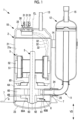
- a rotary compressor 1 is a sealed-type electric rotary compressor used in, for example, an air conditioner or a refrigerating apparatus.
- the rotary compressor 1 includes a compressor body 10 and an accumulator 12.
- the accumulator 12 is connected to the compressor body 10 via a suction pipe 11.
- the compressor body 10 includes an approximately cylindrical housing 2, a rotary shaft 3, an electric motor (drive portion) 5, and a rotary compression portion 6.
- a rotational axis CL of the rotary shaft 3 coincides with a central axis of the housing 2.
- the rotary shaft 3 is disposed such that an extending direction thereof is an up-down direction, and rotates around the rotational axis CL in the housing 2.
- the housing 2 is a sealed-type and extends in the up-down direction.
- the housing 2 includes a main body portion (tubular portion) 21 that has a cylindrical shape extending in a vertical direction VD along the rotational axis CL, and an upper cover portion 22 and a lower cover portion 23 that close upper and lower openings of the main body portion 21.
- a plurality of leg portions 7 are fixed below the main body portion 21.
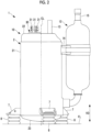
- Each of the leg portions 7 is disposed in a circumferential direction of the main body portion 21 at a predetermined angle interval. As shown in Fig. 2 , each of the leg portions 7 is fixed to an installation surface FL with an antivibration rubber 8 sandwiched therebetween.
- the housing 2 is formed with an opening portion 24 at a position facing an outer peripheral surface of a cylinder 60 in a side wall lower portion.
- a suction port 25 that communicates to a predetermined position in the cylinder is formed at a position facing the opening portion 24.
- An oil reservoir for storing a lubricant is formed in a bottom portion of the hou sing 2.
- a liquid surface of the oil reservoir at a time of initial enclosure of oil is locat ed above the rotary compression portion 6.
- the rotary compression portio n 6 is driven in the oil reservoir.
- a discharge pipe 13 and a terminal block 30 are provided in the upper cover portion 22.
- the discharge pipe 13 penetrates the upper cover portion 22 in a thickness direction, has a lower portion disposed in the housing 2, and has an upper portion disposed outside the housing 2.
- the discharge pipe 13 discharges the compressed refrigerant to the outside of the housing 2.
- the terminal block 30 is provided with three power supply terminals 31 that supply power to an electric motor 5.
- the power supply terminals 31 are supplied with three-phase power from an inverter device (not shown).
- the accumulator 12 is used to gas-liquid-separate the refrigerant before supplying the refrigerant to the compressor body 10.
- the accumulator 12 has an approximately cylindrical shape and is fixed to an outer peripheral surface of the housing 2 via a bracket 14.
- An inlet pipe 15 for introducing a refrigerant guided from an evaporator (not shown) is provided at an upper portion of the accumulator 12.
- the suction pipe 11 for sucking the refrigerant inside the accumulator 12 into the compressor body 10 is connected to the accumulator 12.
- the suction pipe 11 is connected to the suction port 25 through the opening portion 24 of the housing 2.
- the accumulator 12 supplies the gas phase refrigerant to the rotary compression portion 6 via the suction pipe 11.
- the electric motor 5 is accommodated in a central portion of the housing 2 in the up-down direction.
- the electric motor 5 includes a rotor 51 and a stator 52.
- the rotor 51 is fixed to an outer peripheral surface of the rotary shaft 3 and is disposed above the rotary compression portion 6.
- the stator 52 is disposed to surround an outer peripheral surface of the rotor 51 and is fixed to an inner surface 21a of the main body portion 21 of the housing 2.
- Power is supplied to the stator 52 from each of the power supply terminals 31 via wiring 32.
- the electric motor 5 drives the rotary compression portion 6 by rotating the rotary shaft 3 with power supplied from the power supply terminal 31.
- the rotary compression portion 6 is a device that is accommodated in the housing 2 and compresses a refrigerant.
- the rotary compression portion 6 is disposed in a state of being sandwiched from above and below by an upper bearing 4A and a lower bearing 4B.
- Each of the upper bearing 4A and the lower bearing 4B is formed of a metallic material and is fixed to the cylinder 60 configuring the rotary compression portion 6 by bolts 61.
- the rotary shaft 3 is rotatably supported around the rotational axis CL by the upper bearing 4A and the lower bearing 4B.
- the rotary compression portion 6 is disposed at the bottom portion in the housing 2 below the electric motor 5.
- the rotary compression portion 6 includes the upper bearing 4A, the lower bearing 4B, the cylinder 60, an eccentric shaft portion 62, a piston rotor 63, and a discharge valve 64 (refer to Fig. 3 ).
- the cylinder 60 is formed with a compression chamber 60A, a suction hole 60B, and a discharge hole (not shown).
- the compression chamber 60A is formed inside the cylinder 60.
- the piston rotor 63 is accommodated in the compression chamber 60A.
- the upper bearing 4A and the lower bearing 4B are disposed to sandwich the cylinder 60 along the rotational axis CL to form the compression chamber 60A that accommodates the piston rotor 63.
- the rotary compression portion 6 is fixed to the inner surface 21a of the main body portion 21 of the housing 2.
- the upper bearing 4A sandwiching the cylinder 60 is fixed to the inner surface 21a of the main body portion 21 of the housing 2.
- the upper bearing 4A is fixed by performing plug welding at a plurality of locations in a circumferential direction of the housing 2.
- plug welding shrink fitting, cold fitting, or the like may be used.
- the eccentric shaft portion 62 is provided at a lower end portion of the rotary shaft 3 and is provided inside the piston rotor 63 in a state of being offset (eccentric) in a direction orthogonal to the central axis of the rotary shaft 3.
- the piston rotor 63 has a cylindrical shape with an outer diameter smaller than an inner diameter of the cylinder 60, is disposed inside the cylinder 60, and is fixed in a state of being mounted to an outer periphery of the eccentric shaft portion 62.
- the piston rotor 63 rotates eccentrically with respect to the rotational axis CL as the rotary shaft 3 rotates.
- the suction hole 60B is a hole for guiding the refrigerant into the cylinder 60, and is formed in a direction orthogonal to the rotational axis CL.
- a high-pressure refrigerant discharged from a discharge hole 4Aa (refer to Fig. 4 ) formed in the cylinder 60 is guided into a space formed between a discharge cover 65 and the upper bearing 4A, and then guided to an internal space of the housing 2 via a discharge hole (not shown) provided in the discharge cover 65.
- the above-described rotary compressor 1 operates as follows.
- the refrigerant guided from the evaporator (not shown) is taken into the accumulator 12 via the inlet pipe 15.
- the refrigerant is gas-liquid-separated in the accumulator 12, and the gas phase thereof is guided to the rotary compression portion 6 via the suction pipe 11.
- the refrigerant is guided to the compression chamber 60A via the suction hole 60B.
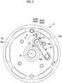
- Fig. 3 is a plan view of the upper bearing 4A of the rotary compression portion 6 as viewed from above along the rotational axis CL.
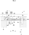
- Fig. 4 is a cross-sectional view taken along line A-A of the rotary compression portion 6 shown in Fig. 3.
- Figs. 3 and 4 show a state in which the discharge cover 65 is removed from the upper bearing 4A.
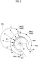
- Fig. 5 is a partially enlarged view of a vicinity of the discharge hole 4Aa of the rotary compression portion 6 shown in Fig. 3 .
- the discharge valve 64 is attached to the upper bearing 4A.
- the discharge valve 64 is a device that opens and closes the discharge hole 4Aa discharging the refrigerant compressed in the compression chamber 60A.
- the discharge valve 64 includes a valve body 64a, a retainer 64b, and a fastening bolt 64c.
- the valve body 64a is a plate-like component having biasing force for closing the discharge hole 4Aa in a case where pressure of the refrigerant in the compression chamber 60A is equal to or lower than predetermined pressure.
- a base end portion 64a1 of the valve body 64a is fixed to a position of a fastening hole 4Ac of the upper bearing 4A by the fastening bolt 64c.
- a tip portion 64a2 of the valve body 64a is disposed in the discharge hole 4Aa to close the discharge hole 4Aa.
- a recess 4Ad accommodating the discharge valve 64 is formed in a facing surface 4Ab facing the electric motor 5 of the upper bearing 4A.
- the discharge hole 4Aa penetrating toward the vertical direction VD along the rotational axis CL is formed in a bottom portion 4Ad1, which is a lower end of the recess 4Ad in the vertical direction VD.
- an inclined portion 4Ad2 is formed, in which a height in the vertical direction VD from the bottom portion 4Ad1 to the facing surface 4Ab decreases as a distance from the discharge hole 4Aa in the horizontal direction HD increases.
- the inclined portion 4Ad2 is formed such that the height in the vertical direction VD from the bottom portion 4Ad1 to the facing surface 4Ab gradually decreases along an extending direction (the same direction as the horizontal direction HD) from the base end portion 64a1 toward the tip portion 64a2 of the valve body 64a of the discharge valve 64.
- the inclined portion 4Ad2 has a first recessed portion 4Ad21 and a second recessed portion 4Ad22 in a case where the facing surface 4Ab of the upper bearing 4A is viewed along the rotational axis CL.
- the first recessed portion 4Ad21 is a portion formed in a circular shape having a diameter (first diameter) D1 centered around the discharge hole 4Aa.
- the second recessed portion 4Ad22 is a portion formed in a circular shape having a diameter (second diameter) D2 centered around a position of an axis Z2 (refer to Fig. 5 ) separated from the discharge hole 4Aa.
- the second recessed portion 4Ad22 is disposed to overlap the first recessed portion 4Ad21.
- the discharge valve 64 enters an open state, and the refrigerant flows radially along the horizontal direction HD from the discharge hole 4Aa.
- the refrigerant discharged from the discharge hole 4Aa collides with an end portion (a D1/2 position from an axis Z1) of the first recessed portion 4Ad21 and is guided upward in the vertical direction VD.
- the refrigerant that has passed through the end portion of the first recessed portion 4Ad21 further flows radially along the horizontal direction HD from the discharge hole 4Aa, collides with an end portion of the second recessed portion 4Ad22, and is guided upward in the vertical direction VD.
- the refrigerant that has guided upward in the vertical direction VD and has reached the facing surface 4Ab of the upper bearing 4A is guided to the internal space of the housing 2 via the discharge hole (not shown) provided in the discharge cover 65.
- a diameter D1 of the first recessed portion 4Ad21 and a diameter D2 of the second recessed portion 4Ad22 satisfy the following Expression (1).
- D1 D2
- the diameter D1 and the diameter D2 may be set to satisfy the following Equation (2).
- a height (second height) H2 of the second recessed portion 4Ad22 from the bottom portion 4Ad1 to the facing surface 4Ab in the vertical direction VD is lower than a height (first height) H1 of the first recessed portion 4Ad21 from the bottom portion 4Ad1 to the facing surface 4Ab in the vertical direction VD. It is desirable that the height H1 and the height H2 have a relationship according to, for example, the following Equation (3). 0 ⁇ H1 ⁇ H2 / H1 ⁇ 0 .5
- the discharge hole 4Aa is a hole that is formed in a circular shape in a plan view centered around the axis Z1 parallel to the rotational axis CL, and has a diameter D0.
- Each of the discharge hole 4Aa and the first recessed portion 4Ad21 is formed in a circular shape centered around the axis Z1. It is desirable that the diameter D1 of the first recessed portion 4Ad21 and the diameter D0 of the discharge hole 4Aa have a relationship according to the following Equation (4). D1 ⁇ 2 ⁇ D0
- the inclined portion 4Ad2 has the first recessed portion 4Ad21 and the second recessed portion 4Ad22 in order of a short distance from the discharge hole 4Aa.
- the inclined portion 4Ad2 may have the first recessed portion 4Ad21, the second recessed portion 4Ad22, and a third recessed portion 4Ad23 in order of a short distance from the discharge hole 4Aa.
- Fig. 6 is a plan view of the upper bearing 4A of the rotary compression portion 6A of the first modification example as viewed from above along the rotational axis CL.
- Fig. 7 is a cross-sectional view taken along line B-B of the rotary compression portion 6A shown in Fig. 6 .
- the inclined portion 4Ad2 has the first recessed portion 4Ad21, the second recessed portion 4Ad22, and the third recessed portion 4Ad23 in a case where the facing surface 4Ab of the upper bearing 4A is viewed along the rotational axis CL.
- the third recessed portion 4Ad23 is a portion formed in a circular shape having a diameter (third diameter) D3 centered around a position separated from the discharge hole 4Aa.
- the diameter D1 of the first recessed portion 4Ad21, the diameter D2 of the second recessed portion 4Ad22, and the diameter D3 of the third recessed portion 4Ad23 satisfy the following Expression (5).
- the diameter D1, the diameter D2, and the diameter D3 may be set to satisfy the following Equation (6).
- the height H2 from the bottom portion 4Ad1 of the second recessed portion 4Ad22 to the facing surface 4Ab in the vertical direction VD is lower than the height H1 from the bottom portion 4Ad1 of the second recessed portion 4Ad22 to the facing surface 4Ab in the vertical direction VD.
- a height (third) H3 of the third recessed portion 4Ad23 from the bottom portion 4Ad1 to the facing surface 4Ab in the vertical direction VD is lower than the height H2 of the second recessed portion 4Ad22.
- the height H1, the height H2, and the height H3 have, for example, a relationship according to the following Expression (7).
- a difference between the height H2 and the height H3 is larger than a difference between the height H1 and the height H2 such that a step difference increases as the distance from the discharge hole 4Aa increases. This is because in a case where the step difference is large at a position in which the distance from the discharge hole 4Aa is short, pressure loss in a case where the refrigerant encounters the step difference excessively increases, and thus the excessive pressure loss is prevented from occurring.
- the inclined portion 4Ad2 has the first recessed portion 4Ad21 and the second recessed portion 4Ad22 in order of a short distance from the discharge hole 4Aa.
- the inclined portion 4Ad2 may have an inclined shape in which heights H from the bottom portion 4Ad1 to the facing surface 4Ab in the vertical direction VD gradually decrease as the distance from the discharge hole 4Aa increases.
- Fig. 8 is a plan view of the upper bearing 4A of the rotary compression portion 6B of the second modification example as viewed from above along the rotational axis CL.
- Fig. 9 is a cross-sectional view taken along line C-C of the rotary compression portion 6B shown in Fig. 8 .
- the inclined portion 4Ad2 has an inclined shape in which the heights H from the bottom portion 4Ad1 to the facing surface 4Ab in the vertical direction VD gradually decrease as the distance from the discharge hole 4Aa increases.
- the pressure of the refrigerant in the compression chamber 60A exceeds the predetermined pressure and the tip portion 64a2 of the valve body 64a is separated from the discharge hole 4Aa, the discharge valve 64 enters the open state, and the refrigerant flows radially along the horizontal direction HD from the discharge hole 4Aa.
- the refrigerant discharged from the discharge hole 4Aa is guided upward in the vertical direction VD along the shape of the inclined portion 4Ad2.
- An operator forms the recess 4Ad shown in Fig. 5 by abutting a drill (not shown) against the facing surface 4Ab of the upper bearing 4A in which the recess 4Ad is not formed and by cutting the facing surface 4Ab (step of forming recess).
- the operator allows a center of the drill to coincide with the axis Z1 to form the first recessed portion 4Ad21 having the diameter D1 centered around the axis Z1.
- the operator operates the drill such that a height from the bottom portion 4Ad1 to the facing surface 4Ab is set as the height H1.
- the operator allows the center of the drill to coincide with the axis Z2 to form the second recessed portion 4Ad22 having the diameter D2 centered around the axis Z2.
- the operator operates the drill such that the height from the bottom portion 4Ad1 to the facing surface 4Ab is set as the height H2.
- the operator forms the second recessed portion 4Ad22 without replacing the drill after forming the first recessed portion 4Ad21.
- the operator forms the inclined portion 4Ad2 having the first recessed portion 4Ad21 and the second recessed portion 4Ad22.
- the operator forms the discharge hole 4Aa penetrating along the axis Z1 in the bottom portion 4Ad1 of the recess 4Ad formed on the facing surface 4Ab of the upper bearing 4A by cutting processing using the drill. Thereafter, the operator fixes the discharge valve 64 to a position of the fastening hole 4Ac of the upper bearing 4A by fastening the fastening bolt 64c to the fastening hole 4Ac of the upper bearing 4A.
- the rotary compressor 1 of the present embodiment described above achieves the following actions and effects.
- the electric motor 5 rotates the rotary shaft 3, so that the rotary compression portion 6 is driven.
- the rotary compression portion 6 compresses the refrigerant by gradually reducing the volume of the compression chamber 60A by rotating the piston rotor 63 in the compression chamber 60A formed by sandwiching the cylinder 60 between the upper bearing 4A and the lower bearing 4B.
- the compressed refrigerant is guided to the internal space of the housing 2 in which the electric motor 5 is disposed, via the discharge valve 64 from the discharge hole 4Aa.
- the discharge valve 64 is accommodated in the recess 4Ad formed on the facing surface 4Ab facing the electric motor 5, and the refrigerant compressed from the discharge valve 64 toward the recess 4Ad is discharged. Since the inclined portion is formed in the recess 4Ad, a circulation direction of the refrigerant discharged from the discharge valve toward the recess is changed to stepwisely approach the facing surface from the bottom portion. Therefore, the pressure loss of the refrigerant can be suppressed as compared with a case where the circulation direction of the refrigerant discharged from the discharge valve toward the recess is changed in only one stage.
- the circulation direction of the refrigerant can be changed to stepwisely approach the facing surface 4Ab from the bottom portion 4Ad1 along the extending direction, which is a direction in which the discharge valve 64 is open and the refrigerant is guided.
- the inclined portion 4Ad2 has the first recessed portion 4Ad21 and the second recessed portion 4Ad22, and the height H2 from the bottom portion 4Ad1 of the second recessed portion 4Ad22 to the facing surface 4Ab is lower than the height H1 from the bottom portion 4Ad1 of the first recessed portion 4Ad21 to the facing surface 4Ab. Therefore, the circulation direction of the refrigerant discharged from the discharge valve 64 toward the recess 4Ad is changed at least in two stages in the end portion of the first recessed portion 4Ad21 and in the end portion of the second recessed portion 4Ad22 such that the circulation direction approaches the facing surface 4Ab from the bottom portion 4Ad1.
- the pressure loss of the refrigerant can be further suppressed as compared with a case where the circulation direction of the refrigerant discharged from the discharge valve 64 toward the recess 4Ad is changed only in one stage of an end portion of the recess 4Ad.
- the rotary compressor 1 of the present embodiment by setting the diameter D1 of the first recessed portion 4Ad21 to be equal to or larger than two times the diameter D0 of the discharge hole 4Aa, it is possible to prevent the occurrence of the excessive pressure loss due to collision of the refrigerant discharged from the discharge hole 4Aa with the recess 4Ad at a position in which the diameter D1 of the first recessed portion 4Ad21 is not equal to or larger than two times the diameter D0 of the discharge hole 4Aa.
- the rotary compressor 1 of the present embodiment by setting the diameter D2 of the second recessed portion 4Ad22 to the same as the diameter D1 of the first recessed portion 4Ad21, in a case where the first recessed portion 4Ad21 and the second recessed portion 4Ad22 are formed on the facing surface 4Ab of the upper bearing 4A, processing can be performed using the same cutting tool.
- the rotary compressor 1 of the present embodiment by setting the diameter D2 of the second recessed portion 4Ad22 to be larger than the diameter D1 of the first recessed portion 4Ad21, the pressure loss in a case where the refrigerant collides with an end surface of the second recessed portion 4Ad22 can be reduced as compared with a case where the diameter D2 is set to the same as the diameter D1.
- the facing surface 4Ab facing the upper bearing 4A is cut, and the inclined portion 4Ad2 is formed, in which the height from the bottom portion 4Ad1 to the facing surface 4Ab decreases as the distance from the discharge hole 4Aa increases. Since the recess 4Ad having the inclined portion 4Ad2 is formed by the cutting processing, a bearing having a smaller outer diameter (for example, equal to or smaller than ⁇ 95 [mm]) can be easily manufactured as compared with a case where the upper bearing 4A having the recess 4Ad is molded by casting.
- the discharge valve 64 is accommodated in the recess 4Ad formed on the facing surface 4Ab facing the electric motor 5, and the refrigerant compressed from the discharge valve 64 toward the recess 4Ad is discharged. Since the inclined portion 4Ad2 is formed in the recess 4Ad, the circulation direction of the refrigerant discharged from the discharge valve 64 toward the recess 4Ad is changed to stepwisely approach the facing surface 4Ab from the bottom portion 4Ad1. Therefore, the pressure loss of the refrigerant can be suppressed as compared with a case where the circulation direction of the refrigerant discharged from the discharge valve 64 toward the recess 4Ad is changed in only one stage.
- the method for manufacturing the rotary compressor 1 of the present embodiment by cutting the facing surface 4Ab, the first recessed portion 4Ad21 and the second recessed portion 4Ad22 are formed as the inclined portion 4Ad2, and the rotary compressor 1 is manufactured, in which the height H2 from the bottom portion 4Ad1 of the second recessed portion 4Ad22 to the facing surface 4Ab is lower than the height H1 from the bottom portion 4Ad1 of the first recessed portion 4Ad21 to the facing surface 4Ab.
- the circulation direction of the refrigerant discharged from the discharge valve 64 toward the recess 4Ad is changed at least in two stages in the end portion of the first recessed portion 4Ad21 and in the end portion of the second recessed portion 4Ad22 such that the circulation direction approaches the facing surface 4Ab from the bottom portion 4Ad1. Therefore, the pressure loss of the refrigerant can be further suppressed as compared with a case where the circulation direction of the refrigerant discharged from the discharge valve 64 toward the recess 4Ad is changed only in one stage of an end portion of the recess 4Ad.
- the processing can be performed by using the same cutting tool in a case where the first recessed portion 4Ad21 and the second recessed portion 4Ad22 are formed by cutting the facing surface 4Ab of the upper bearing 4A.
- a rotary compressor including a housing (2) that has a tubular portion extending in a vertical direction along an axis, a compression portion (6) that is accommodated in the housing and compresses a refrigerant, and a drive portion (5) that is accommodated in the housing and drives the compression portion by rotating a rotary shaft (3) extending along the axis, in which the compression portion has a piston rotor (63) that is fixed to the rotary shaft and rotates eccentrically with respect to the axis, a cylinder (60) that accommodates the piston rotor, a pair of bearings (4A, 4B) that rotatably support the rotary shaft around the axis, are disposed to sandwich the cylinder along the axis, and form a compression chamber (60A) accommodating the piston rotor, and a discharge valve (64) that is attached to one (4A) of the pair of bearings and opens and closes a discharge hole (4Aa) discharging the refrigerant compressed
- the drive portion rotates the rotary shaft, so that the compression portion is driven.
- the compression portion compresses the refrigerant by gradually reducing a volume of the compression chamber by rotating the piston rotor in the compression chamber formed by sandwiching the cylinder with the pair of bearings.
- the compressed refrigerant is guided from the discharge hole to a space in which the drive portion is disposed via the discharge valve.
- the discharge valve is accommodated in the recess formed on the facing surface facing the drive portion, and the refrigerant compressed from the discharge valve toward the recess is discharged. Since the inclined portion is formed in the recess, a circulation direction of the refrigerant discharged from the discharge valve toward the recess is changed to stepwisely approach the facing surface from the bottom portion. Therefore, the pressure loss of the refrigerant can be suppressed as compared with a case where the circulation direction of the refrigerant discharged from the discharge valve toward the recess is changed in only one stage.
- the circulation direction of the refrigerant can be changed to stepwisely approach the facing surface from the bottom portion along the extending direction, which is a direction in which the discharge valve is open and the refrigerant is guided.
- the rotary compressor according to a third aspect of the present disclosure in the first aspect or the second aspect, in which the inclined portion has a first recessed portion (4Ad21) formed in a circular shape centered around the discharge hole and a second recessed portion (4Ad22) formed in a circular shape centered around a position separated from the discharge hole and disposed to overlap the first recessed portion, in a case where the facing surface of the bearing is viewed along the axis, and a height from the bottom portion of the first recessed portion to the facing surface is a first height, and a height from the bottom portion of the second recessed portion to the facing surface is a second height, the second height being lower than the first height.
- a first diameter of the first recessed portion is equal to or larger than two times a diameter of the discharge hole.
- the rotary compressor according to the fourth aspect of the present disclosure by setting the first diameter of the first recessed portion to be equal to or larger than two times the diameter of the discharge hole, it is possible to prevent occurrence of excessive pressure loss due to collision of the refrigerant discharged from the discharge hole with the recess at a position in which the first diameter of the first recessed portion is not equal to or larger than two times the diameter of the discharge hole.
- a second diameter of the second recessed portion is the same as a first diameter of the first recessed portion.
- the second diameter of the second recessed portion is the same as the first diameter of the first recessed portion, in a case where the first recessed portion and the second recessed portion are formed on the facing surface of the bearing, processing can be performed using the same cutting tool.
- a second diameter of the second recessed portion is larger than a first diameter of the first recessed portion.
- the second diameter of the second recessed portion is larger than the first diameter of the first recessed portion, pressure loss in a case where the refrigerant collides with the end surface of the second recessed portion can be reduced as compared with a case where the second diameter is set to the same as the first diameter.
- the rotary compressor including a housing that has a tubular portion extending in a vertical direction along an axis, a compression portion that is accommodated in the housing and compresses a refrigerant, and a drive portion that is accommodated in the housing and drives the compression portion by rotating a rotary shaft extending along the axis, in which the compression portion has a piston rotor that is fixed to the rotary shaft and rotates eccentrically with respect to the axis, a cylinder that accommodates the piston rotor, a pair of bearings that rotatably support the rotary shaft around the axis, are disposed to sandwich the cylinder along the axis, and form a compression chamber accommodating the piston rotor, and a discharge valve that is attached to one of the pair of bearings and opens and closes a discharge hole discharging the refrigerant compressed in the compression chamber, the method including a step of forming a recess that
- the inclined portion is formed, in which the height from the bottom portion to the facing surface decreases as the distance from the discharge hole increases. Since the recess having the inclined portion is formed by cutting processing, a bearing having a smaller outer diameter (for example, equal to or smaller than ⁇ 95 [mm]) can be easily manufactured as compared with a case where the bearing having the recess is molded by casting.
- the discharge valve is accommodated in the recess formed on the facing surface facing the drive portion, and the refrigerant compressed from the discharge valve toward the recess is discharged. Since the inclined portion is formed in the recess, a circulation direction of the refrigerant discharged from the discharge valve toward the recess is changed to stepwisely approach the facing surface from the bottom portion. Therefore, the pressure loss of the refrigerant can be suppressed as compared with a case where the circulation direction of the refrigerant discharged from the discharge valve toward the recess is changed in only one stage.
- a first recessed portion formed in a circular shape centered around the discharge hole and a second recessed portion formed in a circular shape centered around a position separated from the discharge hole and disposed to overlap the first recessed portion are formed as the inclined portion, in a case where the facing surface of the bearing is viewed along the axis, and a height from the bottom portion of the first recessed portion to the facing surface is a first height, and a height from the bottom portion of the second recessed portion to the facing surface is a second height, the second height being lower than the first height.
- the rotary compressor by cutting the facing surface, the first recessed portion and the second recessed portion are formed as the inclined portion, and the rotary compressor is manufactured, in which the second height from the bottom portion of the second recessed portion to the facing surface is lower than the first height from the bottom portion of the first recessed portion to the facing surface. Therefore, the circulation direction of the refrigerant discharged from the discharge valve toward the recess is changed at least in two stages in the end portion of the first recessed portion and in the end portion of the second recessed portion such that the circulation direction approaches the facing surface from the bottom portion. Therefore, the pressure loss of the refrigerant can be further suppressed as compared with a case where the circulation direction of the refrigerant discharged from the discharge valve toward the recess is changed only in one stage of an end portion of the recess.
- a first diameter of the first recessed portion is equal to or larger than two times a diameter of the discharge hole.
- the method for manufacturing a rotary compressor according to the ninth aspect of the present disclosure by setting the first diameter of the first recessed portion to be equal to or larger than two times the diameter of the discharge hole, it is possible to prevent occurrence of excessive pressure loss due to collision of the refrigerant discharged from the discharge hole with the recess at a position in which the first diameter of the first recessed portion is not equal to or larger than two times the diameter of the discharge hole.
- a second diameter of the second recessed portion is the same as a first diameter of the first recessed portion.
- the processing can be performed using the same cutting tool.
Landscapes
- Engineering & Computer Science (AREA)
- Mechanical Engineering (AREA)
- General Engineering & Computer Science (AREA)
- Applications Or Details Of Rotary Compressors (AREA)
Applications Claiming Priority (2)
| Application Number | Priority Date | Filing Date | Title |
|---|---|---|---|
| JP2022085483A JP2023173317A (ja) | 2022-05-25 | 2022-05-25 | ロータリ圧縮機およびロータリ圧縮機の製造方法 |
| PCT/JP2023/018689 WO2023228874A1 (ja) | 2022-05-25 | 2023-05-19 | ロータリ圧縮機およびロータリ圧縮機の製造方法 |
Publications (2)
| Publication Number | Publication Date |
|---|---|
| EP4513038A1 true EP4513038A1 (de) | 2025-02-26 |
| EP4513038A4 EP4513038A4 (de) | 2025-08-13 |
Family
ID=88919200
Family Applications (1)
| Application Number | Title | Priority Date | Filing Date |
|---|---|---|---|
| EP23811746.9A Pending EP4513038A4 (de) | 2022-05-25 | 2023-05-19 | Rotationsverdichter und verfahren zur herstellung eines rotationsverdichters |
Country Status (5)
| Country | Link |
|---|---|
| EP (1) | EP4513038A4 (de) |
| JP (1) | JP2023173317A (de) |
| CN (1) | CN119256165A (de) |
| AU (1) | AU2023275264B2 (de) |
| WO (1) | WO2023228874A1 (de) |
Cited By (1)
| Publication number | Priority date | Publication date | Assignee | Title |
|---|---|---|---|---|
| US20250207594A1 (en) * | 2022-03-31 | 2025-06-26 | Fujitsu General Limited | Compressor |
Families Citing this family (1)
| Publication number | Priority date | Publication date | Assignee | Title |
|---|---|---|---|---|
| JP2026059587A (ja) * | 2024-09-26 | 2026-04-07 | ダイキン工業株式会社 | ロータリ圧縮機及びそれを備える冷凍装置 |
Family Cites Families (7)
| Publication number | Priority date | Publication date | Assignee | Title |
|---|---|---|---|---|
| BR8901183A (pt) * | 1989-03-09 | 1990-10-16 | Brasil Compressores Sa | Valvula de descarga para compressor rotativo de pistao rolante |
| JPH11132178A (ja) | 1997-10-28 | 1999-05-18 | Mitsubishi Heavy Ind Ltd | ロータリ圧縮機 |
| JP4291436B2 (ja) * | 1998-09-10 | 2009-07-08 | 東芝キヤリア株式会社 | 冷凍サイクル用圧縮機 |
| JP4974974B2 (ja) * | 2008-07-09 | 2012-07-11 | 三菱電機株式会社 | 密閉型回転圧縮機 |
| CN105705790B (zh) * | 2013-11-01 | 2018-03-20 | 大金工业株式会社 | 压缩机 |
| JP6204851B2 (ja) * | 2014-02-25 | 2017-09-27 | 東芝キヤリア株式会社 | 圧縮機の製造方法 |
| CN109964039B (zh) * | 2017-03-15 | 2021-03-09 | 东芝开利株式会社 | 旋转式压缩机及制冷循环装置 |
-
2022
- 2022-05-25 JP JP2022085483A patent/JP2023173317A/ja active Pending
-
2023
- 2023-05-19 CN CN202380041665.4A patent/CN119256165A/zh active Pending
- 2023-05-19 AU AU2023275264A patent/AU2023275264B2/en active Active
- 2023-05-19 EP EP23811746.9A patent/EP4513038A4/de active Pending
- 2023-05-19 WO PCT/JP2023/018689 patent/WO2023228874A1/ja not_active Ceased
Cited By (2)
| Publication number | Priority date | Publication date | Assignee | Title |
|---|---|---|---|---|
| US20250207594A1 (en) * | 2022-03-31 | 2025-06-26 | Fujitsu General Limited | Compressor |
| US12492700B2 (en) * | 2022-03-31 | 2025-12-09 | Fujitsu General Limited | Compressor endplate |
Also Published As
| Publication number | Publication date |
|---|---|
| WO2023228874A1 (ja) | 2023-11-30 |
| AU2023275264A1 (en) | 2024-12-05 |
| JP2023173317A (ja) | 2023-12-07 |
| AU2023275264B2 (en) | 2026-03-26 |
| EP4513038A4 (de) | 2025-08-13 |
| CN119256165A (zh) | 2025-01-03 |
Similar Documents
| Publication | Publication Date | Title |
|---|---|---|
| EP4513038A1 (de) | Rotationsverdichter und verfahren zur herstellung eines rotationsverdichters | |
| EP1882857A1 (de) | Rotationsverdichter | |
| EP2913531A1 (de) | Spiralverdichter mit ausgleichsgewicht | |
| AU2010261248A1 (en) | Rotary compressor | |
| EP3575605B1 (de) | Hermetischer verdichter | |
| EP3951181B1 (de) | Rotationsverdichter | |
| EP2733306A2 (de) | Verdichter mit Rotationsverdichtungsmechanismus | |
| EP2236828A1 (de) | Spiralverdichter | |
| US7351045B2 (en) | Rotational inhibitor for compressor lubricant | |
| CN1924356B (zh) | 密闭式电动压缩机的接线部的制造方法 | |
| US20060127260A1 (en) | Scroll compressor having frame fixing structure and frame fixing method thereof | |
| US12129852B2 (en) | Compressor | |
| KR100556970B1 (ko) | 회전식 트윈압축기의 토출장치 | |
| EP2253849B1 (de) | Hermetischer verdichter | |
| EP3409948A1 (de) | Hermetischer zweistufiger verdichter | |
| EP4621241A1 (de) | Verdichter | |
| EP4517092A1 (de) | Rotationsverdichter | |
| EP4621242A1 (de) | Verdichter | |
| EP4400722B1 (de) | Verdichter | |
| EP4400716B1 (de) | Verdichter | |
| EP4400721A1 (de) | Verdichter | |
| US12152590B2 (en) | Scroll compressor | |
| EP4417814A1 (de) | Verdichter und entwurfsverfahren dafür | |
| KR101282226B1 (ko) | 밀폐형 압축기 | |
| EP3409944A1 (de) | Hermetischer verdichter und verfahren zur herstellung eines hermetischen verdichters |
Legal Events
| Date | Code | Title | Description |
|---|---|---|---|
| STAA | Information on the status of an ep patent application or granted ep patent |
Free format text: STATUS: THE INTERNATIONAL PUBLICATION HAS BEEN MADE |
|
| PUAI | Public reference made under article 153(3) epc to a published international application that has entered the european phase |
Free format text: ORIGINAL CODE: 0009012 |
|
| STAA | Information on the status of an ep patent application or granted ep patent |
Free format text: STATUS: REQUEST FOR EXAMINATION WAS MADE |
|
| 17P | Request for examination filed |
Effective date: 20241121 |
|
| AK | Designated contracting states |
Kind code of ref document: A1 Designated state(s): AL AT BE BG CH CY CZ DE DK EE ES FI FR GB GR HR HU IE IS IT LI LT LU LV MC ME MK MT NL NO PL PT RO RS SE SI SK SM TR |
|
| A4 | Supplementary search report drawn up and despatched |
Effective date: 20250710 |
|
| RIC1 | Information provided on ipc code assigned before grant |
Ipc: F04C 18/356 20060101AFI20250704BHEP Ipc: F04C 29/12 20060101ALI20250704BHEP |
|
| DAV | Request for validation of the european patent (deleted) | ||
| DAX | Request for extension of the european patent (deleted) |