EP4513052A1 - Amortisseur de lacet, système d'amortisseur de lacet et procédé de commande associé, et véhicule ferroviaire - Google Patents
Amortisseur de lacet, système d'amortisseur de lacet et procédé de commande associé, et véhicule ferroviaire Download PDFInfo
- Publication number
- EP4513052A1 EP4513052A1 EP22938243.7A EP22938243A EP4513052A1 EP 4513052 A1 EP4513052 A1 EP 4513052A1 EP 22938243 A EP22938243 A EP 22938243A EP 4513052 A1 EP4513052 A1 EP 4513052A1
- Authority
- EP
- European Patent Office
- Prior art keywords
- oil line
- yaw damper
- yaw
- railway vehicle
- valve
- Prior art date
- Legal status (The legal status is an assumption and is not a legal conclusion. Google has not performed a legal analysis and makes no representation as to the accuracy of the status listed.)
- Pending
Links
Images

Classifications
-
- F—MECHANICAL ENGINEERING; LIGHTING; HEATING; WEAPONS; BLASTING
- F16—ENGINEERING ELEMENTS AND UNITS; GENERAL MEASURES FOR PRODUCING AND MAINTAINING EFFECTIVE FUNCTIONING OF MACHINES OR INSTALLATIONS; THERMAL INSULATION IN GENERAL
- F16F—SPRINGS; SHOCK-ABSORBERS; MEANS FOR DAMPING VIBRATION
- F16F9/00—Springs, vibration-dampers, shock-absorbers, or similarly-constructed movement-dampers using a fluid or the equivalent as damping medium
- F16F9/10—Springs, vibration-dampers, shock-absorbers, or similarly-constructed movement-dampers using a fluid or the equivalent as damping medium using liquid only; using a fluid of which the nature is immaterial
- F16F9/14—Devices with one or more members, e.g. pistons, vanes, moving to and fro in chambers and using throttling effect
- F16F9/16—Devices with one or more members, e.g. pistons, vanes, moving to and fro in chambers and using throttling effect involving only straight-line movement of the effective parts
- F16F9/18—Devices with one or more members, e.g. pistons, vanes, moving to and fro in chambers and using throttling effect involving only straight-line movement of the effective parts with a closed cylinder and a piston separating two or more working spaces therein
- F16F9/19—Devices with one or more members, e.g. pistons, vanes, moving to and fro in chambers and using throttling effect involving only straight-line movement of the effective parts with a closed cylinder and a piston separating two or more working spaces therein with a single cylinder and of single-tube type
-
- B—PERFORMING OPERATIONS; TRANSPORTING
- B61—RAILWAYS
- B61F—RAIL VEHICLE SUSPENSIONS, e.g. UNDERFRAMES, BOGIES OR ARRANGEMENTS OF WHEEL AXLES; RAIL VEHICLES FOR USE ON TRACKS OF DIFFERENT WIDTH; PREVENTING DERAILING OF RAIL VEHICLES; WHEEL GUARDS, OBSTRUCTION REMOVERS OR THE LIKE FOR RAIL VEHICLES
- B61F5/00—Constructional details of bogies; Connections between bogies and vehicle underframes; Arrangements or devices for adjusting or allowing self-adjustment of wheel axles or bogies when rounding curves
- B61F5/02—Arrangements permitting limited transverse relative movements between vehicle underframe or bolster and bogie; Connections between underframes and bogies
- B61F5/22—Guiding of the vehicle underframes with respect to the bogies
- B61F5/24—Means for damping or minimising the canting, skewing, pitching, or plunging movements of the underframes
- B61F5/245—Means for damping or minimising the canting, skewing, pitching, or plunging movements of the underframes by active damping, i.e. with means to vary the damping characteristics in accordance with track or vehicle induced reactions, especially in high speed mode
-
- B—PERFORMING OPERATIONS; TRANSPORTING
- B61—RAILWAYS
- B61F—RAIL VEHICLE SUSPENSIONS, e.g. UNDERFRAMES, BOGIES OR ARRANGEMENTS OF WHEEL AXLES; RAIL VEHICLES FOR USE ON TRACKS OF DIFFERENT WIDTH; PREVENTING DERAILING OF RAIL VEHICLES; WHEEL GUARDS, OBSTRUCTION REMOVERS OR THE LIKE FOR RAIL VEHICLES
- B61F5/00—Constructional details of bogies; Connections between bogies and vehicle underframes; Arrangements or devices for adjusting or allowing self-adjustment of wheel axles or bogies when rounding curves
- B61F5/02—Arrangements permitting limited transverse relative movements between vehicle underframe or bolster and bogie; Connections between underframes and bogies
- B61F5/22—Guiding of the vehicle underframes with respect to the bogies
- B61F5/24—Means for damping or minimising the canting, skewing, pitching, or plunging movements of the underframes
-
- B—PERFORMING OPERATIONS; TRANSPORTING
- B61—RAILWAYS
- B61F—RAIL VEHICLE SUSPENSIONS, e.g. UNDERFRAMES, BOGIES OR ARRANGEMENTS OF WHEEL AXLES; RAIL VEHICLES FOR USE ON TRACKS OF DIFFERENT WIDTH; PREVENTING DERAILING OF RAIL VEHICLES; WHEEL GUARDS, OBSTRUCTION REMOVERS OR THE LIKE FOR RAIL VEHICLES
- B61F5/00—Constructional details of bogies; Connections between bogies and vehicle underframes; Arrangements or devices for adjusting or allowing self-adjustment of wheel axles or bogies when rounding curves
- B61F5/38—Arrangements or devices for adjusting or allowing self- adjustment of wheel axles or bogies when rounding curves, e.g. sliding axles, swinging axles
- B61F5/386—Arrangements or devices for adjusting or allowing self- adjustment of wheel axles or bogies when rounding curves, e.g. sliding axles, swinging axles fluid actuated
-
- F—MECHANICAL ENGINEERING; LIGHTING; HEATING; WEAPONS; BLASTING
- F16—ENGINEERING ELEMENTS AND UNITS; GENERAL MEASURES FOR PRODUCING AND MAINTAINING EFFECTIVE FUNCTIONING OF MACHINES OR INSTALLATIONS; THERMAL INSULATION IN GENERAL
- F16F—SPRINGS; SHOCK-ABSORBERS; MEANS FOR DAMPING VIBRATION
- F16F9/00—Springs, vibration-dampers, shock-absorbers, or similarly-constructed movement-dampers using a fluid or the equivalent as damping medium
- F16F9/10—Springs, vibration-dampers, shock-absorbers, or similarly-constructed movement-dampers using a fluid or the equivalent as damping medium using liquid only; using a fluid of which the nature is immaterial
- F16F9/14—Devices with one or more members, e.g. pistons, vanes, moving to and fro in chambers and using throttling effect
- F16F9/16—Devices with one or more members, e.g. pistons, vanes, moving to and fro in chambers and using throttling effect involving only straight-line movement of the effective parts
- F16F9/18—Devices with one or more members, e.g. pistons, vanes, moving to and fro in chambers and using throttling effect involving only straight-line movement of the effective parts with a closed cylinder and a piston separating two or more working spaces therein
- F16F9/185—Bitubular units
- F16F9/187—Bitubular units with uni-directional flow of damping fluid through the valves
-
- F—MECHANICAL ENGINEERING; LIGHTING; HEATING; WEAPONS; BLASTING
- F16—ENGINEERING ELEMENTS AND UNITS; GENERAL MEASURES FOR PRODUCING AND MAINTAINING EFFECTIVE FUNCTIONING OF MACHINES OR INSTALLATIONS; THERMAL INSULATION IN GENERAL
- F16F—SPRINGS; SHOCK-ABSORBERS; MEANS FOR DAMPING VIBRATION
- F16F9/00—Springs, vibration-dampers, shock-absorbers, or similarly-constructed movement-dampers using a fluid or the equivalent as damping medium
- F16F9/32—Details
-
- F—MECHANICAL ENGINEERING; LIGHTING; HEATING; WEAPONS; BLASTING
- F16—ENGINEERING ELEMENTS AND UNITS; GENERAL MEASURES FOR PRODUCING AND MAINTAINING EFFECTIVE FUNCTIONING OF MACHINES OR INSTALLATIONS; THERMAL INSULATION IN GENERAL
- F16F—SPRINGS; SHOCK-ABSORBERS; MEANS FOR DAMPING VIBRATION
- F16F9/00—Springs, vibration-dampers, shock-absorbers, or similarly-constructed movement-dampers using a fluid or the equivalent as damping medium
- F16F9/32—Details
- F16F9/3207—Constructional features
-
- F—MECHANICAL ENGINEERING; LIGHTING; HEATING; WEAPONS; BLASTING
- F16—ENGINEERING ELEMENTS AND UNITS; GENERAL MEASURES FOR PRODUCING AND MAINTAINING EFFECTIVE FUNCTIONING OF MACHINES OR INSTALLATIONS; THERMAL INSULATION IN GENERAL
- F16F—SPRINGS; SHOCK-ABSORBERS; MEANS FOR DAMPING VIBRATION
- F16F9/00—Springs, vibration-dampers, shock-absorbers, or similarly-constructed movement-dampers using a fluid or the equivalent as damping medium
- F16F9/32—Details
- F16F9/3292—Sensor arrangements
-
- F—MECHANICAL ENGINEERING; LIGHTING; HEATING; WEAPONS; BLASTING
- F16—ENGINEERING ELEMENTS AND UNITS; GENERAL MEASURES FOR PRODUCING AND MAINTAINING EFFECTIVE FUNCTIONING OF MACHINES OR INSTALLATIONS; THERMAL INSULATION IN GENERAL
- F16F—SPRINGS; SHOCK-ABSORBERS; MEANS FOR DAMPING VIBRATION
- F16F9/00—Springs, vibration-dampers, shock-absorbers, or similarly-constructed movement-dampers using a fluid or the equivalent as damping medium
- F16F9/32—Details
- F16F9/44—Means on or in the damper for manual or non-automatic adjustment; such means combined with temperature correction
-
- F—MECHANICAL ENGINEERING; LIGHTING; HEATING; WEAPONS; BLASTING
- F16—ENGINEERING ELEMENTS AND UNITS; GENERAL MEASURES FOR PRODUCING AND MAINTAINING EFFECTIVE FUNCTIONING OF MACHINES OR INSTALLATIONS; THERMAL INSULATION IN GENERAL
- F16F—SPRINGS; SHOCK-ABSORBERS; MEANS FOR DAMPING VIBRATION
- F16F9/00—Springs, vibration-dampers, shock-absorbers, or similarly-constructed movement-dampers using a fluid or the equivalent as damping medium
- F16F9/32—Details
- F16F9/44—Means on or in the damper for manual or non-automatic adjustment; such means combined with temperature correction
- F16F9/46—Means on or in the damper for manual or non-automatic adjustment; such means combined with temperature correction allowing control from a distance, i.e. location of means for control input being remote from site of valves, e.g. on damper external wall
-
- F—MECHANICAL ENGINEERING; LIGHTING; HEATING; WEAPONS; BLASTING
- F16—ENGINEERING ELEMENTS AND UNITS; GENERAL MEASURES FOR PRODUCING AND MAINTAINING EFFECTIVE FUNCTIONING OF MACHINES OR INSTALLATIONS; THERMAL INSULATION IN GENERAL
- F16F—SPRINGS; SHOCK-ABSORBERS; MEANS FOR DAMPING VIBRATION
- F16F9/00—Springs, vibration-dampers, shock-absorbers, or similarly-constructed movement-dampers using a fluid or the equivalent as damping medium
- F16F9/32—Details
- F16F9/50—Special means providing automatic damping adjustment, i.e. self-adjustment of damping by particular sliding movements of a valve element, other than flexions or displacement of valve discs; Special means providing self-adjustment of spring characteristics
- F16F9/512—Means responsive to load action, i.e. static load on the damper or dynamic fluid pressure changes in the damper, e.g. due to changes in velocity
- F16F9/5123—Means responsive to load action, i.e. static load on the damper or dynamic fluid pressure changes in the damper, e.g. due to changes in velocity responsive to the static or steady-state load on the damper
Definitions
- the present application relates to the technical field of railway vehicles, and in particular to a yaw damper, a yaw damping system and a control method for the yaw damping system, and a railway vehicle.
- a yaw damper is one of the key components that affect the operating stability of railway vehicles.
- the railway vehicles have different parameter requirements for the damper when operating in different states, especially when they are operating across lines, across countries, and across regions more and more frequently, the parameter requirements for the damper are becoming more and more complex.
- how to design a yaw damping system for railway vehicles to adapt to various operation states of the vehicle has become a technical problem for those skilled in the art to be solved.
- An object of the present application is to provide a yaw damper, a yaw damping system and a control method for the yaw damping system, and a railway vehicle.
- the yaw damper has operation modes of a semi-active mode, a passive mode and a low damping mode, which can switched according to the operation states of the vehicle, thereby improving the adaptability of the vehicle to various treads.
- a yaw damper including a hydraulic cylinder and an oil reservoir
- the hydraulic cylinder includes a cylinder body and a piston
- the piston is slidably arranged inside the cylinder body and divides an inner chamber of the cylinder body into a rod chamber and a rodless chamber
- a head of the piston is provided with an oil line that is in a unidirectional communication from the rodless chamber to the rod chamber
- the rodless chamber is connected to a first main oil line, and the first branch oil line and the second branch oil line are both connected to the first main oil line, an outlet of the oil reservoir is connected to the first main oil line, and a check valve, which implements a unidirectional communication towards the rodless chamber, is provided in the first main oil line.
- the rodless chamber is connected to a second main oil line
- the third branch oil line is connected to the second main oil line
- the second main oil line is further connected to the oil reservoir through a diverter oil line
- a third switch valve is provided on the diverter oil line.
- the unloading valve in the first branch oil line is further connected with an orifice valve in parallel.
- a yaw damping system for a railway vehicle including a controller and at least one yaw damper according to any one of items above, and the at least one the yaw damper is configured to be installed between a vehicle body of the railway vehicle and a bogie, and the controller is communicated with the at least one yaw damper so as to control operation states of the first branch oil line, the second branch oil line, and the third oil line.
- the yaw damping system further includes an actuator, a first detection module and a second detection module, and the actuator, the first detection module and the second detection module are all communicated with the controller,
- the first detection module includes a pressure sensor
- the second detection module includes an acceleration sensor and a gyroscope
- the acceleration sensor is installed on the bogie and the gyroscope is installed on the vehicle body.
- a control method for the yaw damping system according to any one of items above is further provided in the present application, and the method includes:
- a curve radius of a track on which the railway vehicle is running is determined by obtaining operation parameters of the railway vehicle
- a railway vehicle is further provided in the present application, including the yaw damper according to any one of items above, or including the yaw damping system according to any one of items above.
- the structure of the yaw damper for railway vehicle is optimized.
- the operation modes of the yaw damper can be switched according to communication states of oil lines thereof, the yaw damper has three operation modes: semi-active mode, low damping mode, and passive mode. Therefore, an appropriate operation mode can be selected according to the actual operating situation of the railway vehicle.
- the semi-active mode is adopted when the vehicle is running in a straight route to adjust the unloading parameters in real time according to the different operation mileage, in order to extend the repair cycle and reduce operating costs.
- the low damping mode is adopted when the vehicle is running in a curved route, which can reduce the revolution stiffness of the vehicle, improve the curve passing speed of the vehicle, and reduce wheel and track wear.
- the passive mode When the system malfunctions, it switches to the passive mode to ensure the normal operation of the vehicle.
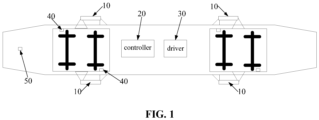
- FIG. 1 is a schematic structural view of a yaw damping system according to an embodiment of the present application.
- a railway vehicle is provided with a yaw damper 10. Due to the fact that the railway vehicle is running in different states, the parameter requirements for the yaw damper 10 are also different. In order to well adapt to the different operation states of railway vehicle, the yaw damper 10 provided in the embodiment is able to adjust its operation modes accordingly. Correspondingly, a yaw damping system is installed on the railway vehicle to switch operation modes of the yaw damper 10 according to operation parameters of the railway vehicle.
- the yaw damping system includes a yaw damper 10.
- the yaw damper 10 is installed on both a leading bogie and a trailing bogie of a vehicle body.
- the yaw damper 10 is connected between the vehicle body and the bogies.
- the yaw damper 10 is installed on both sides of the bogie.
- FIG. 1 exemplarily shows a structure in which four yaw dampers 10 are installed on the vehicle body.
- two yaw dampers 10 may also be installed on each side of the bogie, so that eight yaw dampers 10 are totally installed on one vehicle body.
- the specific configuration is set as required.
- the yaw damping system further includes a controller 20, which is communicated with the respective yaw damper 10 so as to control the operation mode of the yaw damper 10.
- the yaw damping system further includes an actuator 30, which is communicated with the controller 20.
- the controller 20 is used to generate actuating signals for the actuator 30 to control an action of the yaw damper 10 to switch the operation states.
- the controller 20 generates the actuating signals based on the operation information of the railway vehicle and the operation information of the yaw damper 10.
- the second detection module includes an acceleration sensor 40 and a gyroscope 50, as shown in FIG. 1 .
- Multiple acceleration sensors 40 are provided, and in the shown example, two acceleration sensors 40 are installed on each of the leading bogie and the trailing bogie of the vehicle body. The two acceleration sensors 40 on the same bogie are installed at diagonal positions. A yaw rate acceleration of the vehicle can be obtained through detection signals of the acceleration sensors 40.
- the gyroscope 50 is installed on the vehicle body to measure an angular velocity of the vehicle body.
- the controller 20 can calculate a truck curve radius of the vehicle based on the vehicle speed information, the measurement data of the gyroscope 50, and the measurement data of the acceleration sensor 40.
- the calculation formula is known in the art, which is not repeated here.
- the track curve radius may be obtained by various ways, and different information is required according to different calculation formulas. As such, corresponding detection elements may be provided to detect the corresponding vehicle operation parameters.
- the yaw damper 10 has three operation modes through a structural design (which is described in detail below): semi-active mode, low damping mode, and passive mode.
- a control method for the yaw damping system is further provided in the embodiment, which specifically includes: when the railway vehicle is running in a straight route, the controller 20 generates a first actuating signal and transmits it to the actuator 30, and the actuator 30 actuates the yaw damper 10 to be switched to the semi-active mode according to the received first actuating signal.
- the controller 20 When the railway vehicle is running in a straight route, the controller 20 generates a second actuating signal and transmits it to the actuator 30.
- the actuator 30 then actuates the yaw damper 10 based on the received second actuating signal to be switched to the low damping mode.
- the actuator 30 can control the yaw damper 10 to be switched to the passive mode to ensure the normal operation of the vehicle.
- the yaw damper 10 includes a hydraulic cylinder, which includes a cylinder body 11 and a piston 12.
- the piston 12 is slidably arranged inside the cylinder body 11 and divides an inner chamber of the cylinder body 11 into a rod chamber and a rodless chamber. Based on the orientation shown in the drawing, a left chamber of the cylinder body 11 is a rod chamber and a right chamber is a rodless chamber.
- a head of the piston 12 is further provided with a first check valve 13 that implements a unidirectional communication from the rodless chamber to the rod chamber.
- the yaw damper 10 is further provided with three branch oil lines, which are arranged in parallel and connected between the rod chamber and the rodless chamber outside the cylinder body 11.
- the three branch oil lines is referred to as a first branch oil line a1, a second branch oil line a2, and a third branch oil line a3.
- the second main oil line b2 is also connected to the oil reservoir 52 through a diverter oil line c1, and a third switch valve 61 is provided in the diverter oil line c1.
- the unloading valve 22 in the first branch oil line a1 is also connected with an orifice valve 23 in parallel.
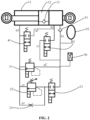
- FIG. 2 schematically shows the structure of the yaw damper 10 in the semi-active mode.
- the first switch valve 21, the second switch valve 41, and the third switch valve 61 are closed.
- the hydraulic oil flows out of the rod chamber of the cylinder body 11 and then flows into the rodless chamber of the cylinder body 11 through the third main oil line b3, the proportional electromagnetic valve 31 of the second branch oil line a2, and the second check valve 51 of the first main oil line b1.
- the oil reservoir 52 can replenish oil to the rodless chamber through the first main oil line b1.
- the damping force of the system is adjusted by the proportional electromagnetic valve 31.
- the second check valve 51 of the first main oil line b1 is in a closed state.
- the hydraulic oil in the rodless chamber flows to the rod chamber through the first check valve 13 and then flows into the oil reservoir 52 through the third main oil line b3 and the second branch oil line a2.
- the damping force of the system is adjusted by the proportional electromagnetic valve 31.
- the first detection module installed on the yaw damper 10 is embodied as a pressure sensor 70, which is used to obtain the oil pressure of the yaw damper 10.
- the controller 20 can calculate the current required damping force with a pre-stored algorithm based on the detection information of the pressure sensor 70 and the acceleration sensor 40, to control the proportional electromagnetic valve 31.
- the algorithm for obtaining the damping force is also known in the art, which are selected according to the actual needs. The specific algorithm will not be discussed in the present application.
- the yaw damper 10 When the railway vehicle is running in a straight route, the yaw damper 10 is in the semi-active mode, in which the parameters, such as the unloading force, the unloading speed and so on, can be adjusted in real time according to the different operation mileages, in order to extend the repair cycle and reduce operation costs.
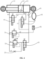
- the first switch valve 21 is closed and the second switch valve 41 and the third switch valve 61 are open.
- the hydraulic oil flows out of the rod chamber of the cylinder body 11 and then flows into the rodless chamber of the cylinder body 11 through the third main oil line b3, the second switch valve 41 of the third branch oil line a3, and the second main oil line b2.
- the oil reservoir 52 can replenish oil to the rodless chamber through the first main oil line b1, and the damping force of the yaw damper 10 is reduced to a minimum value.
- the second check valve 51 of the first main oil line b1 is in a closed state.
- the hydraulic oil in the rodless chamber flows to the rod chamber through the first check valve 13, and then flows into the rod chamber through the third main oil line b3, the third branch oil line a3, and the second main oil line b2. Excess oil can flow into the oil reservoir 52 through a diverter oil line c1.
- the yaw damper 10 When the railway vehicle is running in a curve route, the yaw damper 10 is in the low damping mode, in which a revolution stiffness of the vehicle may be reduced, the curve running speed of the vehicle may be increased and the wheel rail wear may be reduced.
- the first switch valve 21 is open and the second switch valve 41 and the third switch valve 61 are closed.
- the rod portion of the piston 12 of the hydraulic cylinder extends out in the direction shown in the drawing, that is, the piston 12 moves leftward, i.e., towards the rod chamber, the hydraulic oil flows out of the rod chamber of the cylinder body 11 and then flows into the rodless chamber through the third main oil line b3, the orifice valve 23 of the first branch oil line a1, and the first main oil line b1.
- the system can be switched to the passive mode to ensure the normal operation of the railway vehicle.
Landscapes
- Engineering & Computer Science (AREA)
- General Engineering & Computer Science (AREA)
- Mechanical Engineering (AREA)
- Physics & Mathematics (AREA)
- Fluid Mechanics (AREA)
- Vehicle Body Suspensions (AREA)
- Fluid-Damping Devices (AREA)
Applications Claiming Priority (2)
| Application Number | Priority Date | Filing Date | Title |
|---|---|---|---|
| CN202210411771.4A CN114738423B (zh) | 2022-04-19 | 2022-04-19 | 抗蛇行减振器、抗蛇行减振系统及其控制方法和轨道车辆 |
| PCT/CN2022/127817 WO2023202021A1 (fr) | 2022-04-19 | 2022-10-27 | Amortisseur de lacet, système d'amortisseur de lacet et procédé de commande associé, et véhicule ferroviaire |
Publications (2)
| Publication Number | Publication Date |
|---|---|
| EP4513052A1 true EP4513052A1 (fr) | 2025-02-26 |
| EP4513052A4 EP4513052A4 (fr) | 2025-09-24 |
Family
ID=82282178
Family Applications (1)
| Application Number | Title | Priority Date | Filing Date |
|---|---|---|---|
| EP22938243.7A Pending EP4513052A4 (fr) | 2022-04-19 | 2022-10-27 | Amortisseur de lacet, système d'amortisseur de lacet et procédé de commande associé, et véhicule ferroviaire |
Country Status (4)
| Country | Link |
|---|---|
| EP (1) | EP4513052A4 (fr) |
| JP (1) | JP7737570B2 (fr) |
| CN (1) | CN114738423B (fr) |
| WO (1) | WO2023202021A1 (fr) |
Families Citing this family (7)
| Publication number | Priority date | Publication date | Assignee | Title |
|---|---|---|---|---|
| CN114738423B (zh) * | 2022-04-19 | 2024-06-21 | 中车青岛四方机车车辆股份有限公司 | 抗蛇行减振器、抗蛇行减振系统及其控制方法和轨道车辆 |
| CN115929743B (zh) * | 2022-11-15 | 2025-08-01 | 北京精密机电控制设备研究所 | 一种多模式集成电静压伺服机构 |
| CN115892101B (zh) * | 2022-11-22 | 2025-06-06 | 杭州中车车辆有限公司 | 一种跨座式单轨车辆及其单轴转向架 |
| CN116573005A (zh) * | 2023-04-17 | 2023-08-11 | 湖南联诚轨道装备有限公司 | 一种轨道车辆转弯控制方法 |
| CN116398569A (zh) * | 2023-04-28 | 2023-07-07 | 中车株洲电力机车有限公司 | 一种电磁阀控式半主动减振器及其控制方法 |
| CN117450213A (zh) * | 2023-10-17 | 2024-01-26 | 西南交通大学 | 一种动态刚度可高低切换式抗蛇行减振器及其控制系统 |
| CN119004681B (zh) * | 2024-10-23 | 2024-12-24 | 成都大学 | 一种外置ads阀式阻尼可调抗蛇行减振器阻尼力的计算方法 |
Family Cites Families (17)
| Publication number | Priority date | Publication date | Assignee | Title |
|---|---|---|---|---|
| JP3437986B2 (ja) * | 1994-09-09 | 2003-08-18 | カヤバ工業株式会社 | セミアクティブ制御用ダンパおよび制御システム |
| JP3714699B2 (ja) * | 1995-03-31 | 2005-11-09 | カヤバ工業株式会社 | 減衰力可変ダンパ |
| JP3966937B2 (ja) * | 1997-02-28 | 2007-08-29 | カヤバ工業株式会社 | ダンパ装置 |
| JP4198308B2 (ja) * | 2000-08-14 | 2008-12-17 | カヤバ工業株式会社 | 制振用ダンパ及び制振システム |
| CN100364792C (zh) * | 2005-06-24 | 2008-01-30 | 浙江大学 | 车辆半主动悬挂用阻尼主动可调的液压减振器 |
| CN102069813B (zh) * | 2010-12-15 | 2012-06-06 | 青岛四方车辆研究所有限公司 | 开关式半主动悬挂系统 |
| GB2508524A (en) * | 2011-07-28 | 2014-06-04 | Hitachi Automotive Systems Ltd | Damper for railway vehicles |
| CN102537176B (zh) * | 2012-03-13 | 2014-07-02 | 株洲南车时代电气股份有限公司 | 一种阀控式半主动减振器 |
| JP6018675B2 (ja) * | 2015-08-24 | 2016-11-02 | Kyb株式会社 | 鉄道車両用制振装置 |
| JP6794244B2 (ja) * | 2016-12-21 | 2020-12-02 | 日本車輌製造株式会社 | 鉄道車両の制振装置 |
| CN110329297B (zh) * | 2019-06-19 | 2021-11-12 | 中车青岛四方机车车辆股份有限公司 | 一种抗蛇形减振系统、减振控制方法及车辆 |
| CN110360263B (zh) * | 2019-06-20 | 2021-08-27 | 中车青岛四方机车车辆股份有限公司 | 半主动抗蛇行减振器及减振系统、车辆 |
| CN110374950B (zh) * | 2019-06-20 | 2021-02-09 | 中车青岛四方机车车辆股份有限公司 | 减振器的油路控制方法及油路结构、减振器、车辆 |
| CN110360260B (zh) * | 2019-06-20 | 2021-08-31 | 中车青岛四方机车车辆股份有限公司 | 一种主动控制抗蛇形减振器及减振系统、车辆 |
| CN112648320B (zh) * | 2020-12-29 | 2025-06-10 | 南阳淅减汽车减振器有限公司 | 一种高频率响应阻尼可调半主动减振器 |
| CN214146396U (zh) * | 2020-12-31 | 2021-09-07 | 上海淅减汽车悬架有限公司 | 一种阻尼可调半主动减振器 |
| CN114738423B (zh) * | 2022-04-19 | 2024-06-21 | 中车青岛四方机车车辆股份有限公司 | 抗蛇行减振器、抗蛇行减振系统及其控制方法和轨道车辆 |
-
2022
- 2022-04-19 CN CN202210411771.4A patent/CN114738423B/zh active Active
- 2022-10-27 JP JP2024555959A patent/JP7737570B2/ja active Active
- 2022-10-27 WO PCT/CN2022/127817 patent/WO2023202021A1/fr not_active Ceased
- 2022-10-27 EP EP22938243.7A patent/EP4513052A4/fr active Pending
Also Published As
| Publication number | Publication date |
|---|---|
| CN114738423A (zh) | 2022-07-12 |
| JP2025511571A (ja) | 2025-04-16 |
| EP4513052A4 (fr) | 2025-09-24 |
| CN114738423B (zh) | 2024-06-21 |
| WO2023202021A1 (fr) | 2023-10-26 |
| JP7737570B2 (ja) | 2025-09-10 |
Similar Documents
| Publication | Publication Date | Title |
|---|---|---|
| EP4513052A1 (fr) | Amortisseur de lacet, système d'amortisseur de lacet et procédé de commande associé, et véhicule ferroviaire | |
| EP3988815B1 (fr) | Amortisseur de stabilisation semi-actif, système amortisseur et véhicule | |
| CN110360260B (zh) | 一种主动控制抗蛇形减振器及减振系统、车辆 | |
| US9193365B2 (en) | Railcar damping device | |
| CA2861550C (fr) | Dispositif de suppression des vibrations dans un vehicule ferroviaire | |
| CN110329297A (zh) | 一种抗蛇形减振系统、减振控制方法及车辆 | |
| RU2669909C1 (ru) | Устройство управления вибрацией железнодорожного вагона | |
| BR112012019735B1 (pt) | Sistema e método para monitoramento do nível de óleo em uma unidade de amortecimento em um veículo e meio legível por computador | |
| CN107107699A (zh) | 悬架装置和悬架控制装置 | |
| CN108349345A (zh) | 悬架装置 | |
| JP7025968B2 (ja) | 鉄道車両のホイールセットを制御するためのアクチュエータ | |
| FI92999B (fi) | Hydraulinen nostojärjestelmä | |
| CN117382364A (zh) | 一种车用空气悬架控制系统及控制方法 | |
| CN109501832A (zh) | 一种能实现转向架空重车压力调控的铁路货车制动系统 | |
| WO2023222823A1 (fr) | Bogie ferroviaire pour amortir un mouvement autour d'un axe de direction vertical et procédé d'amortissement de mouvement autour d'un axe de direction vertical du bogie ferroviaire | |
| JP2009040078A (ja) | 鉄道車両の車体傾斜制御システム | |
| CN115837823B (zh) | 一种改善车身俯仰角和车身侧倾角的油气悬挂系统及方法 | |
| CA2926329C (fr) | Methode de detection d'anomalie pour dispositif de controle d'inclinaison de chassis de vehicule | |
| JP5215610B2 (ja) | 鉄道車両の車体傾斜制御システム | |
| FI125345B (fi) | Kallistuksen ohjaus | |
| RU2794318C1 (ru) | Полуактивный демпфер колебаний, демпфирующая система и транспортное средство | |
| JP3996917B2 (ja) | 鉄道車両 | |
| CN121734467A (zh) | 一种轨道车辆主动减振系统及控制方法 | |
| KR200272066Y1 (ko) | 화차용 제동장치 | |
| WO2005053973A1 (fr) | Amortisseur dynamique semi-actif electro-hydraulique perfectionne pour vehicules de transport |
Legal Events
| Date | Code | Title | Description |
|---|---|---|---|
| STAA | Information on the status of an ep patent application or granted ep patent |
Free format text: STATUS: THE INTERNATIONAL PUBLICATION HAS BEEN MADE |
|
| PUAI | Public reference made under article 153(3) epc to a published international application that has entered the european phase |
Free format text: ORIGINAL CODE: 0009012 |
|
| STAA | Information on the status of an ep patent application or granted ep patent |
Free format text: STATUS: REQUEST FOR EXAMINATION WAS MADE |
|
| 17P | Request for examination filed |
Effective date: 20240916 |
|
| AK | Designated contracting states |
Kind code of ref document: A1 Designated state(s): AL AT BE BG CH CY CZ DE DK EE ES FI FR GB GR HR HU IE IS IT LI LT LU LV MC ME MK MT NL NO PL PT RO RS SE SI SK SM TR |
|
| DAV | Request for validation of the european patent (deleted) | ||
| DAX | Request for extension of the european patent (deleted) | ||
| A4 | Supplementary search report drawn up and despatched |
Effective date: 20250822 |
|
| RIC1 | Information provided on ipc code assigned before grant |
Ipc: F16F 9/19 20060101AFI20250818BHEP |