EP4513123A1 - Dispositif de transfert de chaleur tridimensionnel - Google Patents
Dispositif de transfert de chaleur tridimensionnel Download PDFInfo
- Publication number
- EP4513123A1 EP4513123A1 EP24195922.0A EP24195922A EP4513123A1 EP 4513123 A1 EP4513123 A1 EP 4513123A1 EP 24195922 A EP24195922 A EP 24195922A EP 4513123 A1 EP4513123 A1 EP 4513123A1
- Authority
- EP
- European Patent Office
- Prior art keywords
- thermally conductive
- hot area
- heat transfer
- transfer device
- protruding structure
- Prior art date
- Legal status (The legal status is an assumption and is not a legal conclusion. Google has not performed a legal analysis and makes no representation as to the accuracy of the status listed.)
- Pending
Links
Images


Classifications
-
- F—MECHANICAL ENGINEERING; LIGHTING; HEATING; WEAPONS; BLASTING
- F28—HEAT EXCHANGE IN GENERAL
- F28D—HEAT-EXCHANGE APPARATUS, NOT PROVIDED FOR IN ANOTHER SUBCLASS, IN WHICH THE HEAT-EXCHANGE MEDIA DO NOT COME INTO DIRECT CONTACT
- F28D15/00—Heat-exchange apparatus with the intermediate heat-transfer medium in closed tubes passing into or through the conduit walls ; Heat-exchange apparatus employing intermediate heat-transfer medium or bodies
- F28D15/02—Heat-exchange apparatus with the intermediate heat-transfer medium in closed tubes passing into or through the conduit walls ; Heat-exchange apparatus employing intermediate heat-transfer medium or bodies in which the medium condenses and evaporates, e.g. heat pipes
- F28D15/0275—Arrangements for coupling heat-pipes together or with other structures, e.g. with base blocks; Heat pipe cores
-
- F—MECHANICAL ENGINEERING; LIGHTING; HEATING; WEAPONS; BLASTING
- F28—HEAT EXCHANGE IN GENERAL
- F28D—HEAT-EXCHANGE APPARATUS, NOT PROVIDED FOR IN ANOTHER SUBCLASS, IN WHICH THE HEAT-EXCHANGE MEDIA DO NOT COME INTO DIRECT CONTACT
- F28D15/00—Heat-exchange apparatus with the intermediate heat-transfer medium in closed tubes passing into or through the conduit walls ; Heat-exchange apparatus employing intermediate heat-transfer medium or bodies
- F28D15/02—Heat-exchange apparatus with the intermediate heat-transfer medium in closed tubes passing into or through the conduit walls ; Heat-exchange apparatus employing intermediate heat-transfer medium or bodies in which the medium condenses and evaporates, e.g. heat pipes
- F28D15/0233—Heat-exchange apparatus with the intermediate heat-transfer medium in closed tubes passing into or through the conduit walls ; Heat-exchange apparatus employing intermediate heat-transfer medium or bodies in which the medium condenses and evaporates, e.g. heat pipes the conduits having a particular shape, e.g. non-circular cross-section, annular
-
- F—MECHANICAL ENGINEERING; LIGHTING; HEATING; WEAPONS; BLASTING
- F28—HEAT EXCHANGE IN GENERAL
- F28D—HEAT-EXCHANGE APPARATUS, NOT PROVIDED FOR IN ANOTHER SUBCLASS, IN WHICH THE HEAT-EXCHANGE MEDIA DO NOT COME INTO DIRECT CONTACT
- F28D15/00—Heat-exchange apparatus with the intermediate heat-transfer medium in closed tubes passing into or through the conduit walls ; Heat-exchange apparatus employing intermediate heat-transfer medium or bodies
- F28D15/02—Heat-exchange apparatus with the intermediate heat-transfer medium in closed tubes passing into or through the conduit walls ; Heat-exchange apparatus employing intermediate heat-transfer medium or bodies in which the medium condenses and evaporates, e.g. heat pipes
- F28D15/04—Heat-exchange apparatus with the intermediate heat-transfer medium in closed tubes passing into or through the conduit walls ; Heat-exchange apparatus employing intermediate heat-transfer medium or bodies in which the medium condenses and evaporates, e.g. heat pipes with tubes having a capillary structure
- F28D15/046—Heat-exchange apparatus with the intermediate heat-transfer medium in closed tubes passing into or through the conduit walls ; Heat-exchange apparatus employing intermediate heat-transfer medium or bodies in which the medium condenses and evaporates, e.g. heat pipes with tubes having a capillary structure characterised by the material or the construction of the capillary structure
-
- F—MECHANICAL ENGINEERING; LIGHTING; HEATING; WEAPONS; BLASTING
- F28—HEAT EXCHANGE IN GENERAL
- F28D—HEAT-EXCHANGE APPARATUS, NOT PROVIDED FOR IN ANOTHER SUBCLASS, IN WHICH THE HEAT-EXCHANGE MEDIA DO NOT COME INTO DIRECT CONTACT
- F28D15/00—Heat-exchange apparatus with the intermediate heat-transfer medium in closed tubes passing into or through the conduit walls ; Heat-exchange apparatus employing intermediate heat-transfer medium or bodies
- F28D15/02—Heat-exchange apparatus with the intermediate heat-transfer medium in closed tubes passing into or through the conduit walls ; Heat-exchange apparatus employing intermediate heat-transfer medium or bodies in which the medium condenses and evaporates, e.g. heat pipes
- F28D15/04—Heat-exchange apparatus with the intermediate heat-transfer medium in closed tubes passing into or through the conduit walls ; Heat-exchange apparatus employing intermediate heat-transfer medium or bodies in which the medium condenses and evaporates, e.g. heat pipes with tubes having a capillary structure
- F28D15/043—Heat-exchange apparatus with the intermediate heat-transfer medium in closed tubes passing into or through the conduit walls ; Heat-exchange apparatus employing intermediate heat-transfer medium or bodies in which the medium condenses and evaporates, e.g. heat pipes with tubes having a capillary structure forming loops, e.g. capillary pumped loops
Definitions
- the present disclosure is related to the field of heat transfer devices, in particular a three-dimensional heat transfer device.
- a heat transfer device includes a heat transfer plate, a heat pipe, and a heat dissipater (e.g., fins and fan) to dissipate heat generated by a heat source.
- the heat transfer plate contacts the heat source to absorb heat
- the heat pipe is disposed between the heat transfer plate and the heat dissipater to transfer the heat to the heat dissipater to dissipate the heat via the heat dissipater.
- capillary structures in both the heat transfer plate and the heat pipe are proximate with each other but not connected, which causes the heat transfer plate and the heat pipe to work independently because the capillary structures have a larger attraction force to the working fluid than gravity. Consequently, this situation reduces the flow of the working fluid, causing a decrease in the heat dissipation efficiency of the heat transfer device.
- manufacturers seek to improve the heat dissipation efficiency of three-dimensional heat transfer devices by either increasing the capillary force of the structures or enhancing the thermal conductivity of the evaporation zone.
- current devices still face challenges with the efficient return of vaporized working fluid, leading to overall heat dissipation performance that does not meet user expectations. Therefore, improving the return efficiency of the vaporized working fluid to improve the heat dissipation efficiency of three-dimensional heat transfer devices remains a critical challenge for researchers.
- the three-dimensional heat transfer device can include a first thermal conductive shell, a second thermal conductive shell that connects with the first thermally conductive shell to form a liquid-tight chamber. Further, at least one thermally conductive assembly of hot area arranged in the liquid-tight chamber and disposed on the second thermally conductive shell, the at least one thermally conductive assembly of hot area includes a plurality of extended thermally conductive structures of hot area, and at least one thermally conductive assembly of cold area arranged adjacent to the at least one thermally conductive assembly of hot area, the at least one thermally conductive assembly of cold area includes at least two extended thermally conductive structures of cold area that are separated to form a pressure drop notch therebetween.
- a plurality of heat pipes are preferably disposed on or preferably connected with the first thermally conductive shell and are in fluid communication with the liquid-tight chamber.
- the second thermally conductive shell can include a base plate, a first protruding structure, a second protruding structure, the first protruding structure protrudes from the base plate and away from the first thermally conductive shell, the second protruding structure protrudes from the first protruding structure and away from the first thermally conductive shell, the second protruding structure having an inner surface facing the first thermally conductive shell, and the at least one thermally conductive assembly of hot area and the at least one thermally conductive assembly of cold area protruding from the inner surface of the second protruding structure.
- the three-dimensional heat transfer device can further include a plurality of supporting structures of hot area and a plurality of supporting structures of cold area, wherein the plurality of supporting structures of hot area protrude from the plurality of extended thermally conductive structures of hot area, the plurality of supporting structures of cold area protrude from the plurality of extended thermally conductive structures of cold area, and the plurality of supporting structures of hot area having lengths greater than the plurality of supporting structures of cold area.
- the three-dimensional heat transfer device can further include a first capillary structure in contact with the first thermally conductive shell.
- the three-dimensional heat transfer device can further include a second capillary structure in contact with the first thermally conductive shell, the at least one thermally conductive assembly of hot area, the at least one thermally conductive assembly of cold area, the plurality of supporting structures of hot area, and the plurality of supporting structures of cold area.
- the plurality of extended thermally conductive structures of hot area and the second capillary structure are integrated into a single structure.
- the plurality of extended thermally conductive structures of hot area are powder-sintered structures, which are independent structures that are different from the second protruding structure.
- the second capillary structure and the extended thermally conductive structures of hot area can have different perforated capillary with pores.
- the second protruding structure can include a bottom side, a top side, a left side and a right side, the bottom side is opposite to the top side, the left side is opposite to the right side, and the at least one thermally conductive assembly of hot area is adjacent to the top side and the right side of the second protruding structure.
- the second protruding structure can include a bottom side, a top side, a left side and a right side, the bottom side is opposite to the top side, the left side is opposite to the right side, and the at least one thermally conductive assembly of hot area is adjacent to the bottom side and the left side of the second protruding structure.
- the second protruding structure can include a bottom side, a top side, a left side and a right side, the bottom side is opposite to the top side, the left side is opposite to the right side, and the at least one thermally conductive assembly of hot area is adjacent to the top side and the left side of the second protruding structure.
- the second protruding structure can include a bottom side, a top side, a left side and a right side, the bottom side is opposite to the top side, the left side is opposite to the right side, and the at least one thermally conductive assembly of hot area is adjacent to the bottom side and the right side of the second protruding structure.
- the second protruding structure can include a bottom side, a top side, a left side and a right side, the bottom side is opposite to the top side, the left side is opposite to the right side, and the at least one thermally conductive assembly of hot area is separated from the top side, the bottom side, the left side, and the right side of the second protruding structure.
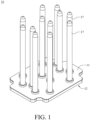
- Figs. 1-4 illustrate various views of a three-dimensional heat transfer device 10 according to an embodiment of the present disclosure.
- Fig. 1 illustrates a perspective view of the three-dimensional heat transfer device 10.
- Fig. 2 illustrates a perspective view of a second thermally conductive shell 12 of the three-dimensional heat transfer device 10.
- Fig. 3 illustrates a section view of the three-dimensional heat transfer device 10.
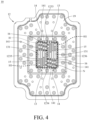
- Fig. 4 illustrates a plan view of the second thermally conductive shell 12 of the three-dimensional heat transfer device 10.
- the three-dimensional heat transfer device 10 includes a first thermally conductive shell 11, a second thermally conductive shell 12, two thermally conductive assemblies of a hot area 13, two thermally conductive assemblies of a cold area 14, multiple supporting structures of hot area 15, multiple supporting structures of hot area 16, multiple heat pipes 17, a first capillary structure 18, and a first capillary structure 19.
- the second thermal conductive shell 12 is connected with the first thermal conductive shell 11 to form a liquid-tight chamber S.
- the liquid-tight chamber S can be filled with a cooling fluid (not shown), e.g., water or refrigerant.
- the second thermal conductive shell 12 includes a base plate 121, a first protruding structure 122, and a second protruding structure 123.
- the first protruding structure 122 protrudes from the base plate 121 and away from the first thermally conductive shell 11.
- the second protruding structure 123 protrudes from the first protruding structure 122 and away from the first thermally conductive shell 11.
- the second protruding structure 123 includes an inner surface 1231, a heat exchange surface 1232, a bottom side 1233, a top side 1234, a left side 1235, and a right side 1236.
- the inner surface 1231 faces the first thermally conductive shell 11.
- the heat exchange surface 1232 is on the opposite side of the inner surface 1231 and is used for thermally coupling with a heat source H, so that the cooling fluid located in the liquid-tight chamber S can absorb the heat that the heat source H transmits to the thermal conductive protruding structures (e.g., 122 and 123) through the heat exchange surface 1232.
- Thermal coupling can be achieved by thermal contact or connection through other thermally conductive media between the heat exchange surface 1232 and the heat source H.
- the heat source H can be anything that dissipates heat, for example, a GPU, a CPU, or any other electronic devices or components.
- the bottom 1233 is opposite to the top 1234, and the left 1235 is opposite to the right 1236.
- the bottom side 1233, the top side 1234, the left side 1235 and the right side 1236 jointly surround the inner surface 1231 and the heat exchange surface 1232.
- the two thermally conductive assemblies of hot area 13 and the two thermally conductive assemblies of cold area 14 are located in the liquid-tight chamber S and protrude from the inner surface 1231 of the second protruding structure 123.
- One of the thermally conductive assemblies of hot area 13 is adj acent to the top side 1234 and the right side 1236 of the second protruding structure 123.
- the other of the thermally conductive assemblies of hot area 13 is adjacent to the bottom side 1233 and the left side 1235 of the second protruding structure 123. That is, the two thermally conductive assemblies of hot area 13 are arranged along a diagonal of the second protruding structure 123.
- Each of the two thermally conductive assemblies of cold area 14 is placed side by side on one side of the thermally conductive assemblies of hot area 13.
- Each of the two thermally conductive assemblies of hot area 13 corresponds to one of the hot spots H1 of the heat source H respectively. It should be noted that, relative to the hot area referred to in the thermally conductive assemblies of hot area 13, the cold area referred to in the thermally conductive assemblies of cold area 14 is the area where the temperature in the corresponding heat source is lower than the hot spot H1.
- Each thermally conductive assembly of hot area 13 includes strips of extended thermally conductive structures of hot area 131.
- Each strip of the extended thermally conductive structures of hot area 131 is arranged side by side to each other.
- each thermally conductive assembly of hot area 13 includes four parallel strips of extended thermally conductive structures of hot area 131.
- each strip of extended thermally conductive structures of hot area are arranged parallel to each other, but the embodiment is not limited thereto.
- each strip of extended thermally conductive structures can be arranged convergent or divergent to each other.
- Each thermally conductive assembly of cold area 14 includes strips of extended thermally conductive structures of cold area 141.
- Each strip of the extended thermally conductive structures of cold area 141 includes multiple extended thermally conductive structures of cold area 141 that are separated from each other by a pressure drop notch N.
- Each strip of the extended thermally conductive structures of cold area 141 is arranged side by side to each other.
- the thermally conductive assembly of cold area 14 at the bottom right of the second protruding structure 123 includes four parallel strips of extended thermally conductive structures of cold area 141, and each strip includes two extended thermally conductive structures of cold area 141 that are separated by pressure drop notches N.
- each strip of extended thermally conductive structures of hot area are arranged parallel to each other, but the embodiment is not limited thereto.
- each strip of extended thermally conductive structures can be arranged convergent or divergent to each other.
- a gap is left between the extended thermally conductive structures of hot area 131 and the first thermally conductive shell 11. That is, the top side of the extended thermally conductive structures of hot area 131 has space for the cooling fluid to flow through.
- these structures reduce vapor pressure and the high liquid pressure drop caused by the capillary action of the powder-sintered capillary structure. Therefore, the extended thermally conductive structures of hot area 131 and extended thermally conductive structures of cold area 141 can improve the heat dissipation efficiency of the three-dimensional heat transfer device 10.
- the supporting structures of hot area 15 protrude from the extended thermally conductive structures of hot area 131 and contact the first thermally conductive shell 11.
- the supporting structures of cold area 16 protrude from the extended thermally conductive structures of cold area 141 and contact the first thermally conductive shell 11.
- heat pipes 17 are disposed in the first thermally conductive shell 11 and are connected with the liquid-tight chamber S.
- the heat pipes 17 described herein do not include any capillary structures on the inner surface.
- the heat pipes 17 can include capillary structures on the inner surface according to the specific design or the desired application of the three-dimensional heat transfer device 10.
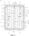
- Fig. 5 illustrates a top view of the second protruding structure 123 of the three-dimensional heat transfer device 10.
- Each supporting structure of hot area 15 has a length of L1 and each supporting structure of cold area 16 has a length of L2.
- the length L1 is greater than the length L2.
- the length of L1 can also be less than or equal to the length of L2 to suit the specific needs of the three-dimensional heat exchange device 10.
- the cooling fluid absorbs the heat from the heat source H and vaporizes.
- the vaporized cooling fluid may flow along the direction A1 between the extended thermally conductive structures of hot area 131, flows along the direction A2 through the space on the top side of the extended thermally conductive structures of hot area 131, and flows through the pressure drop notches N. Eventually, and the vaporized cooling fluid flows into the heat pipes 17 to dissipate heat.
- a first capillary structure 18 can be arranged on the inner surface of the first thermally conductive shell 11.
- the first capillary structure 18 is arranged on almost all surface areas of the first thermally conductive shell 11 facing the liquid-tight chamber S.
- a second capillary structure 19 can be arranged on the surfaces of the second thermally conductive shell 12, the thermally conductive assemblies of hot area 13, the thermally conductive assemblies of cold area 14, the supporting structures of hot area 15, and the supporting structures of hot area 16.
- the second capillary structure 19 is arranged on almost all surface areas of the second thermally conductive shell 12, the thermally conductive assemblies of hot area 13, the thermally conductive assemblies of cold area 14, the supporting structures of hot area 15, and the supporting structures of hot area 16 facing the liquid-tight chamber S.
- the cooling fluid can absorb the heat of the heat source H and the vaporized cooling fluid reflux through the first capillary structure 18 and the second capillary structure 19 after vaporization.
- the portions of the second capillary structure 19 that are arranged on the surfaces of the extended thermally conductive structure of hot area 131 can be used to transfer heat from the hot spot H1.
- the portions of the second capillary structure 19 that are arranged on the surfaces of the extended thermally conductive structures of cold area 141 forming the gaps as the pressure drop notches N can provide vapor pressure reduction to the vaporized cooling fluid when flow through the pressure drop notches N.
- the extended thermally conductive structures of hot area 131 and the second capillary structure 19 can be integrated into a single capillary structure.
- the extended thermally conductive structures of hot area 131 are powder-sintered structures, which are independent structures that are different from the second protruding structure 123. Additionally, the second capillary structure 19 and the extended thermally conductive structures of hot area 131 can have different perforated capillary with pores.
- the supporting structures of cold area 16 can be quadrangular columnar, while the second capillary structure 19 arranged on the surfaces of the supporting structures of cold area 16 can be cylindrical.
- the shape of the supporting structures of cold area 16 and the shape of the second capillary structure 19 arranged in the supporting structures of cold area 16 can be different.
- the shape of the supporting structures of cold area 16 and the shape of the second capillary structures 19 can also be any suitable or be the same.
- the vaporized cooling fluid after absorbing the heat from the heat source H flows through the space above the top side of the extended thermally conductive structures of hot area 131 and the pressure drop notches N as gaps between extended thermally conductive structures of cold area 141. It should be noted that, at least a portion of the vaporized cooling fluid may simultaneously flow in different directions within the evaporation zone in the cooling cycle, dispersing into any available space before entering the pressure drop notches N. This way, the flow path of vaporized cooling fluid is dispersed which further reduces the vapor pressure, which results in the improvement of the heat dissipation efficiency of the three-dimensional heat exchange device 10.
- the pressure loss between the thermally conductive assemblies of hot area 13 and the thermally conductive assemblies of cold area 14 can cause a temperature difference and form thermal resistance.
- the pressure drop notches N can reduce the pressure loss, which reduces the thermal resistance and further improves the heat dissipation efficiency of the three-dimensional heat exchange device 10.
- the three-dimensional heat transfer device 10 is arranged upright according to the position of the heat source. That is, the second protruding structure 123 of the three-dimensional heat transfer device 10 has a bottom side 1233, a top side 1234, a left side 1235, and a right side 1236. In some embodiments, the three-dimensional heat transfer device 10 may also be arranged to lie flat according to the position of the heat source. That is, the second protruding structure 123 of the three-dimensional heat transfer device 10 may have a front side, a rear side, a left side, and a right side.
- the second capillary structure 19 arranged on the surface of the second thermally conductive shell 12, the surfaces of the thermally conductive assemblies of hot area 13, the surfaces of the thermally conductive assemblies of cold area 14, the surfaces of the supporting structures of hot area 15, and the surfaces of the supporting structures of cold area 16 can be constituted of the same material or different materials.
- the three-dimensional heat transfer device 10 discussed above includes two thermally conductive assemblies of hot area 13 which correspond to two hot spots of the heat source H. Other examples of the arrangement of the thermally conductive assemblies of hot area are illustrated in Figs. 6-10 .
- Fig. 6 illustrates a plan view of the second protruding structure of a three-dimensional heat transfer device 10A according to an embodiment of the present disclosure.
- the three-dimensional heat transfer device 10A is similar to the three-dimensional heat transfer device 10.
- the three-dimensional heat transfer device 10A only includes one thermally conductive assembly of hot area 13A.
- the thermally conductive assembly of hot area 13A corresponds to one of the hot spots H1 of the heat source H.
- the thermally conductive assembly of hot area 13A is arranged adjacent to the top side 1234 and the right side 1236 of the second protruding structure 123. That is, the thermally conductive assembly of hot area 13A is located in the upper right corner of the second protruding structure 123.
- the cooling fluid absorbs the heat of the heat source and vaporizes, and the vaporized cooling fluid flows along the direction B1 between the extended thermally conductive structures of hot area 131 and along the direction B2 through the space above the top side of the extended thermally conductive structures of hot area 131 and the pressure drop notches N to reduce the vapor pressure.
- the vaporized cooling fluid may simultaneously flow in different directions within the evaporation zone in the cooling cycle, dispersing into any available space before entering the pressure drop notches N.
- Fig. 7 illustrates a plan view of the second protruding structure of a three-dimensional heat transfer device 10B according to an embodiment of the present disclosure.
- the three-dimensional heat transfer device 10B is similar to the three-dimensional heat transfer device 10, so the differences will be described, and the similarities will not be repeated.
- the three-dimensional heat transfer device 10B includes one thermally conductive assembly of hot area 13B.
- the thermally conductive assembly of hot area 13B corresponds to one of the hot spots H1 of the heat source H.
- the thermally conductive assembly of hot area 13B is arranged adjacent to the bottom side 1233 and the left side 1235 of the second protruding structure 123. That is, the thermally conductive assembly of hot area 13B is located in the bottom left corner of the second protruding structure 123.
- the cooling fluid absorbs the heat of the heat source and vaporizes, and the vaporized cooling fluid flows along the direction C1 between the extended thermally conductive structures of hot area 131 and along the direction C2 through the space above the top side of the extended thermally conductive structures of hot area 131 and the pressure drop notches N to reduce the vapor pressure.
- the vaporized cooling fluid may simultaneously flow in different directions within the evaporation zone in the cooling cycle, dispersing into any available space before entering the pressure drop notches N.
- Fig. 8 illustrates a plan view of the second protruding structure of a three-dimensional heat transfer device 10C according to an embodiment of the present disclosure.
- the three-dimensional heat transfer device 10C is similar to the three-dimensional heat transfer device 10, so the differences will be described, and the similarities will not be repeated.
- the three-dimensional heat transfer device 10C only includes one thermally conductive assembly of hot area 13C.
- the thermally conductive assembly of hot area 13C corresponds to one of the hot spots H1 of the heat source H.
- the thermally conductive assembly of hot area 13C is arranged adjacent to the top side 1234 and the left side 1235 of the second protruding structure 123.
- the thermally conductive assembly of hot area 13C is located in the top left corner of the second protruding structure 123.
- the cooling fluid absorbs the heat of the heat source and vaporizes, and the vaporized cooling fluid flows along the direction D1 between the extended thermally conductive structures of hot area 131 and along the direction D2 through the space above the top side of the extended thermally conductive structures of hot area 131 and the pressure drop notches N to reduce the vapor pressure.
- at least a portion of the vaporized cooling fluid may simultaneously flow in different directions within the evaporation zone in the cooling cycle, dispersing into any available space before entering the pressure drop notches N.
- Fig. 9 illustrates a plan view of the second protruding structure of a three-dimensional heat transfer device 10D according to an embodiment of the present disclosure.
- the three-dimensional heat transfer device 10D is similar to the three-dimensional heat transfer device 10, so the differences will be described, and the similarities will not be repeated.
- the three-dimensional heat transfer device 10D only includes one thermally conductive assembly of hot area 13D.
- the thermally conductive assembly of hot area 13D corresponds to one of the hot spots H1 of the heat source H.
- the thermally conductive assembly of hot area 13D is arranged adjacent to the bottom side 1233 and the right side 1236 of the second protruding structure 123.
- the thermally conductive assembly of hot area 13D is located in the bottom right corner of the second protruding structure 123.
- the cooling fluid absorbs the heat of the heat source and vaporizes, and the vaporized cooling fluid flows along the direction E1 between the extended thermally conductive structures of hot area 131and along the direction E2 through the space above the top side of the extended thermally conductive structures of hot area 131 and the pressure drop notches N to reduce the vapor pressure.
- at least a portion of the vaporized cooling fluid may simultaneously flow in different directions within the evaporation zone in the cooling cycle, dispersing into any available space before entering the pressure drop notches N.
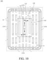
- Fig. 10 illustrates a plan view of the second protruding structure of a three-dimensional heat transfer device 10E according to embodiments of the present disclosure.
- the three-dimensional heat transfer device 10E is similar to the three-dimensional heat transfer device 10, so the differences will be described, and the similarities will not be repeated.
- the three-dimensional heat transfer device 10E only includes one thermally conductive assembly of hot area 13E.
- the thermally conductive assembly of hot area 13 corresponds to one of the hot spots H1 of the heat source H.
- the thermally conductive assembly of hot area 13E is arranged away from the bottom side 1233, the top side 1234, the left side 1235, and the right side 1236 of the second protruding structure 123.
- the thermally conductive assembly of hot area 13E is located in the center of the second protruding structure 123.
- the cooling fluid absorbs the heat of the heat source and vaporizes, and the vaporized cooling fluid flows along the direction F1 between the extended thermally conductive structures of hot area 131 and along the direction F2 through the space above the top side of the extended thermally conductive structures of hot area 131 and the pressure drop notches N to reduce the vapor pressure.
- at least a portion of the vaporized cooling fluid may simultaneously flow in different directions within the evaporation zone in the cooling cycle, dispersing into any available space before entering the pressure drop notches N.
- compositions and methods are described in terms of “comprising,” “containing,” or “including” various components or steps, the compositions and methods can also “consist essentially of” or “consist of” the various components and steps. All numbers and ranges disclosed above may vary by some number. Whenever a numerical range with a lower limit and an upper limit is disclosed, any number and any included range falling within the range is specifically disclosed.
Landscapes
- Engineering & Computer Science (AREA)
- Life Sciences & Earth Sciences (AREA)
- Sustainable Development (AREA)
- Physics & Mathematics (AREA)
- Thermal Sciences (AREA)
- Mechanical Engineering (AREA)
- General Engineering & Computer Science (AREA)
- Cooling Or The Like Of Electrical Apparatus (AREA)
- Heat-Exchange Devices With Radiators And Conduit Assemblies (AREA)
- General Details Of Gearings (AREA)
Applications Claiming Priority (1)
| Application Number | Priority Date | Filing Date | Title |
|---|---|---|---|
| TW112131505A TWI842615B (zh) | 2023-08-22 | 2023-08-22 | 立體傳熱裝置 |
Publications (1)
| Publication Number | Publication Date |
|---|---|
| EP4513123A1 true EP4513123A1 (fr) | 2025-02-26 |
Family
ID=92077082
Family Applications (1)
| Application Number | Title | Priority Date | Filing Date |
|---|---|---|---|
| EP24195922.0A Pending EP4513123A1 (fr) | 2023-08-22 | 2024-08-22 | Dispositif de transfert de chaleur tridimensionnel |
Country Status (4)
| Country | Link |
|---|---|
| US (1) | US20250067519A1 (fr) |
| EP (1) | EP4513123A1 (fr) |
| CN (3) | CN221593607U (fr) |
| TW (1) | TWI842615B (fr) |
Families Citing this family (1)
| Publication number | Priority date | Publication date | Assignee | Title |
|---|---|---|---|---|
| US20260071826A1 (en) * | 2024-09-11 | 2026-03-12 | Nidec Chaun-Choung Technology Corporation | Three-dimensional loop-type heat exchanging device |
Citations (4)
| Publication number | Priority date | Publication date | Assignee | Title |
|---|---|---|---|---|
| US20220163267A1 (en) * | 2020-11-24 | 2022-05-26 | Vast Glory Electronics & Hardware & Plastic(Hui Zhou) Ltd. | Three-dimensional heat exchanger |
| US20230184491A1 (en) * | 2021-12-15 | 2023-06-15 | Vast Glory Electronics & Hardware & Plastic(Hui Zhou) Ltd. | Three-dimensional heat transfer device |
| US20230204300A1 (en) * | 2019-05-10 | 2023-06-29 | Cooler Master Co., Ltd. | Vapor chamber and manufacturing method of the same |
| US20230213288A1 (en) * | 2022-01-06 | 2023-07-06 | Vast Glory Electronics & Hardware & Plastic(Hui Zhou) Ltd. | Three-dimensional heat transfer device |
Family Cites Families (1)
| Publication number | Priority date | Publication date | Assignee | Title |
|---|---|---|---|---|
| TWI769077B (zh) * | 2021-09-09 | 2022-06-21 | 英業達股份有限公司 | 散熱器組件 |
-
2023
- 2023-08-22 TW TW112131505A patent/TWI842615B/zh active
- 2023-12-28 CN CN202323603547.4U patent/CN221593607U/zh active Active
- 2023-12-28 CN CN202311831180.3A patent/CN119509224A/zh active Pending
- 2023-12-28 CN CN202323603522.4U patent/CN221593606U/zh active Active
-
2024
- 2024-08-19 US US18/808,742 patent/US20250067519A1/en active Pending
- 2024-08-22 EP EP24195922.0A patent/EP4513123A1/fr active Pending
Patent Citations (4)
| Publication number | Priority date | Publication date | Assignee | Title |
|---|---|---|---|---|
| US20230204300A1 (en) * | 2019-05-10 | 2023-06-29 | Cooler Master Co., Ltd. | Vapor chamber and manufacturing method of the same |
| US20220163267A1 (en) * | 2020-11-24 | 2022-05-26 | Vast Glory Electronics & Hardware & Plastic(Hui Zhou) Ltd. | Three-dimensional heat exchanger |
| US20230184491A1 (en) * | 2021-12-15 | 2023-06-15 | Vast Glory Electronics & Hardware & Plastic(Hui Zhou) Ltd. | Three-dimensional heat transfer device |
| US20230213288A1 (en) * | 2022-01-06 | 2023-07-06 | Vast Glory Electronics & Hardware & Plastic(Hui Zhou) Ltd. | Three-dimensional heat transfer device |
Also Published As
| Publication number | Publication date |
|---|---|
| CN221593606U (zh) | 2024-08-23 |
| CN221593607U (zh) | 2024-08-23 |
| TW202509411A (zh) | 2025-03-01 |
| TWI842615B (zh) | 2024-05-11 |
| CN119509224A (zh) | 2025-02-25 |
| US20250067519A1 (en) | 2025-02-27 |
Similar Documents
| Publication | Publication Date | Title |
|---|---|---|
| CN101040162B (zh) | 带有具有沸腾增强作用的多重毛细结构的蒸汽室 | |
| CN100390488C (zh) | 热传递装置及其制造方法 | |
| US11754345B2 (en) | Heat dissipation device | |
| CN113437034A (zh) | 均温板及电子设备 | |
| JP2005518518A (ja) | 毛管蒸発器 | |
| EP4513123A1 (fr) | Dispositif de transfert de chaleur tridimensionnel | |
| WO2009072703A1 (fr) | Microdispositif caloporteur de type plaque plate | |
| TWI888109B (zh) | 立體均溫板散熱裝置 | |
| CN220188941U (zh) | 一种用于cpu的三维散热器 | |
| EP4579166A1 (fr) | Dispositif de transmission de chaleur tridimensionnel | |
| EP4600597A1 (fr) | Dispositif de refroidissement à haute chaleur | |
| KR100451916B1 (ko) | 박판형 히트파이프 구조의 냉각장치 | |
| CN100557368C (zh) | 热管散热器 | |
| JP2000156447A (ja) | 沸騰冷却装置 | |
| TWI907251B (zh) | 散熱組件 | |
| TWI885552B (zh) | 立體均溫板裝置 | |
| CN114698328B (zh) | 流体冷却式散热模块 | |
| TWI889409B (zh) | 均溫板裝置 | |
| JPH10267573A (ja) | 平面型ヒートパイプ | |
| US20250254829A1 (en) | Vapor chamber | |
| KR20260012603A (ko) | 흡열 구조 및 이를 구비한 방열장치 | |
| CN223243404U (zh) | 散热器 | |
| US20260006748A1 (en) | Air-cooled heat sink | |
| TWM673318U (zh) | 具有冷卻區之真空腔均熱板結構 | |
| US20260113885A1 (en) | Heat dissipation assembly |
Legal Events
| Date | Code | Title | Description |
|---|---|---|---|
| PUAI | Public reference made under article 153(3) epc to a published international application that has entered the european phase |
Free format text: ORIGINAL CODE: 0009012 |
|
| STAA | Information on the status of an ep patent application or granted ep patent |
Free format text: STATUS: THE APPLICATION HAS BEEN PUBLISHED |
|
| AK | Designated contracting states |
Kind code of ref document: A1 Designated state(s): AL AT BE BG CH CY CZ DE DK EE ES FI FR GB GR HR HU IE IS IT LI LT LU LV MC ME MK MT NL NO PL PT RO RS SE SI SK SM TR |
|
| STAA | Information on the status of an ep patent application or granted ep patent |
Free format text: STATUS: REQUEST FOR EXAMINATION WAS MADE |
|
| 17P | Request for examination filed |
Effective date: 20250825 |