EP4513149A1 - Verbrauchszähler mit druckübergangserkennung - Google Patents
Verbrauchszähler mit druckübergangserkennung Download PDFInfo
- Publication number
- EP4513149A1 EP4513149A1 EP23192892.0A EP23192892A EP4513149A1 EP 4513149 A1 EP4513149 A1 EP 4513149A1 EP 23192892 A EP23192892 A EP 23192892A EP 4513149 A1 EP4513149 A1 EP 4513149A1
- Authority
- EP
- European Patent Office
- Prior art keywords
- measurement circuit
- flow rate
- pressure transient
- utility
- utility meter
- Prior art date
- Legal status (The legal status is an assumption and is not a legal conclusion. Google has not performed a legal analysis and makes no representation as to the accuracy of the status listed.)
- Withdrawn
Links
Images


Classifications
-
- G—PHYSICS
- G01—MEASURING; TESTING
- G01F—MEASURING VOLUME, VOLUME FLOW, MASS FLOW OR LIQUID LEVEL; METERING BY VOLUME
- G01F1/00—Measuring the volume flow or mass flow of fluid or fluent solid material wherein the fluid passes through a meter in a continuous flow
- G01F1/66—Measuring the volume flow or mass flow of fluid or fluent solid material wherein the fluid passes through a meter in a continuous flow by measuring frequency, phase shift or propagation time of electromagnetic or other waves, e.g. using ultrasonic flowmeters
- G01F1/667—Arrangements of transducers for ultrasonic flowmeters; Circuits for operating ultrasonic flowmeters
Definitions
- the present invention relates to the technical field of utility meters for measuring an amount of a liquid delivered to a consumer, more specifically to the field of utility meters with ultrasonic flow measurement.
- Pressure transients in utility distribution networks are unwanted incidents that can damage pipe infrastructure and lead to pipe failures. Effective detection of pressure transients can support modern utility companies in asset management and help them to optimize the lifetime of their distribution infrastructure by minimizing the risk of premature failure.
- Pressure transients may arise from regulating pumps, badly controlled valve operation or large sudden consumption starts or stops.
- the pressure transients can be of longer duration in the order of minutes with amplitudes typically not exceeding a few bars. Additionally, the pressure transients can be short events with durations of 10's of milliseconds and amplitudes exceeding 10's of bars.
- an object of the present invention may be seen as an object of the present invention to provide a utility meter and a method that solves the above-mentioned problems of the prior art. Further, it is an object of the present invention to provide a low-cost, low-power utility meter, a method and a system for surveillance of pressure transients occurring in a utility distribution network. It is a further object to determine an origin of detected pressure transients.
- a utility meter for measuring an amount of a liquid delivered from a utility distribution network to a consumption site network
- said utility meter comprising: a flow tube comprising an inlet and an outlet for passage of the liquid between the utility distribution network and the consumption site network; at least a first and a second piezoelectric ultrasonic transducer arranged at the flow tube; a first measurement circuit arranged to transmit and receive ultrasonic signals through the liquid in the flow tube via the piezoelectric ultrasonic transducers; and a digital processing unit for calculating a flow rate of the liquid in the flow tube based on the signals received by the first measurement circuit, where the utility meter is arranged to operate the first measurement circuit and the digital processing unit with regular or irregular time intervals, to perform a finite duration flow rate measurement of the liquid in the flow tube, characterized in that: the utility meter further comprises an analogue second measurement circuit arranged for detecting a pressure transient of the
- the utility meter according to the first aspect of the invention is especially advantageous in that it is able to detect short pressure transients while at the same time being battery conserving.
- the first measurement circuit with a digital processing unit for high precision finite duration flow rate measurements has a high energy consumption whereas the analogue second measurement circuit for continuous pressure transient detection has a low energy consumption.
- the analogue second measurement circuit is arranged for measuring an amplitude or a maximum amplitude of pressure transients.
- the combination of the two different measurement circuits which are interchangeably activated for different types of measurements with different requirements on precision has the technical effect of saving energy.
- the digital processing unit and / or the first measurement circuit may be switched off or in a sleep mode while operating the analogue second measurement circuit whereby energy consumption is reduced.
- the second measurement circuit may be designed to have an energy consumption which is less than 10% of the energy consumption of the digital processing unit and / or the first measurement circuit.
- the low energy consumption of the second measurement circuit allows continuous operation of the second measurement circuit in between the finite duration flow rate measurements, whereby even very short pressure transients are detected with a limited energy consumption which is required for a battery-operated utility meter.
- the duration of the intermediate pressure transient detection is longer than the duration of the finite duration flow rate measurement. More preferably the duration of the intermediate pressure transient detection is at least 10 times or even more preferably 100 times longer than the duration of the finite duration flow rate measurement. In other words: preferably the time period in between two adjacent finite duration flow rate measurements, wherein the utility meter is arranged to continuously operate the second measurement circuit, is longer than the duration of the finite duration flow rate measurement. More preferably the time period in between two adjacent finite duration flow rate measurements, wherein the utility meter is arranged to continuously operate the second measurement circuit, is at least 10 times or even more preferably 100 times longer than the duration of the finite duration flow rate measurement.
- the duration of the intermediate pressure transient detection may preferably be in the interval of 0,5 seconds to 5 seconds.
- the finite duration flow rate measurement may be performed with an interval in the range from 0,5 seconds to 5 seconds.
- the duration of the finite duration flow rate measurement may preferably be in the range of 1 - 20 milli seconds.
- the intermediate pressure transient detection has a duration which is longer than the duration of the finite duration flow rate measurement.
- the reuse of the piezoelectric ultrasonic transducers for intermediate pressure transient detection in between the finite duration flow rate measurements is advantageous in that no cost of an additional pressure sensor in the utility meter is required.
- analogue circuit may be designed to have a very low energy consumption and the analogue hold circuit may be designed to detect even very short pressure transients. Sampling and digital signal processing of the pressure measurements with a sampling rate sufficient for detection of short pressure transients would require a significantly higher energy consumption.
- the second measurement circuit may comprise a peak detector for measuring the maximum amplitude of pressure transients.
- the origin may be determined to be the distribution network when / in case that both of said adjacent finite duration flow rate measurements result in a flow rate of 0 or when / in case an absolute value of a difference of said adjacent finite duration flow rate measurements is 0 or below a first threshold. Further, the origin may be determined to be the consumption site network when / in case the absolute value of a difference between said adjacent finite duration flow rate measurements is larger than 0 or above a second threshold.
- This method of determining the origin has the advantage over alternative timing-based methods that there is no need for determining the timing or duration of the pressure transient and the method may be performed using only one piezo electric ultrasonic transducer, whereby the implementation becomes simple and the energy consumption is kept low.
- the method further comprises a step of operating said second measurement circuit to measure a pressure transient amplitude and generate and hold an analogue output signal proportional to a maximum pressure transient amplitude measured during said time period.
- the method includes determining an origin of a pressure transient source, where said origin is determined to be the utility distribution network or the consumption site network, based on at least the two adjacent finite duration flow rate measurements in between which the intermediate pressure transient detection is performed.
- said origin is determined to be the distribution network when both of said adjacent finite duration flow rate measurements results in a flow rate of 0 or when an absolute value of a difference of the adjacent finite duration flow rate measurements is 0 or below a first threshold and / or wherein said origin is determined to be the consumption site network when an absolute value of a difference between the adjacent finite duration flow rate measurements is larger than 0 or above a second threshold.
- the method includes electrically disconnecting the second measurement circuit from the piezoelectric ultrasonic transducers when operating the first measurement circuit to perform a finite duration flow rate measurement and / or a step of disconnecting the first measurement circuit from the piezoelectric ultrasonic transducers when operating the second measurement circuit to perform an intermediate pressure transient detection.
- the method may further comprise a step of converting an analogue signal received from the first measurement circuit to a digital signal and calculating by the digital processing unit the flow rate of the liquid in the flow tube based on the digital signal.
- the invention in a third aspect relates to a pressure transient detection system comprising: a plurality of utility meters according to the first aspect of the invention including any optional features, arranged to interconnect a utility distribution network and a plurality of consumption site networks, where the utility meters further include a wireless communication interface arranged for transmitting information about a detected pressure transient; a head end system; and a meter reading infrastructure arranged for wirelessly receiving information about a detected pressure transient transmitted from the plurality of utility meters and for forwarding said information to the head end system, wherein the head end system is arranged for correlating information about detected pressure transients received from at least two of the plurality of utility meters to determine an origin of a pressure transient.
- system of the third aspect of the invention is understood to have the same advantages as the invention according to the first and the second aspect. Further, the system of the third aspect may be combined with any of the optional elements of the first aspect of the invention.
- the first aspect of the invention enables the implementation of a low-cost, low-power pressure transient detector in a utility meter.
- a plurality of said utility meters to interconnect a utility distribution network and a plurality of consumption site networks, surveillance of pressure transients occurring in a utility distribution network with wide coverage can be realized.
- a system including a plurality of utility meters with an embedded pressure transient detector has an advantage over a system with dedicated stand-alone pressure transient detectors in that the utility meters are typically installed at all connections between the utility distribution network and consumption sites networks.
- a widespread detection of pressure transients is achieved without installing a high number of stand-alone pressure transient detectors.
- an origin of a pressure transient may be determined with an improved certainty by correlation of information about detected pressure transients from a plurality of utility meters.
- the head end system is arranged to receive data about the location of the plurality of utility meters and / or information about lengths and connections of pipes of the utility distribution network and to use this information for determining a location of said origin.
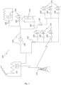
- the system includes a utility plant 101, supplying a utility such as water or district heating in form of thermal energy carried by a liquid e.g. water, via pipes of a utility distribution network 102 to a plurality of consumption site networks 103.
- the liquid passes through pumps 104 and valves 105 when propagating through the utility distribution network. Regulation of the pumps 104 and opening or closing of valves 105 may generate pressure transients, which are undesired events and may damage or deteriorate the utility distribution network.
- the consumption site network typically also includes valves, which when opened or closed may cause pressure transients in the liquid flowing in the utility distribution network.
- the utility distribution network is connected to the consumption site network via a utility meter 200, such as a water meter or a district heating meter / thermal energy meter.
- the utility meter 200 is arranged to measure the amount of liquid delivered from the utility distribution network 102 to the consumption site network 103.
- the utility meters 200 are arranged to detect pressure transients generated in the utility distribution network 102 or consumption site network 103 and optionally to transmit information about detected pressure transients to a head end system 111 via a meter reading infrastructure 110.
- the distribution network 102 and consumption side network 103 will include forward and return pipes (not shown).
- this description only refers to the utility distribution network and a single pipe, but it is to be understood as including forward and/or return pipes in a district heating distribution network.
- the flow may be measured in the forward pipe or the return pipe or in both pipes.
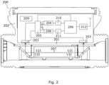
- the utility meter 200 comprises a flow tube 201 which may have threads or flanges for connection of the flow tube 201 to a utility distribution network 102 and a consumption site network 103 so that liquid can flow between the two networks.
- the utility meter comprises a closed meter housing 202 attached to the flow tube 201.
- Two piezo electric ultrasonic transducers 203 are arranged inside the meter house 202 on a wall of the flow tube 201 which passes through the meter housing.
- the piezoelectric ultrasonic transducers 203 are electrically connected to a first measurement circuit 204 via one or more switches 205 controlled by a digital processing unit 206.
- the digital processing unit 206 controls the first measurement circuit 204 to transmit ultrasonic signals 207 through a wall of the flow tube 201 into the liquid in the flow tube and to receive ultrasonic signals 207 having propagated through the liquid. Based on transit time or phase difference measurements of the ultrasonic signals 207 propagating through the liquid, the digital processing unit 206 can calculate the flowrate of the liquid.
- the ultrasonic signals are received via a first measurement circuit 204 and sampled with a sufficiently high sampling rate and converted to digital signals by a first analogue to digital converter 210 before they are processed by the digital processing unit for calculating the flow rate.
- the piezoelectric ultrasonic transducers 203, the switches 205, the first and the second measurement circuit 204, 208, the analogue to digital converters 210, 211, the digital processing unit 206, the communication interface 212, the battery 209 and other electronic components of the utility meter are arranged inside the meter housing 202, which protects them from the environment, especially form humidity in the environment.
- the utility meter is supplied with energy by the battery 209 arranged inside the meter housing.
- the piezo electric ultrasonic transducers 203 which are attached to a wall of the flow tube 201 will be subject to a change in strain when a pressure transient occurs in the liquid flowing in flow tube.
- the pressure transient in the liquid will deform the flow tube and the piezo electric ultrasonic transducers attached to it.
- the piezo electric transduces may be arranged in or at a trough going hole in a wall of the flow tube, in that case the transducers are protected from the liquid in the flow tube by a membrane or a transducer housing, changes in pressure of the liquid in the flow tube will in that case deform the membrane or transducer housing whereby the piezo electric transducers are subject to a change in strain.
- the piezo electric ultrasonic transducers 203 may be glued to the flow tube 201 or membrane and/or be mechanically pressed against the flow tube or membrane e.g. by a spring load.
- the change in strain of the piezo electric ultrasonic transducer 203 will result in an electrical charge 502 being build up on the piezoelectric ultrasonic transducers.
- the charge on the piezoelectric ultrasonic transducers will be indicative of the pressure transient amplitude.
- the piezoelectric ultrasonic transducers 203 are electrically connected to a second measurement circuit 208 via the one or more switches 205 controlled by the digital processing unit 206.
- the second measurement circuit is arranged to detect a change in electrical charge and thereby detect a pressure transient.
- the second measurement circuit 208 may be constructed using an operational amplifier to implement a voltage amplifier with a high input impedance or alternatively a charge amplifier.
- the second measurement circuit may be based on a commercially available operational amplifier such as the TLV8802 from Texas Instruments.
- the second measurement circuit includes a hold circuit such as a peak detector for generating an analogue output signal indicative of the maximum pressure amplitude.
- the second measurement circuit generates and holds an analogue output signal 501 indicative of or proportional to the maximum pressure transient amplitude measured.
- Fig. 5 illustrates the analogue output signal 501 from the second measurement circuit 208 and the charge 502 build-up on the piezo electric ultrasonic transducer 203 in response to a pressure transient.
- the maximum amplitude 503, which is indicative of a pressure transient is held by the second analogue measurement circuit even after the strain of the piezo electric transducer is no longer present and the resulting charge has diminished.
- the value of the analogue output signal 501 may be digitized by a second analogue to digital converter 211 to have a digital representation of the output value. Alternatively the first analogue to digital converter 210 may be reused.
- the second analogue measurement circuit includes a reset circuit for resetting or clearing the analogue output signal to a predefined value. When resetting the second measurement circuit the current pressure in the flow tube will become a new base line for detection of pressure transients.
- the analogue second measurement circuit is arranged for using both the first and the second piezoelectric ultrasonic transducer simultaneously for detecting a pressure transient.
- the analogue second measurement circuit may determine if the pressure transient is positive or negative based on signals received via the opposite polarized piezoelectric ultrasonic transducers.
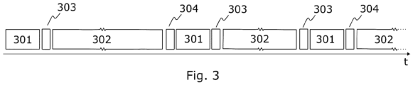
- the utility meter 200 is arranged to operate the first measurement circuit 204 to do a finite duration flow rate measurement 301 of the flow rate of the liquid in the flow tube 201 with regular or irregular intervals.
- a typical interval for finite duration flow rate measurement 301 in a water meter is typically 0.5-5 seconds.
- thermal energy meters may use longer intervals for the flow rate measurements 301.
- an intermediate pressure transient detection 302 is made in the time period in between two finite duration flow rate measurements 301.
- the utility meter When finishing a finite duration flow rate measurement 301 the utility meter operates the switches 205 to disconnect the first measurement circuit 204 and connect the second 208 measurement circuit to the piezoelectric ultrasonic transducers 203. Further, the first measurement circuit is powered down or put in a low power mode to reduce energy consumption. Before starting the intermediate pressure transient detection 302 the second measurement circuit is reset 303 so that the present pressure in the flow tube will be a new baseline for pressure transient detection. Before the next finite duration flow rate measurement 301 the analogue output of the second measurement circuit is digitized 304 whereby a digital representation of the output value is obtained. The digital representation may be stored in a memory of the digital processing unit.
- the utility meter operates the switches 205 to connect the first measurement circuit to 204 and disconnect the second 208 measurement circuit from the piezoelectric ultrasonic transducers. Due to the low energy consumption of the analogue second measurement circuit the overall energy consumption is kept low. Preferably the first measurement circuit is switched off or made powerless when operating the second measurement circuit and vice versa.
- the time periods of the intermediate pressure transient detection 302 are longer than the time periods of finite duration flow rate measurements. It is noted that fig. 3 is out of scale for illustrative purposes and that the duration of the intermediate pressure transient detection are much longer than time periods for finite duration flow rate measurements.
- a finite duration flow rate measurement will typically have a duration of 1- 20 milli seconds whereas the duration of the intermediate pressure transient detection typically will be in the range of 0.5 - 5 seconds.
- the utility meter 200 is arranged to determine an origin of a detected pressure transient by analysing at least two adjacent finite duration flow rate measurements 301 in between which the pressure transient is detected.
- the digital processing unit 206 includes a SW algorithm which subtracts the value of the adjacent finite duration flow rate measurements and based on the result determines the origin of the detected pressure transient.
- Pressure transients having an origin in the consumption site network 103 are typically related to changes in consumption e.g. when a tap or valve at the consumer is rapidly opened or closed. Consequently, if a pressure transient detected in a utility meter 200 is coincident with a change in consumption detected by the utility meter the pressure transient is determined to have its origin in the consumption site network 103. On the contrary, if there is no change of consumption the pressure transient has most likely reached the utility meter 200 via the utility distribution network 102 and in that case the origin of the pressure transient is determined to be in the utility distribution network.
- Fig. 4 illustrates an embodiment of a method for detecting pressure transients by a battery supplied utility meter 200 as illustrated in fig. 2 .
- the method is implemented in the digital processing unit of the utility meter and uses the piezoelectric ultrasonic transducers and the first and second measurement circuits.
- a first step 401 of the method the first and a second piezoelectric ultrasonic transducers arranged at the flow tube and the first measurement circuit, and the digital processing unit is operated with regular or irregular time intervals to perform a finite duration flow rate measurement of the liquid in the flow tube.
- a second step of the method 402 the analogue second measurement circuit, and at least the first or the second piezo electric transducer is operated in a time period in between two adjacent finite duration flow rate measurements of the first step 401 to perform an intermediate pressure transient detection.
- the second measurement circuit is operated to measure a pressure transient amplitude and generate and hold an analogue output signal proportional to a maximum pressure transient amplitude measured during said time period.
- an analogue to digital conversion of the analogue output signal is made at the end of said time period.
- the analogue output signal is reset or cleared at the beginning and/or the end of said time period.
- an origin of a pressure transient source is determined to be the utility distribution network or the consumption site network, based on at least the two adjacent finite duration flow rate measurements in between which the intermediate pressure transient detection is performed. The two adjacent finite duration flow rate measurements are subtracted to determine the origin as described above.
- the second measurement circuit is electrically disconnected from the piezoelectric ultrasonic transducers when operating the first measurement circuit to perform a finite duration flow rate measurement and / or first measurement circuit is disconnected from the piezoelectric ultrasonic transducers when operating the second measurement circuit to perform an intermediate pressure transient detection.
- fig. 1 discloses an embodiment of a pressure transient detection system with a plurality of utility meters 200 as described with reference to fig. 2 .
- the utility meters are arranged to interconnect a utility distribution network 102 and a plurality of consumption site networks 103.
- the utility meters include a wireless communication interface 212 arranged for transmitting information about a detected pressure transient to a head end system.
- the wireless communication interface 212 is implemented according to a communication protocol in order to interface a meter reading infrastructure arranged for wirelessly receiving information about a detected pressure transients from the plurality of utility meters.
- the communication wireless interface 212 and meter reading infrastructure 110 may be implemented according to a proprietary communication protocol or a standardized protocol such as wireless MBus EN13757, LoRa WAN, Bluetooth, Zigbee or cellular communication infrastructures such as NB-IOT, LTE cat. NB or cat. M.
- the information about detected pressure transients is forwarded to a head end system 111, which is arranged for correlating information about detected pressure transients received from at least two of the plurality of utility meters to determine an origin of a pressure transient.
- the information about the detected pressure transients may include detailed event information such as the amplitude, duration and absolute or relative time of the pressure transient event.
- the head end system is arranged to receive geographical and topology information about the utility distribution network and to include this information in the analysis of and correlation of the information about the pressure transients whereby the determination of the origin of a pressure transient is improved.
- the head end system 111 is implemented in a server or a computer system controlled by the utility company and the results of the correlation are presented to a user of the system in a table or on a GIS map showing also the utility distribution network.
- the invention can be implemented by means of hardware, software, firmware or any combination of these.
- the invention or some of the features thereof can also be implemented as software running on one or more data processors and/or digital signal processors.
- the individual elements of an embodiment of the invention may be physically, functionally and logically implemented in any suitable way such as in a single unit, in a plurality of units or as part of separate functional units.
- the invention may be implemented in a single unit, or be both physically and functionally distributed between different units and processors.
Landscapes
- Physics & Mathematics (AREA)
- Electromagnetism (AREA)
- Fluid Mechanics (AREA)
- General Physics & Mathematics (AREA)
- Measuring Volume Flow (AREA)
Priority Applications (3)
| Application Number | Priority Date | Filing Date | Title |
|---|---|---|---|
| EP23192892.0A EP4513149A1 (de) | 2023-08-23 | 2023-08-23 | Verbrauchszähler mit druckübergangserkennung |
| PCT/EP2024/073565 WO2025040752A1 (en) | 2023-08-23 | 2024-08-22 | Utility meter with pressure transient detection |
| EP24758844.5A EP4767022A1 (de) | 2023-08-23 | 2024-08-22 | Verbrauchszähler mit druckübergangserkennung |
Applications Claiming Priority (1)
| Application Number | Priority Date | Filing Date | Title |
|---|---|---|---|
| EP23192892.0A EP4513149A1 (de) | 2023-08-23 | 2023-08-23 | Verbrauchszähler mit druckübergangserkennung |
Publications (1)
| Publication Number | Publication Date |
|---|---|
| EP4513149A1 true EP4513149A1 (de) | 2025-02-26 |
Family
ID=87762815
Family Applications (2)
| Application Number | Title | Priority Date | Filing Date |
|---|---|---|---|
| EP23192892.0A Withdrawn EP4513149A1 (de) | 2023-08-23 | 2023-08-23 | Verbrauchszähler mit druckübergangserkennung |
| EP24758844.5A Pending EP4767022A1 (de) | 2023-08-23 | 2024-08-22 | Verbrauchszähler mit druckübergangserkennung |
Family Applications After (1)
| Application Number | Title | Priority Date | Filing Date |
|---|---|---|---|
| EP24758844.5A Pending EP4767022A1 (de) | 2023-08-23 | 2024-08-22 | Verbrauchszähler mit druckübergangserkennung |
Country Status (2)
| Country | Link |
|---|---|
| EP (2) | EP4513149A1 (de) |
| WO (1) | WO2025040752A1 (de) |
Citations (4)
| Publication number | Priority date | Publication date | Assignee | Title |
|---|---|---|---|---|
| CN100545588C (zh) * | 1999-06-24 | 2009-09-30 | 松下电器产业株式会社 | 流量计 |
| US20150378435A1 (en) * | 2008-01-04 | 2015-12-31 | Tactus Technology, Inc. | User interface system and method |
| WO2017005269A1 (en) * | 2015-07-03 | 2017-01-12 | Kamstrup A/S | System for monitoring a utility network |
| US20170153137A1 (en) * | 2014-06-20 | 2017-06-01 | Kamstrup A/S | System of ultrasonic consumption meters with pressure sensors |
-
2023
- 2023-08-23 EP EP23192892.0A patent/EP4513149A1/de not_active Withdrawn
-
2024
- 2024-08-22 WO PCT/EP2024/073565 patent/WO2025040752A1/en not_active Ceased
- 2024-08-22 EP EP24758844.5A patent/EP4767022A1/de active Pending
Patent Citations (4)
| Publication number | Priority date | Publication date | Assignee | Title |
|---|---|---|---|---|
| CN100545588C (zh) * | 1999-06-24 | 2009-09-30 | 松下电器产业株式会社 | 流量计 |
| US20150378435A1 (en) * | 2008-01-04 | 2015-12-31 | Tactus Technology, Inc. | User interface system and method |
| US20170153137A1 (en) * | 2014-06-20 | 2017-06-01 | Kamstrup A/S | System of ultrasonic consumption meters with pressure sensors |
| WO2017005269A1 (en) * | 2015-07-03 | 2017-01-12 | Kamstrup A/S | System for monitoring a utility network |
Also Published As
| Publication number | Publication date |
|---|---|
| WO2025040752A1 (en) | 2025-02-27 |
| EP4767022A1 (de) | 2026-07-01 |
Similar Documents
| Publication | Publication Date | Title |
|---|---|---|
| US9939344B2 (en) | Detecting leaks in a fluid distribution system | |
| EP3828511B1 (de) | Flüssigkeitsverbrauchsmesser mit geräuschsensor | |
| US11486787B2 (en) | Systems and methods for monitoring pressure transients and pipe bursts | |
| KR101454288B1 (ko) | 누수 탐지 시스템 | |
| US6404343B1 (en) | Water leakage monitoring apparatus | |
| AU2017341676A1 (en) | Vibration sensor for fluid leak detection | |
| CN104674229A (zh) | 地下管线阴极保护的智能化远程监测调控系统 | |
| CN108387288A (zh) | 水位计、水压传感器装置及水位测量系统 | |
| KR101072968B1 (ko) | 가스배관의 방식상태 진단용 전류/전위 감시장치 | |
| KR101352839B1 (ko) | 누수지점의 위치 검지 시스템 | |
| CN210319437U (zh) | 一种给水网管漏损检测系统 | |
| CN109444675A (zh) | 输电线路故障监测系统 | |
| KR20140063380A (ko) | 소음 수준 및 분포를 이용한 상시 누수진단 시스템 | |
| WO2023098073A1 (zh) | 一种城市地下综合管廊抗震性能异常预警系统及方法 | |
| JP2019148482A (ja) | 水環境センシング装置 | |
| CN107313052B (zh) | 一种管道阴极电位同步检测系统及检测方法 | |
| CN220063218U (zh) | 一种可装卸式有源无线测温螺帽 | |
| CN204702807U (zh) | 地下管线阴极保护的智能化远程监测调控系统 | |
| CN204256885U (zh) | 一种电力电缆的防外力破坏系统 | |
| WO2025040752A1 (en) | Utility meter with pressure transient detection | |
| KR101193546B1 (ko) | 누수 검지 장치 및 시스템 | |
| RU2380533C1 (ru) | Мобильная станция контроля параметров бурения | |
| CN201028286Y (zh) | 管道实时监控系统 | |
| Awawdeh et al. | Wireless sensing of flow-induced vibrations for pipeline integrity monitoring | |
| CN110275103A (zh) | 一种目标板功耗及电平时序检测系统 |
Legal Events
| Date | Code | Title | Description |
|---|---|---|---|
| PUAI | Public reference made under article 153(3) epc to a published international application that has entered the european phase |
Free format text: ORIGINAL CODE: 0009012 |
|
| STAA | Information on the status of an ep patent application or granted ep patent |
Free format text: STATUS: THE APPLICATION HAS BEEN PUBLISHED |
|
| AK | Designated contracting states |
Kind code of ref document: A1 Designated state(s): AL AT BE BG CH CY CZ DE DK EE ES FI FR GB GR HR HU IE IS IT LI LT LU LV MC ME MK MT NL NO PL PT RO RS SE SI SK SM TR |
|
| STAA | Information on the status of an ep patent application or granted ep patent |
Free format text: STATUS: THE APPLICATION IS DEEMED TO BE WITHDRAWN |
|
| 18D | Application deemed to be withdrawn |
Effective date: 20250827 |