EP4513183A1 - Système et procédé de mesure de concentration d'ions dans des échantillons de fluide - Google Patents
Système et procédé de mesure de concentration d'ions dans des échantillons de fluide Download PDFInfo
- Publication number
- EP4513183A1 EP4513183A1 EP24190005.9A EP24190005A EP4513183A1 EP 4513183 A1 EP4513183 A1 EP 4513183A1 EP 24190005 A EP24190005 A EP 24190005A EP 4513183 A1 EP4513183 A1 EP 4513183A1
- Authority
- EP
- European Patent Office
- Prior art keywords
- electrical potential
- calibration
- model
- fluid
- ion concentration
- Prior art date
- Legal status (The legal status is an assumption and is not a legal conclusion. Google has not performed a legal analysis and makes no representation as to the accuracy of the status listed.)
- Granted
Links
Images


Classifications
-
- G—PHYSICS
- G01—MEASURING; TESTING
- G01N—INVESTIGATING OR ANALYSING MATERIALS BY DETERMINING THEIR CHEMICAL OR PHYSICAL PROPERTIES
- G01N27/00—Investigating or analysing materials by the use of electric, electrochemical, or magnetic means
- G01N27/26—Investigating or analysing materials by the use of electric, electrochemical, or magnetic means by investigating electrochemical variables; by using electrolysis or electrophoresis
- G01N27/416—Systems
- G01N27/4163—Systems checking the operation of, or calibrating, the measuring apparatus
-
- G—PHYSICS
- G01—MEASURING; TESTING
- G01N—INVESTIGATING OR ANALYSING MATERIALS BY DETERMINING THEIR CHEMICAL OR PHYSICAL PROPERTIES
- G01N27/00—Investigating or analysing materials by the use of electric, electrochemical, or magnetic means
- G01N27/26—Investigating or analysing materials by the use of electric, electrochemical, or magnetic means by investigating electrochemical variables; by using electrolysis or electrophoresis
- G01N27/28—Electrolytic cell components
- G01N27/30—Electrodes, e.g. test electrodes; Half-cells
- G01N27/333—Ion-selective electrodes or membranes
Definitions
- the present disclosure relates to estimating the concentration of calcium ions within fluid samples. Particularly, but not exclusively, the present disclosure relates to a device and method for measuring the concentration of calcium ions within an unknown fluid relative to a calibration fluid; more particularly, but not exclusively, the present disclosure relates to a device and method for normalization of calcium ion concentration measurements obtained in relation to an unknown fluid and a calibration fluid.
- ISEs Polymer based ion-selective electrodes
- a fluid e.g., blood or other bodily fluid
- ISEs work on the principle of selective ion binding, where a membrane in the electrode selectively allows only a specific ion-i.e., a calcium ion (Ca2+)-within a fluid sample to pass through and thereby generate an electrical potential.
- the electrical potential generated is proportional to the concentration of the specific ion within the fluid sample.
- the electrical potential is read by a measuring instrument and is subsequently converted into a calcium ion concentration value (e.g., using a suitable Nernst equation).
- ISEs are typically used to monitor calcium levels within a patient's blood. Such measurements are important for diagnosing and managing medical conditions related to calcium imbalance such as kidney disorders, hypocalcemia, hypercalcemia, and bone disease (e.g., rickets).
- a waveform comprising a sequence of measurements of electrical potential is obtained from a sensor.
- the waveform comprises a calibration portion, corresponding to electrical potential measurements obtained whilst a calibration fluid passes over the sensor, and a sampling portion, corresponding to electrical potential measurements obtained whilst an unknown fluid passes over the sensor.
- the calibration portion and the sampling portion are separately modelled to determine an electrical potential difference which is subsequently normalized and used to determine the ion concentration in the unknown fluid.
- the present disclosure provides a device and method for measuring the ion concentration in an unknown fluid from electrical potential measurement obtained from the unknown fluid and a calibration fluid.
- a signal is obtained which comprises electrical potential (voltage) measurements obtained from the calibration fluid and electrical potential measurements obtained from the unknown fluid.
- the diffusion of the measurements during the transition from measuring the calibration fluid to measuring the unknown fluid is modelled using a first model.
- the drift of the measurements is modelled from the calibration fluid measurements using a second model.
- the first model is used to identify a value and corresponding time point at which the diffusion process has settled-i.e., when the electrical potential measurements are predicted to relate solely to the unknown fluid.
- a calibration electrical potential value is estimated at the corresponding time point and the difference between the identified value and the calibration electrical potential value is calculated to determine an electrical potential difference.
- This electrical potential difference is normalized by adjusting the difference by a shift amount determined in relation to the calibration electrical potential value and a predetermined electrical potential value. The normalized electrical potential difference is then used to determine the ion concentration of the unknown
- aspects of the present disclosure allow accurate and consistent measurements of the ion concentration of an unknown fluid to be determined from electrical potential measurements.
- a device such as a calcium ion-concentration device
- the method of the present disclosure improves the accuracy and performance of the device whilst also increasing the longevity of the device by allowing usable and accurate measurements to be obtained from sensors which are exhibiting drift or other gradual failures.
- the present disclosure allows for the sensitivity of a device's sensor(s) to be incorporated into the calculation of ion concentration thereby improving the accuracy of the reported measurements and providing an efficient mechanism for device calibration.
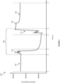
- the sampling portion 206 of the signal 202 (i.e., the portion of the signal 202 between time points t 2 and t 5 ) comprises a time-ordered sequence of electrical potential measurements obtained from the sensor as an unknown fluid passes over the sensor during the time period t 2 ⁇ t 5 .
- the sampling potion 206 of the signal 202 comprises two sub-portions: the first transition portion 210 and the second transition portion 212.
- the first transition portion 210 comprises a time-ordered sequence of electrical potential measurements which capture the change in device state as the sensor transitions from measuring the calibration fluid at time point t 2 to measuring the unknown fluid at time point t 3 .
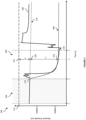
- the plot 300 comprises a signal 302, a calibration portion 304, and a sampling portion 306.
- the plot 300 further shows a diffusion model 308, a drift model 310, and a fixed electrical potential value 312.
- the plot 300 also shows a first transition point 314, a second transition point 316, a settled electrical potential value 318, and a calibration electrical potential value 320.
- the diffusion model 308 comprises a model fit to the sampling portion 306 of the signal 302 (i.e., fit to the measurements of the signal 302 between time point t 2 and t 4 ).
- the diffusion model 308 is used to model the diffusion process (or reverse diffusion process depending on whether there is an increase or decrease in ion concentration) as the sensor transitions from measuring the calibration fluid to measuring the unknown fluid.
- a sensor particularly an ion-selective electrode, exhibits a dominant exponential growth or decay when transitioning between measuring different fluids.
- the diffusion model 308 thus models the diffusion of the sensor measurements as the sensor assembly transitions from measuring the calibration fluid to measuring the unknown fluid.
- the diffusion model 308 is used to predict a point at which the sensory assembly has settled, and fully transitioned, to measuring the unknown fluid.
- the drift model 310 is fit by estimating the parameters of the model using the measurements of the signal 302 within the calibration portion 304. Once fit, the drift model 310 is used to obtain an estimated calibration measurement at the time point t a -i.e., the calibration electrical potential value 320, v ⁇ CAL .
- the electrical potential difference, v ⁇ between the settled electrical potential value 318, v ⁇ UNK , and the calibration electrical potential value 320, v ⁇ CAL , corresponds to the difference in electrical potential measurements used within the Nernst equations (such as that defined in Equation (1) above).
- the normalized electrical potential difference norm ( v ⁇ ) may be used directly in place of the voltage difference, v ⁇ , within the Nernst equation defined in Equation (1) above.
- an adapted, or modified, Nernst equation which is adapted to model a sensitivity of the sensor assembly may be used.
- the sensitivity of the sensor assembly is modelled based on a relationship between voltage (potential) and ion concentration.
- c is the bias (y-intercept) of the linear sensitivity model and s is the slope, or gradient, of the linear model.
- the linear sensitivity model may be fit using a plurality of historical measurements (i.e., historical electrical potential difference measurements with accompanying ion concentration values).
- a linear regression model may then be used to estimate the linear relationship between electrical potential difference measurements and ion concentration values.
- the bias and slope of the fit linear regression model may then be used within the modified Nernst equation in Equation (2) to estimate ion concentration iCa from normalized electrical potential difference norm ( v ⁇ ) .
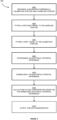
- the electrical potential difference is normalized by shifting the electrical potential difference by an offset value thereby generating a normalized electrical potential difference (i.e., a normalized voltage difference).
- the offset value corresponds to a difference between the calibration electrical potential value and a fixed electrical potential value (i.e., a predetermined voltage value).
- the fixed electrical potential value is a predetermined electrical potential value greater than 0V, and in one implementation is 5V.
- the ion concentration of the unknown fluid is calculated from the normalized electrical potential difference using a Nernst equation. Any of the Nernst equations described above in relation to Equations (1)-(3) may be used to determine the ion concentration of the unknown fluid from the normalized electrical potential difference.
- a modified Nernst equation may be used to determine the ion concentration of the unknown fluid from the normalized electrical potential difference.
- the modified Nernst equation is adapted to model a sensitivity of the sensor based on a relationship between electrical potential difference and ion concentration.
- the relationship may be linear (i.e., a linear model is used to model the sensitivity of the sensor) or nonlinear (i.e., a nonlinear model is used to model the sensitivity of the sensor).
- the method 400 may further comprise modelling the sensitivity of the sensor assembly using a plurality of historical electric potential difference measurements and corresponding ion concentrations using a regression algorithm, such as a Huber regressor (as described in more detail above in relation to Figure 3 ).
- a regression algorithm such as a Huber regressor (as described in more detail above in relation to Figure 3 ).
- the ion concentration of the unknown fluid is output.
- Outputting the ion concentration of the unknown fluid comprises outputting the ion concentration for display to a user (e.g., presenting the ion concentration on a display viewable to a user). Additionally, or alternatively, outputting the ion concentration of the unknown fluid comprises transmitting the ion concentration for further analysis or review.
- Figure 5 shows an example computing system for carrying out the methods of the present disclosure. Specifically, Figure 5 shows a block diagram of an embodiment of a computing system according to example embodiments of the present disclosure.
- Computing system 500 can be configured to perform any of the operations disclosed herein such as, for example, any of the operations discussed with reference to the functional units described in relation to Figure 1 (e.g., the external controller) or the steps discussed with reference to the method 400 shown in Figure 4 .
- Computing system includes one or more computing device(s) 502.
- the one or more computing device(s) 502 of computing system 500 comprise one or more processors 504 and memory 506.
- One or more processors 504 can be any general purpose processor(s) configured to execute a set of instructions.
- one or more processors 504 can be one or more general-purpose processors, one or more field programmable gate array (FPGA), and/or one or more application specific integrated circuits (ASIC).
- FPGA field programmable gate array
- ASIC application specific integrated circuits
- one or more processors 504 include one processor. Alternatively, one or more processors 504 include a plurality of processors that are operatively connected. One or more processors 504 are communicatively coupled to memory 506 via address bus 508, control bus 510, and data bus 512.
- Memory 506 can be a random access memory (RAM), a read only memory (ROM), a persistent storage device such as a hard drive, an erasable programmable read only memory (EPROM), and/or the like.
- the one or more computing device(s) 502 further comprise I/O interface 514 communicatively coupled to address bus 508, control bus 510, and data bus 512.
- Memory 506 can store information that can be accessed by one or more processors 504.
- memory 506 e.g., one or more non-transitory computer-readable storage mediums, memory devices
- the computer-readable instructions can be software written in any suitable programming language or can be implemented in hardware. Additionally, or alternatively, the computer-readable instructions can be executed in logically and/or virtually separate threads on one or more processors 504.
- memory 506 can store instructions (not shown) that when executed by one or more processors 504 cause one or more processors 504 to perform operations such as any of the operations and functions for which computing system 500 is configured, as described herein.
- memory 506 can store data (not shown) that can be obtained, received, accessed, written, manipulated, created, and/or stored.
- the one or more computing device(s) 502 can obtain from and/or store data in one or more memory device(s) that are remote from the computing system 500.
- Computing system 500 further comprises storage unit 516, network interface 518, input controller 520, and output controller 522.
- Storage unit 516, network interface 518, input controller 520, and output controller 522 are communicatively coupled to the central control unit (i.e., the memory 506, the address bus 508, the control bus 510, and the data bus 512) via I/O interface 514.
- the central control unit i.e., the memory 506, the address bus 508, the control bus 510, and the data bus 512
- Example 5 The device of example 3 wherein the relationship is nonlinear.
- Example 6 The device of any of examples 3 to 5 wherein the relationship between voltage and ion concentration is learnt from a plurality of historical measurements using a regression algorithm.
- Example 19 The computer-implemented method of any of examples 15 to 18 wherein the ion concentration of the unknown fluid is calculated from the normalized electrical potential difference using a Nernst equation.
Landscapes
- Chemical & Material Sciences (AREA)
- Life Sciences & Earth Sciences (AREA)
- Health & Medical Sciences (AREA)
- Physics & Mathematics (AREA)
- Chemical Kinetics & Catalysis (AREA)
- Electrochemistry (AREA)
- Molecular Biology (AREA)
- Analytical Chemistry (AREA)
- Biochemistry (AREA)
- General Health & Medical Sciences (AREA)
- General Physics & Mathematics (AREA)
- Immunology (AREA)
- Pathology (AREA)
- Investigating Or Analyzing Materials By The Use Of Electric Means (AREA)
Applications Claiming Priority (1)
| Application Number | Priority Date | Filing Date | Title |
|---|---|---|---|
| US18/456,402 US12601704B2 (en) | 2023-08-25 | 2023-08-25 | System and method for measurement of ion concentration in fluid samples |
Publications (2)
| Publication Number | Publication Date |
|---|---|
| EP4513183A1 true EP4513183A1 (fr) | 2025-02-26 |
| EP4513183B1 EP4513183B1 (fr) | 2025-10-15 |
Family
ID=91961954
Family Applications (1)
| Application Number | Title | Priority Date | Filing Date |
|---|---|---|---|
| EP24190005.9A Active EP4513183B1 (fr) | 2023-08-25 | 2024-07-22 | Système et procédé de mesure de concentration d'ions dans des échantillons de fluide |
Country Status (2)
| Country | Link |
|---|---|
| US (1) | US12601704B2 (fr) |
| EP (1) | EP4513183B1 (fr) |
Families Citing this family (1)
| Publication number | Priority date | Publication date | Assignee | Title |
|---|---|---|---|---|
| CN120594861B (zh) * | 2025-08-08 | 2025-12-09 | 辽宁元泓鑫润科技有限公司 | 一种基于传感器的流体上样动态校准方法及系统 |
Citations (3)
| Publication number | Priority date | Publication date | Assignee | Title |
|---|---|---|---|---|
| US20180259543A1 (en) * | 2017-03-07 | 2018-09-13 | Roche Diagnostics Operations, Inc. | Method of determining an analyte concentration |
| JP2020012823A (ja) * | 2018-07-10 | 2020-01-23 | キヤノンメディカルシステムズ株式会社 | 自動分析装置 |
| US20210318266A1 (en) * | 2018-09-13 | 2021-10-14 | Hitachi High-Tech Corporation | Electrolyte concentration measurement device |
Family Cites Families (5)
| Publication number | Priority date | Publication date | Assignee | Title |
|---|---|---|---|---|
| DE3032578C2 (de) | 1980-08-29 | 1983-11-03 | Battelle-Institut E.V., 6000 Frankfurt | Verfahren und Vorrichtung zur dynamischen und dichteunabhängigen Bestimmung des Massenstroms |
| US20080139951A1 (en) | 2006-12-08 | 2008-06-12 | Cardiac Pacemakers, Inc. | Detection of Stenosis |
| JP5033033B2 (ja) | 2008-03-27 | 2012-09-26 | 富士重工業株式会社 | 水平軸風車の乱流強度計測方法 |
| EP3546954B1 (fr) | 2016-01-07 | 2022-12-14 | Analog Devices, Inc. | Accéléromètre angulaire triaxial |
| US10746696B2 (en) | 2016-12-19 | 2020-08-18 | Analog Devices, Inc. | Self-calibrated heavy metal detector |
-
2023
- 2023-08-25 US US18/456,402 patent/US12601704B2/en active Active
-
2024
- 2024-07-22 EP EP24190005.9A patent/EP4513183B1/fr active Active
Patent Citations (3)
| Publication number | Priority date | Publication date | Assignee | Title |
|---|---|---|---|---|
| US20180259543A1 (en) * | 2017-03-07 | 2018-09-13 | Roche Diagnostics Operations, Inc. | Method of determining an analyte concentration |
| JP2020012823A (ja) * | 2018-07-10 | 2020-01-23 | キヤノンメディカルシステムズ株式会社 | 自動分析装置 |
| US20210318266A1 (en) * | 2018-09-13 | 2021-10-14 | Hitachi High-Tech Corporation | Electrolyte concentration measurement device |
Also Published As
| Publication number | Publication date |
|---|---|
| EP4513183B1 (fr) | 2025-10-15 |
| US20250067702A1 (en) | 2025-02-27 |
| US12601704B2 (en) | 2026-04-14 |
Similar Documents
| Publication | Publication Date | Title |
|---|---|---|
| ES2779349T3 (es) | Procedimiento de calibración para calibración prospectiva de un dispositivo de medición, programa informático y dispositivo de medición | |
| CN104048675B (zh) | 一种基于高斯过程回归的组合导航系统故障诊断方法 | |
| CA2843157C (fr) | Extrapolation de donnees de capteur interpolees pour augmenter un debit echantillon | |
| EP2208989A1 (fr) | Analyseur | |
| EP4513183B1 (fr) | Système et procédé de mesure de concentration d'ions dans des échantillons de fluide | |
| US20250299097A1 (en) | Time-series anomaly detection | |
| JP6228639B2 (ja) | 試料処理量を高めるための内挿センサデータの外挿 | |
| EP4502590A1 (fr) | Dispositif d'analyse d'électrolyte | |
| HK1248818A1 (zh) | 改进的生物传感器系统分析物测量 | |
| JP6462145B2 (ja) | 体液試料内の一時誤りを検出すること | |
| US20250146972A1 (en) | Electrolyte concentration measuring device and method for obtaining selectivity coefficient | |
| CN111788479B (zh) | 自动分析装置、自动分析方法 | |
| SE524574C2 (sv) | Metod för signalbehandling för voltammetri | |
| JPH05322843A (ja) | イオン電極を用いた電解質分析装置 | |
| US20230394359A1 (en) | Time series anomaly detection model training accelerator | |
| CN120643220B (zh) | 一种用于生物相容性多参数检测的数字处理系统 | |
| US20240280392A1 (en) | Bubble detection | |
| Sokolkov | Electrochemical Sensors for Digital Medicine and Biology Electrochemical Digitization of Analytical Information Biological Fluids Samples | |
| HU177028B (hu) | Elektroanalitikai mérőkészülék folyadékok és/vagy gázok összetevőinek és/vagy jellemzőinek meghatározására |
Legal Events
| Date | Code | Title | Description |
|---|---|---|---|
| PUAI | Public reference made under article 153(3) epc to a published international application that has entered the european phase |
Free format text: ORIGINAL CODE: 0009012 |
|
| STAA | Information on the status of an ep patent application or granted ep patent |
Free format text: STATUS: REQUEST FOR EXAMINATION WAS MADE |
|
| 17P | Request for examination filed |
Effective date: 20240722 |
|
| AK | Designated contracting states |
Kind code of ref document: A1 Designated state(s): AL AT BE BG CH CY CZ DE DK EE ES FI FR GB GR HR HU IE IS IT LI LT LU LV MC ME MK MT NL NO PL PT RO RS SE SI SK SM TR |
|
| GRAP | Despatch of communication of intention to grant a patent |
Free format text: ORIGINAL CODE: EPIDOSNIGR1 |
|
| STAA | Information on the status of an ep patent application or granted ep patent |
Free format text: STATUS: GRANT OF PATENT IS INTENDED |
|
| RIC1 | Information provided on ipc code assigned before grant |
Ipc: G01N 27/333 20060101ALN20250521BHEP Ipc: G01N 27/416 20060101AFI20250521BHEP |
|
| INTG | Intention to grant announced |
Effective date: 20250603 |
|
| GRAS | Grant fee paid |
Free format text: ORIGINAL CODE: EPIDOSNIGR3 |
|
| GRAA | (expected) grant |
Free format text: ORIGINAL CODE: 0009210 |
|
| STAA | Information on the status of an ep patent application or granted ep patent |
Free format text: STATUS: THE PATENT HAS BEEN GRANTED |
|
| AK | Designated contracting states |
Kind code of ref document: B1 Designated state(s): AL AT BE BG CH CY CZ DE DK EE ES FI FR GB GR HR HU IE IS IT LI LT LU LV MC ME MK MT NL NO PL PT RO RS SE SI SK SM TR |
|
| REG | Reference to a national code |
Ref country code: GB Ref legal event code: FG4D Ref country code: CH Ref legal event code: F10 Free format text: ST27 STATUS EVENT CODE: U-0-0-F10-F00 (AS PROVIDED BY THE NATIONAL OFFICE) Effective date: 20251015 |
|
| REG | Reference to a national code |
Ref country code: IE Ref legal event code: FG4D |
|
| REG | Reference to a national code |
Ref country code: DE Ref legal event code: R096 Ref document number: 602024000944 Country of ref document: DE |
|
| REG | Reference to a national code |
Ref country code: NL Ref legal event code: MP Effective date: 20251015 |
|
| REG | Reference to a national code |
Ref country code: AT Ref legal event code: MK05 Ref document number: 1847341 Country of ref document: AT Kind code of ref document: T Effective date: 20251015 |
|
| PG25 | Lapsed in a contracting state [announced via postgrant information from national office to epo] |
Ref country code: NL Free format text: LAPSE BECAUSE OF FAILURE TO SUBMIT A TRANSLATION OF THE DESCRIPTION OR TO PAY THE FEE WITHIN THE PRESCRIBED TIME-LIMIT Effective date: 20251015 |
|
| PG25 | Lapsed in a contracting state [announced via postgrant information from national office to epo] |
Ref country code: ES Free format text: LAPSE BECAUSE OF FAILURE TO SUBMIT A TRANSLATION OF THE DESCRIPTION OR TO PAY THE FEE WITHIN THE PRESCRIBED TIME-LIMIT Effective date: 20251015 |
|
| REG | Reference to a national code |
Ref country code: LT Ref legal event code: MG9D |
|
| PG25 | Lapsed in a contracting state [announced via postgrant information from national office to epo] |
Ref country code: NO Free format text: LAPSE BECAUSE OF FAILURE TO SUBMIT A TRANSLATION OF THE DESCRIPTION OR TO PAY THE FEE WITHIN THE PRESCRIBED TIME-LIMIT Effective date: 20260115 |
|
| PG25 | Lapsed in a contracting state [announced via postgrant information from national office to epo] |
Ref country code: HR Free format text: LAPSE BECAUSE OF FAILURE TO SUBMIT A TRANSLATION OF THE DESCRIPTION OR TO PAY THE FEE WITHIN THE PRESCRIBED TIME-LIMIT Effective date: 20251015 Ref country code: FI Free format text: LAPSE BECAUSE OF FAILURE TO SUBMIT A TRANSLATION OF THE DESCRIPTION OR TO PAY THE FEE WITHIN THE PRESCRIBED TIME-LIMIT Effective date: 20251015 Ref country code: AT Free format text: LAPSE BECAUSE OF FAILURE TO SUBMIT A TRANSLATION OF THE DESCRIPTION OR TO PAY THE FEE WITHIN THE PRESCRIBED TIME-LIMIT Effective date: 20251015 |
|
| PG25 | Lapsed in a contracting state [announced via postgrant information from national office to epo] |
Ref country code: RS Free format text: LAPSE BECAUSE OF FAILURE TO SUBMIT A TRANSLATION OF THE DESCRIPTION OR TO PAY THE FEE WITHIN THE PRESCRIBED TIME-LIMIT Effective date: 20260115 |
|
| PG25 | Lapsed in a contracting state [announced via postgrant information from national office to epo] |
Ref country code: IS Free format text: LAPSE BECAUSE OF FAILURE TO SUBMIT A TRANSLATION OF THE DESCRIPTION OR TO PAY THE FEE WITHIN THE PRESCRIBED TIME-LIMIT Effective date: 20260215 |
|
| PG25 | Lapsed in a contracting state [announced via postgrant information from national office to epo] |
Ref country code: PT Free format text: LAPSE BECAUSE OF FAILURE TO SUBMIT A TRANSLATION OF THE DESCRIPTION OR TO PAY THE FEE WITHIN THE PRESCRIBED TIME-LIMIT Effective date: 20260216 |
|
| PG25 | Lapsed in a contracting state [announced via postgrant information from national office to epo] |
Ref country code: PL Free format text: LAPSE BECAUSE OF FAILURE TO SUBMIT A TRANSLATION OF THE DESCRIPTION OR TO PAY THE FEE WITHIN THE PRESCRIBED TIME-LIMIT Effective date: 20251015 |
|
| PG25 | Lapsed in a contracting state [announced via postgrant information from national office to epo] |
Ref country code: LV Free format text: LAPSE BECAUSE OF FAILURE TO SUBMIT A TRANSLATION OF THE DESCRIPTION OR TO PAY THE FEE WITHIN THE PRESCRIBED TIME-LIMIT Effective date: 20251015 |