EP4513193A1 - Dispositif de stockage de conteneur et système d'analyse automatique - Google Patents
Dispositif de stockage de conteneur et système d'analyse automatique Download PDFInfo
- Publication number
- EP4513193A1 EP4513193A1 EP23790219.2A EP23790219A EP4513193A1 EP 4513193 A1 EP4513193 A1 EP 4513193A1 EP 23790219 A EP23790219 A EP 23790219A EP 4513193 A1 EP4513193 A1 EP 4513193A1
- Authority
- EP
- European Patent Office
- Prior art keywords
- power
- unit
- storage device
- requiring
- specimen
- Prior art date
- Legal status (The legal status is an assumption and is not a legal conclusion. Google has not performed a legal analysis and makes no representation as to the accuracy of the status listed.)
- Pending
Links
Images


Classifications
-
- G—PHYSICS
- G01—MEASURING; TESTING
- G01N—INVESTIGATING OR ANALYSING MATERIALS BY DETERMINING THEIR CHEMICAL OR PHYSICAL PROPERTIES
- G01N35/00—Automatic analysis not limited to methods or materials provided for in any single one of groups G01N1/00 - G01N33/00; Handling materials therefor
- G01N35/00584—Control arrangements for automatic analysers
- G01N35/00594—Quality control, including calibration or testing of components of the analyser
- G01N35/00712—Automatic status testing, e.g. at start-up or periodic
-
- G—PHYSICS
- G01—MEASURING; TESTING
- G01N—INVESTIGATING OR ANALYSING MATERIALS BY DETERMINING THEIR CHEMICAL OR PHYSICAL PROPERTIES
- G01N35/00—Automatic analysis not limited to methods or materials provided for in any single one of groups G01N1/00 - G01N33/00; Handling materials therefor
- G01N35/00584—Control arrangements for automatic analysers
- G01N35/00594—Quality control, including calibration or testing of components of the analyser
- G01N35/00613—Quality control
- G01N35/00623—Quality control of instruments
-
- G—PHYSICS
- G01—MEASURING; TESTING
- G01N—INVESTIGATING OR ANALYSING MATERIALS BY DETERMINING THEIR CHEMICAL OR PHYSICAL PROPERTIES
- G01N35/00—Automatic analysis not limited to methods or materials provided for in any single one of groups G01N1/00 - G01N33/00; Handling materials therefor
- G01N35/00584—Control arrangements for automatic analysers
- G01N35/00722—Communications; Identification
-
- G—PHYSICS
- G01—MEASURING; TESTING
- G01N—INVESTIGATING OR ANALYSING MATERIALS BY DETERMINING THEIR CHEMICAL OR PHYSICAL PROPERTIES
- G01N35/00—Automatic analysis not limited to methods or materials provided for in any single one of groups G01N1/00 - G01N33/00; Handling materials therefor
- G01N35/02—Automatic analysis not limited to methods or materials provided for in any single one of groups G01N1/00 - G01N33/00; Handling materials therefor using a plurality of sample containers moved by a conveyor system past one or more treatment or analysis stations
- G01N35/04—Details of the conveyor system
-
- G—PHYSICS
- G01—MEASURING; TESTING
- G01N—INVESTIGATING OR ANALYSING MATERIALS BY DETERMINING THEIR CHEMICAL OR PHYSICAL PROPERTIES
- G01N35/00—Automatic analysis not limited to methods or materials provided for in any single one of groups G01N1/00 - G01N33/00; Handling materials therefor
- G01N35/00584—Control arrangements for automatic analysers
- G01N35/0092—Scheduling
- G01N2035/0094—Scheduling optimisation; experiment design
-
- G—PHYSICS
- G01—MEASURING; TESTING
- G01N—INVESTIGATING OR ANALYSING MATERIALS BY DETERMINING THEIR CHEMICAL OR PHYSICAL PROPERTIES
- G01N35/00—Automatic analysis not limited to methods or materials provided for in any single one of groups G01N1/00 - G01N33/00; Handling materials therefor
- G01N35/02—Automatic analysis not limited to methods or materials provided for in any single one of groups G01N1/00 - G01N33/00; Handling materials therefor using a plurality of sample containers moved by a conveyor system past one or more treatment or analysis stations
- G01N35/04—Details of the conveyor system
- G01N2035/046—General conveyor features
- G01N2035/0465—Loading or unloading the conveyor
-
- G—PHYSICS
- G01—MEASURING; TESTING
- G01N—INVESTIGATING OR ANALYSING MATERIALS BY DETERMINING THEIR CHEMICAL OR PHYSICAL PROPERTIES
- G01N35/00—Automatic analysis not limited to methods or materials provided for in any single one of groups G01N1/00 - G01N33/00; Handling materials therefor
- G01N35/02—Automatic analysis not limited to methods or materials provided for in any single one of groups G01N1/00 - G01N33/00; Handling materials therefor using a plurality of sample containers moved by a conveyor system past one or more treatment or analysis stations
- G01N35/04—Details of the conveyor system
- G01N2035/0474—Details of actuating means for conveyors or pipettes
- G01N2035/0491—Position sensing, encoding; closed-loop control
Definitions
- the invention relates to a container storage device and an automatic analysis system.
- An automatic analysis system includes an automatic analyzer that analyzes a specific component contained in a specimen such as blood or urine, various pretreatment devices that perform various types of pretreatment on the specimen, and a transport device that transports a specimen container containing the specimen to the automatic analyzer.
- a transport device is operable during maintenance of a certain device among a plurality of devices.
- the other mechanisms can operate while maintaining a specific mechanism.
- PTL 1 discloses that in a specimen treatment device including a plurality of mechanisms each having one function, power supply to a specific mechanism is stopped and power supply to another mechanism is continued, whereby the other mechanism can be operated while the specific mechanism is under maintenance.
- the mechanism includes a power-requiring unit that is to be maintained while operating by being supplied with power, and a power-free unit that is to be maintained without operating. When power supply to the specific mechanism is stopped, the power-requiring unit cannot be maintained.
- an object of the invention is to provide a container storage device and an automatic analysis system that can maintain not only a power-free unit but also a power-requiring unit.
- the invention provides a container storage device for storing a container, the container storage device including a plurality of mechanisms having a predetermined function and a control unit configured to control the mechanisms.
- the mechanisms include a power-requiring unit that requires power supply for maintenance and a power-free unit that does not require power supply for maintenance.
- the control unit cuts off communication with the power-requiring unit and the power-free unit and stops the power supply, and when the power-requiring unit is maintained, the control unit restarts the power supply to the power-requiring unit while cutting off the communication.
- the invention provides an automatic analysis system in which the container storage device is located between an automatic analyzer configured to analyze a specimen and a transport device configured to transport the specimen.
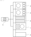
- the automatic analysis system illustrated in FIG. 1 includes an automatic analyzer 3, an input and collection device 2, a quality control specimen storage device 1, a transport device 4, and a system control device 5.
- the system control device 5 is a device that controls the automatic analyzer 3, the input and collection device 2, and the quality control specimen storage device 1, and is implemented by a computer, for example.
- An input and output device such as a keyboard, a mouse, a monitor, or a touch panel may be connected to the system control device 5. With the input and output device, an operation condition of the automatic analysis system is input or an operation state is displayed.
- the automatic analysis system may be provided with a pretreatment device that performs pretreatment such as centrifugation of blood, opening and closing of a specimen container, dispensing for subdividing a specimen, and sticking a label to a specimen container.
- the input and collection device 2, the quality control specimen storage device 1, the automatic analyzer 3, and the pretreatment device include a plurality of mechanisms having a predetermined function and a control unit configured to control the mechanisms.
- the quality control specimen storage device 1 is a container storage device, and the invention can be applied, as the container storage device, to the input and collection device 2, the automatic analyzer 3, and the pretreatment device that temporarily stores a container containing a liquid such as a specimen and reagent.
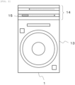
- the quality control specimen storage device 1 includes the storage mechanism 13 and the transport mechanism 14, and includes a control unit 10, a power source 11, and power source switching units 12a to 12d.
- the storage mechanism 13 includes a cold disk drive unit 20, a refrigerant shutter unit 21, and the like.
- the transport mechanism 14 includes a transfer line unit 22, a main line unit 23, and the like. Further, the units include control boards 30a to 30d, actuators 31a to 31d, and sensors 32a to 32d.
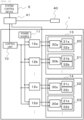
- the control unit 10 is a device configured to control an operation of each unit in accordance with a control signal transmitted from the system control device 5, and is, for example, a micro-processor unit (MPU).
- the power source 11 is a device configured to supply power to the units via the power source switching units 12a to 12d, and is a converter that converts a commercial voltage into a DC voltage, for example.
- the power source switching units 12a to 12d are circuits configured to switch whether to continue or stop the power supply from the power source 11 in accordance with a control signal transmitted from the control unit 10.
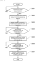
- the control unit 10 determines whether a maintenance start signal is received. S601 is repeated until the maintenance start signal is received. When the maintenance start signal is received, the process proceeds to S602.
- the maintenance start signal is transmitted from the system control device 5, which receives a maintenance start operation performed by the operator, to the control unit 10.
- the control unit 10 transmits a communication cutoff signal to the control boards 30a and 30b to stop a normal operation of the storage mechanism 13.
- the control unit 10 transmits a power stop signal to the power source switching units 12a and 12b, and stops power supply from the power source 11 to the storage mechanism 13. Due to the cutoff of communication between the control unit 10 and the storage mechanism 13 in S602 and the stop of power supply to the storage mechanism 13 in S603, the storage mechanism 13 is in a state in which the maintenance can be performed, and the refrigerant shutter unit 21 that is a power-free unit is maintained.
- the cold disk drive unit 20, which is a power-requiring unit, is in a state in which the maintenance can be performed after power supply is restarted. Since communication between the control unit 10 and the transport mechanism 14 is not cutoff and power supply to the transport mechanism 14 is not stopped, the transport mechanism 14 operates normally.
- the control unit 10 determines whether a maintenance completion signal of the power-free unit is received. S604 is repeated until the maintenance completion signal is received. When the maintenance completion signal is received, the process proceeds to S605.
- the maintenance completion signal is transmitted from the system control device 5, which receives a maintenance completion operation performed by the operator, to the control unit 10.
- the control unit transmits a power supply signal to the power source switching units 12a and 12b, and restarts the power supply from the power source 11 to the storage mechanism 13. Due to the restart of the power supply to the storage mechanism 13 in S605, the cold disk drive unit 20, which is a power-requiring unit, is in a state in which the maintenance can be performed.
- a program for performing a specialized operation when the power-requiring unit is maintained is executed.
- the program may be stored in a portable recording medium such as an SD card, and may be executed when the portable recording medium is inserted into the control boards 30a to 30d.
- the control unit 10 determines whether a maintenance completion signal of the power-requiring unit is received. S606 is repeated until the maintenance completion signal is received. When the maintenance completion signal is received, the process proceeds to S607.
- the maintenance completion signal is transmitted from the system control device 5, which receives a maintenance completion operation performed by the operator, to the control unit 10.
- the control unit 10 transmits a communication restart signal to the control boards 30a and 30b, and restarts a normal operation of the storage mechanism 13.
- the processing flow described with reference to FIG. 6 not only the power-free unit of the storage mechanism 13 but also the power-requiring unit can be maintained. Since the transport mechanism 14 can be normally operated during the maintenance of the storage mechanism 13, the downtime of the automatic analysis system can be reduced.
- the description is made in which a maintenance program of the power-requiring unit stored in a portable recording medium is executed by the control boards 30a to 30d.
- description will be made in which an external PC storing the maintenance program of the power-requiring unit is connected to each of the control boards 30a to 30d.
- FIG. 7 A detailed configuration of the second embodiment will be described with reference to FIG. 7 .
- an external PC 40 is added to the configuration in FIG. 5 , and thus the external PC 40 will be described.
- the external PC 40 is, for example, a notebook computer, and stores a program for performing a specialized operation when the power-requiring unit is maintained.
- the external PC 40 is used by being connected to a unit to be maintained, for example, the control board 30a of the cold disk drive unit 20.
- a flow of maintenance processing in the second embodiment is based on that in the first embodiment. That is, in a state where communication between the control unit 10 and the storage mechanism 13 is cut off and power supply to the storage mechanism 13 is stopped, the refrigerant shutter unit 21, which is a power-free unit, is maintained. The transport mechanism 14 operates normally. Then, after the power supply to the storage mechanism 13 is restarted, the maintenance program stored in the external PC 40 connected to the control board 30a is executed to maintain the cold disk drive unit 20 that is the power-requiring unit. When the maintenance of the power-free unit and the power-requiring unit is completed, the communication between the control unit 10 and the storage mechanism 13 is restarted, and the storage mechanism 13 returns to the normal operation.
- the power-free unit similarly to the first embodiment, not only the power-free unit but also the power-requiring unit can be maintained, and since another mechanism can operate normally during the maintenance, the downtime of the automatic analysis system can be reduced.
- the description is made in which the external PC 40 storing the maintenance program of the power-requiring unit is connected to each of the control boards 30a to 30d.
- description will be made in which the external PC 40 and the control boards 30a to 30d are connected via a switching hub.
- FIG. 8 A detailed configuration of the third embodiment will be described with reference to FIG. 8 .
- a switching hub 41 is added to the configuration in FIG. 7 , and thus the switching hub 41 will be described.
- the switching hub 41 is a circuit configured to switch a transmission destination of a control signal, is installed between the system control device 5 and the control unit 10, and is connected to all control boards 30a to 30d.
- the external PC 40 in which the maintenance program is stored is connected to the switching hub 41.
- the switching hub 41 performs switching so that the unit to be maintained, for example, the control board 30a of the cold disk drive unit 20 is the transmission destination of the control signal.
- a flow of the maintenance processing in the third embodiment is also based on that in the first embodiment. That is, in a state where communication between the control unit 10 and the storage mechanism 13 is cut off and power supply to the storage mechanism 13 is stopped, the refrigerant shutter unit 21, which is a power-free unit, is maintained. The transport mechanism 14 operates normally. Then, after the power supply to the storage mechanism 13 is restarted, the maintenance program stored in the external PC 40 connected to the control board 30a via the switching hub 41 is executed to maintain the cold disk drive unit 20 that is the power-requiring unit. When the maintenance of the power-free unit and the power-requiring unit is completed, the communication between the control unit 10 and the storage mechanism 13 is restarted, and the storage mechanism 13 returns to the normal operation.
- the third embodiment similarly to the first embodiment, not only the power-free unit but also the power-requiring unit can be maintained, and since another mechanism can operate normally during the maintenance, the downtime of the automatic analysis system can be reduced. Since the switching hub 41 is used, it is not necessary to reconnect the external PC 40 every time the unit to be maintained changes, and thus the labor of the operator can be reduced.
Landscapes
- Physics & Mathematics (AREA)
- Health & Medical Sciences (AREA)
- Life Sciences & Earth Sciences (AREA)
- Chemical & Material Sciences (AREA)
- Analytical Chemistry (AREA)
- Biochemistry (AREA)
- General Health & Medical Sciences (AREA)
- General Physics & Mathematics (AREA)
- Immunology (AREA)
- Pathology (AREA)
- Engineering & Computer Science (AREA)
- Quality & Reliability (AREA)
- Automatic Analysis And Handling Materials Therefor (AREA)
Applications Claiming Priority (2)
| Application Number | Priority Date | Filing Date | Title |
|---|---|---|---|
| JP2022068149 | 2022-04-18 | ||
| PCT/JP2023/005622 WO2023203854A1 (fr) | 2022-04-18 | 2023-02-17 | Dispositif de stockage de conteneur et système d'analyse automatique |
Publications (1)
| Publication Number | Publication Date |
|---|---|
| EP4513193A1 true EP4513193A1 (fr) | 2025-02-26 |
Family
ID=88419664
Family Applications (1)
| Application Number | Title | Priority Date | Filing Date |
|---|---|---|---|
| EP23790219.2A Pending EP4513193A1 (fr) | 2022-04-18 | 2023-02-17 | Dispositif de stockage de conteneur et système d'analyse automatique |
Country Status (5)
| Country | Link |
|---|---|
| US (1) | US20250199021A1 (fr) |
| EP (1) | EP4513193A1 (fr) |
| JP (1) | JP7745093B2 (fr) |
| CN (1) | CN119096145A (fr) |
| WO (1) | WO2023203854A1 (fr) |
Family Cites Families (5)
| Publication number | Priority date | Publication date | Assignee | Title |
|---|---|---|---|---|
| JP2009008558A (ja) * | 2007-06-28 | 2009-01-15 | A & T Corp | 分注装置、検体検査システム、分注方法、検体検査方法、分注プログラム、検体検査プログラム |
| WO2012120755A1 (fr) * | 2011-03-04 | 2012-09-13 | 株式会社 日立ハイテクノロジーズ | Dispositif d'analyse |
| WO2014112259A1 (fr) * | 2013-01-15 | 2014-07-24 | 株式会社 日立ハイテクノロジーズ | Système de traitement d'échantillon |
| JP6358527B2 (ja) * | 2013-11-15 | 2018-07-18 | 株式会社サキコーポレーション | 検査装置 |
| CN115485566A (zh) * | 2020-05-29 | 2022-12-16 | 株式会社日立高新技术 | 自动分析装置以及自动分析装置中的维护方法 |
-
2023
- 2023-02-17 EP EP23790219.2A patent/EP4513193A1/fr active Pending
- 2023-02-17 CN CN202380031992.1A patent/CN119096145A/zh active Pending
- 2023-02-17 US US18/851,788 patent/US20250199021A1/en active Pending
- 2023-02-17 JP JP2024516101A patent/JP7745093B2/ja active Active
- 2023-02-17 WO PCT/JP2023/005622 patent/WO2023203854A1/fr not_active Ceased
Also Published As
| Publication number | Publication date |
|---|---|
| JPWO2023203854A1 (fr) | 2023-10-26 |
| WO2023203854A1 (fr) | 2023-10-26 |
| CN119096145A (zh) | 2024-12-06 |
| US20250199021A1 (en) | 2025-06-19 |
| JP7745093B2 (ja) | 2025-09-26 |
Similar Documents
| Publication | Publication Date | Title |
|---|---|---|
| US8409507B2 (en) | Automatic analyzer | |
| EP0871034B1 (fr) | Appareil d'analyses automatisé | |
| CN113692537B (zh) | 自动分析装置以及自动分析装置中的维护引导方法 | |
| CN107850608A (zh) | 自动分析装置 | |
| JP2939162B2 (ja) | 検体搬送システムにおける処理装置 | |
| CN110231491A (zh) | 样本分析系统及其节能控制方法 | |
| CN115485566A (zh) | 自动分析装置以及自动分析装置中的维护方法 | |
| EP4513193A1 (fr) | Dispositif de stockage de conteneur et système d'analyse automatique | |
| US20040096361A1 (en) | Automatic analyzer | |
| JP2002357612A (ja) | 検体処理システム | |
| EP4024050B1 (fr) | Analyseur automatisé | |
| JP6453078B2 (ja) | 検体処理システム | |
| EP3940387B1 (fr) | Dispositif d'analyse automatique et procédé d'analyse automatique | |
| US9430025B2 (en) | Method for temporary operation of an automated analysis device in a standby mode | |
| JP6143549B2 (ja) | 検体処理システム | |
| EP4089417A1 (fr) | Dispositif d'analyse automatique, système d'affichage de dispositif d'analyse automatique et procédé de réalisation d'affichage dans un dispositif d'analyse automatique | |
| CN114578072A (zh) | 样本分析设备的控制方法 | |
| CN114174835B (zh) | 自动分析装置 | |
| US20250138038A1 (en) | Automatic analysis system | |
| WO2021002050A1 (fr) | Analyseur automatisé et procédé d'affichage de dispositif d'affichage d'analyseur automatisé | |
| CN112534269B (zh) | 自动分析装置以及自动分析系统 | |
| CN119224346A (zh) | 样本检验系统及样本通道的配置方法 |
Legal Events
| Date | Code | Title | Description |
|---|---|---|---|
| STAA | Information on the status of an ep patent application or granted ep patent |
Free format text: STATUS: UNKNOWN |
|
| STAA | Information on the status of an ep patent application or granted ep patent |
Free format text: STATUS: THE INTERNATIONAL PUBLICATION HAS BEEN MADE |
|
| PUAI | Public reference made under article 153(3) epc to a published international application that has entered the european phase |
Free format text: ORIGINAL CODE: 0009012 |
|
| STAA | Information on the status of an ep patent application or granted ep patent |
Free format text: STATUS: REQUEST FOR EXAMINATION WAS MADE |
|
| 17P | Request for examination filed |
Effective date: 20241118 |
|
| AK | Designated contracting states |
Kind code of ref document: A1 Designated state(s): AL AT BE BG CH CY CZ DE DK EE ES FI FR GB GR HR HU IE IS IT LI LT LU LV MC ME MK MT NL NO PL PT RO RS SE SI SK SM TR |
|
| DAV | Request for validation of the european patent (deleted) | ||
| DAX | Request for extension of the european patent (deleted) |