EP4513277A1 - Halterung für eine abnehmbare uhr - Google Patents
Halterung für eine abnehmbare uhr Download PDFInfo
- Publication number
- EP4513277A1 EP4513277A1 EP23192727.8A EP23192727A EP4513277A1 EP 4513277 A1 EP4513277 A1 EP 4513277A1 EP 23192727 A EP23192727 A EP 23192727A EP 4513277 A1 EP4513277 A1 EP 4513277A1
- Authority
- EP
- European Patent Office
- Prior art keywords
- support
- applicator
- locking
- sensor
- support according
- Prior art date
- Legal status (The legal status is an assumption and is not a legal conclusion. Google has not performed a legal analysis and makes no representation as to the accuracy of the status listed.)
- Withdrawn
Links
Images

Classifications
-
- G—PHYSICS
- G04—HOROLOGY
- G04B—MECHANICALLY-DRIVEN CLOCKS OR WATCHES; MECHANICAL PARTS OF CLOCKS OR WATCHES IN GENERAL; TIME PIECES USING THE POSITION OF THE SUN, MOON OR STARS
- G04B37/00—Cases
- G04B37/04—Mounting the clockwork in the case; Shock absorbing mountings
- G04B37/0427—Mountings relative to pocket and wrist watches allowing a rocking movement about a hinge or any other movement
-
- A—HUMAN NECESSITIES
- A61—MEDICAL OR VETERINARY SCIENCE; HYGIENE
- A61B—DIAGNOSIS; SURGERY; IDENTIFICATION
- A61B5/00—Measuring for diagnostic purposes; Identification of persons
- A61B5/145—Measuring characteristics of blood in vivo, e.g. gas concentration or pH-value ; Measuring characteristics of body fluids or tissues, e.g. interstitial fluid or cerebral tissue
- A61B5/14532—Measuring characteristics of blood in vivo, e.g. gas concentration or pH-value ; Measuring characteristics of body fluids or tissues, e.g. interstitial fluid or cerebral tissue for measuring glucose, e.g. by tissue impedance measurement
-
- A—HUMAN NECESSITIES
- A61—MEDICAL OR VETERINARY SCIENCE; HYGIENE
- A61B—DIAGNOSIS; SURGERY; IDENTIFICATION
- A61B5/00—Measuring for diagnostic purposes; Identification of persons
- A61B5/68—Arrangements of detecting, measuring or recording means, e.g. sensors, in relation to patient
- A61B5/6801—Arrangements of detecting, measuring or recording means, e.g. sensors, in relation to patient specially adapted to be attached to or worn on the body surface
- A61B5/6802—Sensor mounted on worn items
- A61B5/681—Wristwatch-type devices
-
- G—PHYSICS
- G04—HOROLOGY
- G04B—MECHANICALLY-DRIVEN CLOCKS OR WATCHES; MECHANICAL PARTS OF CLOCKS OR WATCHES IN GENERAL; TIME PIECES USING THE POSITION OF THE SUN, MOON OR STARS
- G04B47/00—Time-pieces combined with other articles which do not interfere with the running or the time-keeping of the time-piece
- G04B47/06—Time-pieces combined with other articles which do not interfere with the running or the time-keeping of the time-piece with attached measuring instruments, e.g. pedometer, barometer, thermometer or compass
- G04B47/063—Time-pieces combined with other articles which do not interfere with the running or the time-keeping of the time-piece with attached measuring instruments, e.g. pedometer, barometer, thermometer or compass measuring physiological quantities, e.g. pedometers, heart-rate sensors, blood pressure gauges and the like
Definitions
- the present invention relates to a support adapted to removably receive a timepiece such as a watch.
- the invention also relates to a timepiece comprising a removable fixing device allowing it to be fixed on such a support. It further relates to the combination of such a support with such a timepiece.
- the support according to the present invention is further adapted to the centering or guiding of a medical sensor application device such as a blood glucose sensor.
- the present invention further relates to a method of implanting a physiological sensor using such a support.
- Blood glucose sensors such as those developed by Abbott can be placed directly on the patient's skin and thus allow continuous monitoring of blood glucose levels.
- Such sensors often come in the form of a patch with a flexible filament on its front side, which can be inserted under the skin to capture the desired parameters.
- Proper installation of such a sensor requires the use of an applicator by the user or the patient, who can then apply the sensor independently. However, positioning the applicator on oneself is not always easy. The final position of the sensor is then approximate.
- the applicator is designed to place the sensor on a discreet part of the patient, such as the back of the upper arm, which requires a certain flexibility on the part of the user. Depending on the person, the operation can be difficult or delicate. In addition, the sensor can remain visible to third parties.
- An aim of the present invention is to provide a device for removably attaching a timepiece or a piece of jewelry or any other object intended to be worn by a user.
- an aim of the present invention is to provide a device suitable for holding an object at a distance from the user's skin.
- Another objective is to propose a device suitable for masking a physiological sensor or a patch or any equivalent.
- Another objective of the present invention is to provide a guide or system for positioning a physiological sensor applicator.
- Another object of the present invention is to provide a method of applying a physiological sensor using an applicator.
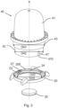
- the present description relates to a support 20 as illustrated by the figures 1 , 3 And 4 .
- the support 20 comprises a peripheral portion 21 delimiting an openwork space 25.
- the peripheral portion can take any suitable shape. It can be, for example, circular, oval, square, rectangular or mixed in shape.
- the peripheral portion 21 comprises an internal surface 200, oriented towards the openwork space 25.
- the internal surface 200 comprises an internal rim 22 forming a first flat 220.
- the first flat 220 is orthogonal to the internal surface 200 of the support.
- the internal surface 200 can be oriented vertically and the first flat 220 horizontally.
- the first flat 220 accommodates the lower surface 13 of an object 10 to be fixed to the support 20. This also represents the advantage of leaving a free space under the lower surface 13 of the object 10 when it is carried by a user.
- the free space is a function of the height H22 of the internal rim 22. It is typically between 1 millimeter and 10 millimeters, or of the order of 2 to 8 millimeters.
- the lower surface 13 of the object 10 is thus at a distance from the user's skin, which limits perspiration.
- the peripheral part 21 of the support can be solid or perforated with ventilation holes (not shown) allowing air to circulate under the lower surface 13 of the object 10.
- the internal surface 200 of the support 20 has a dimension D200 adapted to the dimension D11 of the external structure of the object 10 to be assembled to the support 20.
- the dimension D200 of the internal surface 200 corresponds to the dimension D11 of the external structure 11 of the object 10 , excluding mechanical clearances.
- the object 10 can be inserted into the space delimited by the internal surface 200 at least over a portion of its height H11 so as to rest on the first flat 220.
- the dimension D22 of the internal rim 22 is less than the dimension D11 of the external structure 11 of the object 10 to be assembled on the support 20.
- the height H22 of the internal rim 22 represents a fraction of the height H200 of the internal surface 200.
- the height H22 of the internal rim can be between 10% and 90% of the height H200 of the internal surface 200 , in particular of the order of 20%, 30%, 50%, 60% or 70%.
- the support 20 advantageously comprises a lower lip 23 arranged on the lower part of the peripheral structure 21.
- the lower lip 23 delimits an openwork space 25 of dimension D25.
- the support 20 is thus openwork so that once arranged on the user, his skin remains accessible through the central part of the support 20.
- the dimension D25 of the openwork space 25 represents a fraction of between 50% and 95%, preferably between 70% and 85%, or of the order of 75% or 80%, of the dimension D200 of the internal surface 200.
- the lip 23 forms a second flat 230.
- the support 20 comprises at least one holding device 26, allowing it to be placed on the user.
- the holding device 26 comprises two pairs of horns adapted to the attachment of a bracelet (not shown) allowing the support 20 to be attached to the user's wrist.
- Other holding devices can nevertheless be used as required.
- the support 20 comprises a locking device 240 making it possible to removably hold the object 10 to be assembled on the support 20.
- Any suitable locking device can be envisaged such as a screw thread, a bayonet system, one or more retractable lugs, a clip system involving for example a spring blade, or their combination, as well as any equivalent.
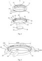
- the locking device 240 is similar to a bayonet system, illustrated by the Figures 1, 2a and 2b . It comprises for this purpose one, preferably two or more than two, lips of locking 241 arranged on a fraction of the internal surface 200 of the support 20.
- the locking lip(s ) 241 are arranged parallel to the first flat 220 so as to form a locking slide 244 delimited by the first flat 220. A surface other than the first flat may nevertheless be used for this purpose.
- the locking lip(s) 241 comprise a locking stop 242 at one of their ends, at least partially closing the locking slide 244.
- a locking lip according to the present description may comprise a bevel 243 oriented towards the locking slide 244 ( Figure 2a, 2b ).
- a locking lip according to the present invention may comprise a locking notch 245 ( figure 2b ) into which a lug or an equivalent part of the object 10 to be assembled to the support 20 can be inserted.
- the object 10 to be assembled to the support 20 comprises an external structure 11 whose dimension D11 is adapted to the support 20 described here.
- the external structure 11 may comprise a lower surface 13 delimiting the lower part of the object 10.
- the external structure 11 further comprises an anchoring device adapted to cooperate with the locking device 240 of the support 20.
- the external structure 13 comprises a complementary screw thread.
- the external structure 11 comprises at least one lug or lip capable of cooperating with the locking slide(s) of the support 20.
- the object 10 comprises the relief adapted to receive and hold the spring blade.
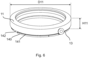
- the external structure 11 of the object 10 comprises in the lower position an anchoring base 140.
- the anchoring base 140 extends over a fraction of the periphery of the object 10 up to a fitting surface 142. It can take the form of a lip or a rim on the periphery of the external structure 11 adapted to be inserted into the locking slide 244 of the support 20.
- the anchoring base 140 can be limited to a lug whose diameter corresponds to the width of the locking slide 144. Such a lug can also be inserted into a locking notch 245 formed in the locking lip 241, for example at the end of the locking slide 244.
- several anchoring bases 140 are arranged around the perimeter of the external structure 11, i.e.
- the anchoring device of the object 10 further comprises an anchoring groove 141 allowing the sliding of the locking lip 241 of the support 20.
- the user can place the object 10 on the support 20, by making the interlocking surfaces 142 coincide with the locking lips 241 of the support 20 until its lower surface 13 rests on the first flat 220, then rotate it by an angle suitable for inserting the anchoring base(s ) 140 into the corresponding locking slides 244 up to their locking stop 242. The object 10 is thus secured on the support 20.
- the width of the locking slides 244 and the anchoring bases 141 can be adjusted so that the friction is sufficient to hold the object 10 in place.
- an elastic device for increasing friction such as a spring blade, may be provided.
- the support 20 may comprise, in addition to the locking device described here, a locking system 24 for better securing the object 10 on the support 20.
- a locking system may comprise, for example, one or more retractable balls or lugs arranged on a surface of the support 20. Such retractable balls or lugs may thus disappear into the support 20 upon contact with the object 10 and automatically emerge therefrom facing a cavity of the object 10 so as to lock it in position.
- a retractable ball or lug is associated with a spring adapted to maintain the ball or lug in a prominent position relative to the surface of the support 20.
- Such a ball or lug is generally known as a ratchet ball.
- the first flat 220 is provided with one or more of these retractable balls or lugs 24.
- the lower surface 13 of the object 10 is provided with cavities adapted to accommodate such retractable balls or lugs when the lower surface 13 rests on the first flat 220.
- the locking system 24 may be provided in addition to the locking stops 242 or as a replacement for the locking stops 242.
- the retractable balls may be arranged elsewhere than on the first flat 220, for example, on the internal surface 200; in this case, the corresponding cavities are arranged facing each other on the external structure 11 of the object 10.
- several retractable balls or lugs are arranged symmetrically so that the object 10 can be fixed to the support 20 in different orientations.
- the retractable balls or lugs are arranged non-symmetrically so as to serve as a foolproofing device. The object 10 is thus assembled to the support 20 in a single orientation.
- the locking lips 241 and the corresponding nesting surfaces 142 are arranged symmetrically so that the object 10 can be assembled to the support according to several different angular argentations.
- the locking lips 241 and the corresponding nesting surfaces 142 are arranged non-symmetrically so as to serve as a foolproofing device.
- the number of locking lips 241 in a locking device 240 may vary as required. For example, there may be two or three or four or more.
- the number of retractable balls or lugs of the locking system 24 may also vary according to requirements. According to one option, no locking system is provided. According to a preferred option, the locking system comprises one or two or three or four retractable balls or lugs. According to one variant, the arrangement of the retractable balls or lugs of the locking system locking 24 is reversed, so that the first flat 220 has cavities and the object 10 has such retractable balls or lugs.
- oblique threads can replace the locking lips 241 on the inner surface 200 and the anchoring base can take the form of complementary oblique threads, so as to produce a quarter-turn or third-turn system.
- the object 10 may designate any type of ornamental or utility object.
- the external structure 11 may serve as a case in which a jewel or a watch movement may be housed.
- the object 10 illustrated in more detail by the figure 7 , comprises a caliber 156, a dial 155 surmounted by hands 151 and a glass 150 and housed in the caseband 152 which acts as an external structure 11.
- the back 157 comprising a lower surface 13, also comprises the anchoring device 14. The back can for example be screwed onto the caseband or assembled in any other suitable manner.
- the invention according to the present description covers a modular assembly comprising the support 20 described here and an object 10 removably assembled to the support 20.
- an object 10 can be assembled to the support 20.
- an object 10 can be selected from a dial with digital or numeric display, a dial with mechanical display, a piece of jewelry, or a combination of several objects.
- the present invention also covers a kit or set comprising a support 20 as described herein and several different objects 10 which can be alternatively assembled to the support 20 in a removably manner.
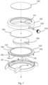
- the kit comprises, in addition to the support 20, one or more sensors 30 and one or more applicators 40 adapted to place the sensor 30 on the user.
- the support 20 described here has several functions.
- the first is to hold an object 10 on the user in a removable manner.
- Another function is to hold an object 10 on the user while leaving a free space between the object 10 and the user's skin.
- the free space is notably possible thanks to the inner rim 22, of a height D22, described above.
- the free space can be used to mask the presence of a sensor 30 or a patch or any other device for medical use or for other uses, on the user's skin.
- the dimension D25 of the openwork space 25 is thus provided for this purpose depending on the dimension of the patch or sensor to be placed on the user.
- the support 20 also serves as a guide or centering frame for applying a sensor 30 to the user's skin.
- the support 20 may comprise one or more guide surfaces 27 arranged on the internal surface 200.
- a guide surface 27 may consist of a rectilinear relief oriented transversely to the internal surface 200, i.e. vertically when the support 20 is arranged on the user.
- the relief of the guide surface 27 may comprise or consist of a groove, a lip, a lug, or any equivalent.
- Such a guide surface is therefore recessed or thickened relative to the internal surface 200. It also passes through the first flat 220 at least as far as the lower lip 23.
- the support 20 is thus compatible with the use of an applicator 40 comprising a gripping part 41, a base 43 and an applicator base 42.
- the applicator base 42 may comprise one or more reliefs complementary to the guide surfaces 27 of the support 20.
- the applicator 40 may be arranged in the support 20 and guided by the guide surface(s ) 27 of the support until it comes to bear on the lower lip 23.
- the support 20 is free of a lower lip 23 so that the applicator comes directly into contact with the user's skin. Actuation of the applicator then makes it possible to fix the sensor 30 on the user's skin in a precise and reproducible manner. The sensor 30 is then placed in the central position of the openwork space 25.
- the base 43 has a base dimension 43 corresponding to the internal rim dimension D22 of the support 20, excluding functional clearances.
- the present invention further covers a method for positioning a sensor 30 or an implant or any equivalent on a user.
- the method comprises a first step of placing and fixing the support 20 on the user, for example to one of his wrists.
- the holding device 26 is particularly suitable for this operation.
- the latter can prepare the applicator 40 with the appropriate sensor 30 and place the applicator 40 in contact with the support 20 so that the reliefs present at the base of the applicator complement the guide surface(s) 27.
- the user then exerts the necessary pressure on the applicator to fix the sensor 30 correctly.
- the method comprises a step of fixing an object 10 on the support so that the sensor 30 is no longer visible to a third party.
- the object 10 comprises a module for displaying medical or physiological data such as those measured by the sensor 30.
- the sensor 30 can be provided for this purpose with a suitable data communication system.
- the sensor 30 designates any device for detecting and/or measuring and transmitting physiological data such as blood sugar, or other physiological parameters requiring permanent monitoring.
- a sensor 30 may for example comprise a pellet provided with one or more filaments that can be inserted under the skin.
- a sensor may be designed to detect and/or measure other parameters such as pressure blood pressure, heart rate, blood oxygenation rate, whether for medical or sports training purposes.
- a sensor may also refer to an implant or any other similar device.
- a sensor may also include a processing device such as a product diffusion or injection system depending on the data collected.
- the terms “lower”, “upper”, “vertical”, “horizontal” and related terms are understood according to their commonly accepted meaning. In this case, these terms apply to the support 20 in its current use. When it is placed on the user or placed on a surface, the inner surface 200 represents the vertical, the lower lip represents the horizontal. The portion of the support 20 in contact with the user is in the lower position.
- the dimensions of open space D25, internal rim D22, internal surface D200, base D42, base D43 are understood as designating the characteristic dimension of the element considered.
- the support 20 is of circular shape, the corresponding dimensions designate diameters.
Landscapes
- Health & Medical Sciences (AREA)
- Life Sciences & Earth Sciences (AREA)
- Physics & Mathematics (AREA)
- Heart & Thoracic Surgery (AREA)
- Biophysics (AREA)
- General Health & Medical Sciences (AREA)
- Surgery (AREA)
- Public Health (AREA)
- Medical Informatics (AREA)
- Molecular Biology (AREA)
- Engineering & Computer Science (AREA)
- Animal Behavior & Ethology (AREA)
- Pathology (AREA)
- Biomedical Technology (AREA)
- Veterinary Medicine (AREA)
- General Physics & Mathematics (AREA)
- Optics & Photonics (AREA)
- Cardiology (AREA)
- Physiology (AREA)
- Emergency Medicine (AREA)
- Measuring Pulse, Heart Rate, Blood Pressure Or Blood Flow (AREA)
- Orthopedics, Nursing, And Contraception (AREA)
Priority Applications (2)
| Application Number | Priority Date | Filing Date | Title |
|---|---|---|---|
| EP23192727.8A EP4513277A1 (de) | 2023-08-22 | 2023-08-22 | Halterung für eine abnehmbare uhr |
| PCT/IB2024/057941 WO2025041012A1 (fr) | 2023-08-22 | 2024-08-16 | Support pour montre amovible |
Applications Claiming Priority (1)
| Application Number | Priority Date | Filing Date | Title |
|---|---|---|---|
| EP23192727.8A EP4513277A1 (de) | 2023-08-22 | 2023-08-22 | Halterung für eine abnehmbare uhr |
Publications (1)
| Publication Number | Publication Date |
|---|---|
| EP4513277A1 true EP4513277A1 (de) | 2025-02-26 |
Family
ID=87762451
Family Applications (1)
| Application Number | Title | Priority Date | Filing Date |
|---|---|---|---|
| EP23192727.8A Withdrawn EP4513277A1 (de) | 2023-08-22 | 2023-08-22 | Halterung für eine abnehmbare uhr |
Country Status (2)
| Country | Link |
|---|---|
| EP (1) | EP4513277A1 (de) |
| WO (1) | WO2025041012A1 (de) |
Citations (4)
| Publication number | Priority date | Publication date | Assignee | Title |
|---|---|---|---|---|
| US20080037375A1 (en) * | 2000-08-01 | 2008-02-14 | Hourpower Watches, Llc | Watch with hidden compartment |
| EP3062171A1 (de) * | 2015-02-27 | 2016-08-31 | ETA SA Manufacture Horlogère Suisse | Armbanduhrgehäuse aus plastik oder galvanoplastisch erzeugtem material mit abnehmbarem uhrenglas |
| US20170212474A1 (en) * | 2016-01-21 | 2017-07-27 | Seiko Instruments Inc. | Timepiece |
| EP4163738A1 (de) * | 2021-10-08 | 2023-04-12 | Louis Lang S.A. | Armbanduhrengehäuse mit einer bajonettverbindung |
-
2023
- 2023-08-22 EP EP23192727.8A patent/EP4513277A1/de not_active Withdrawn
-
2024
- 2024-08-16 WO PCT/IB2024/057941 patent/WO2025041012A1/fr active Pending
Patent Citations (4)
| Publication number | Priority date | Publication date | Assignee | Title |
|---|---|---|---|---|
| US20080037375A1 (en) * | 2000-08-01 | 2008-02-14 | Hourpower Watches, Llc | Watch with hidden compartment |
| EP3062171A1 (de) * | 2015-02-27 | 2016-08-31 | ETA SA Manufacture Horlogère Suisse | Armbanduhrgehäuse aus plastik oder galvanoplastisch erzeugtem material mit abnehmbarem uhrenglas |
| US20170212474A1 (en) * | 2016-01-21 | 2017-07-27 | Seiko Instruments Inc. | Timepiece |
| EP4163738A1 (de) * | 2021-10-08 | 2023-04-12 | Louis Lang S.A. | Armbanduhrengehäuse mit einer bajonettverbindung |
Also Published As
| Publication number | Publication date |
|---|---|
| WO2025041012A1 (fr) | 2025-02-27 |
Similar Documents
| Publication | Publication Date | Title |
|---|---|---|
| EP0461069B1 (de) | Uhrgehäuse | |
| EP2309349B1 (de) | Gehäuse für Uhr mit Mehrfachkonfiguration | |
| EP3756501B1 (de) | Befestigungsvorrichtung für armband | |
| FR2654594A1 (fr) | Structure de monture de bijouterie utilisant des elements de presentation rotatifs. | |
| EP3674815B1 (de) | Armbanduhrengehäuse, das mit einem kreisförmigen ring ausgestattet ist, und armbanduhr sowie montagekit für ein uhrenarmband, das dieses umfasst | |
| EP1834218B1 (de) | Taucheruhr | |
| EP3680729A1 (de) | Ausrichtbarer boden für eine uhr | |
| EP0437560B1 (de) | Schmuckstück, insbesondere eine uhr mit einem abänderungsfähigen äusseren | |
| EP4176755A1 (de) | Anbringung eines faserstrangs eines armbands an einem armbanduhrgehäuse | |
| EP4513277A1 (de) | Halterung für eine abnehmbare uhr | |
| WO2004063019A2 (fr) | Boite de montre | |
| CH715870A1 (fr) | Système de fixation pour bracelets. | |
| CH682118B5 (fr) | Boîte de montre comportant un fermoir pour bracelet. | |
| EP3454136A1 (de) | Armbanduhrengehäuse, armbanduhr und montagekit für eine armbanduhr, die dieses umfasst | |
| WO2002084414A1 (fr) | Boite de montre munie d'une lunette decorative amovible | |
| CH712603A1 (fr) | Boîte de montre comprenant un jeu de pièces de forme. | |
| EP3206092A1 (de) | Umdrehbares uhrenarmband mit multiplen konfigurationen | |
| CH719889A1 (fr) | Pièce d'horlogerie comprenant un cadran supportant un décor | |
| CH720870B1 (fr) | Ensemble formé d'un premier composant horloger et d'un second composant horloger assemblé au premier composant horloger | |
| EP1859325B1 (de) | Uhr | |
| CH715720A2 (fr) | Fond orientable pour une pièce d'horlogerie. | |
| CH712115A2 (fr) | Montre-bracelet dont le bracelet peut être retiré sans outil. | |
| EP4332690A1 (de) | Armbanduhrgehäuse für armbanduhr mit musik- oder schlagwerk, die einen boden mit deckel umfasst | |
| CH701923A2 (fr) | Boite pour piece d'horlogerie a configurations multiples. | |
| WO2012175129A1 (fr) | Maillon et bracelet a maillons |
Legal Events
| Date | Code | Title | Description |
|---|---|---|---|
| PUAI | Public reference made under article 153(3) epc to a published international application that has entered the european phase |
Free format text: ORIGINAL CODE: 0009012 |
|
| STAA | Information on the status of an ep patent application or granted ep patent |
Free format text: STATUS: THE APPLICATION HAS BEEN PUBLISHED |
|
| AK | Designated contracting states |
Kind code of ref document: A1 Designated state(s): AL AT BE BG CH CY CZ DE DK EE ES FI FR GB GR HR HU IE IS IT LI LT LU LV MC ME MK MT NL NO PL PT RO RS SE SI SK SM TR |
|
| STAA | Information on the status of an ep patent application or granted ep patent |
Free format text: STATUS: THE APPLICATION IS DEEMED TO BE WITHDRAWN |
|
| 18D | Application deemed to be withdrawn |
Effective date: 20250827 |