EP4513376A2 - Dispositif d'inspection, appareil d'impression à jet d'encre et procédé d'inspection - Google Patents
Dispositif d'inspection, appareil d'impression à jet d'encre et procédé d'inspection Download PDFInfo
- Publication number
- EP4513376A2 EP4513376A2 EP24221624.0A EP24221624A EP4513376A2 EP 4513376 A2 EP4513376 A2 EP 4513376A2 EP 24221624 A EP24221624 A EP 24221624A EP 4513376 A2 EP4513376 A2 EP 4513376A2
- Authority
- EP
- European Patent Office
- Prior art keywords
- base material
- transparent base
- color
- image
- light
- Prior art date
- Legal status (The legal status is an assumption and is not a legal conclusion. Google has not performed a legal analysis and makes no representation as to the accuracy of the status listed.)
- Pending
Links
Images



Classifications
-
- G—PHYSICS
- G01—MEASURING; TESTING
- G01J—MEASUREMENT OF INTENSITY, VELOCITY, SPECTRAL CONTENT, POLARISATION, PHASE OR PULSE CHARACTERISTICS OF INFRARED, VISIBLE OR ULTRAVIOLET LIGHT; COLORIMETRY; RADIATION PYROMETRY
- G01J3/00—Spectrometry; Spectrophotometry; Monochromators; Measuring colours
- G01J3/46—Measurement of colour; Colour measuring devices, e.g. colorimeters
-
- B—PERFORMING OPERATIONS; TRANSPORTING
- B41—PRINTING; LINING MACHINES; TYPEWRITERS; STAMPS
- B41J—TYPEWRITERS; SELECTIVE PRINTING MECHANISMS, i.e. MECHANISMS PRINTING OTHERWISE THAN FROM A FORME; CORRECTION OF TYPOGRAPHICAL ERRORS
- B41J2/00—Typewriters or selective printing mechanisms characterised by the printing or marking process for which they are designed
- B41J2/005—Typewriters or selective printing mechanisms characterised by the printing or marking process for which they are designed characterised by bringing liquid or particles selectively into contact with a printing material
- B41J2/01—Ink jet
- B41J2/135—Nozzles
- B41J2/165—Prevention or detection of nozzle clogging, e.g. cleaning, capping or moistening for nozzles
- B41J2/16579—Detection means therefor, e.g. for nozzle clogging
-
- B—PERFORMING OPERATIONS; TRANSPORTING
- B41—PRINTING; LINING MACHINES; TYPEWRITERS; STAMPS
- B41J—TYPEWRITERS; SELECTIVE PRINTING MECHANISMS, i.e. MECHANISMS PRINTING OTHERWISE THAN FROM A FORME; CORRECTION OF TYPOGRAPHICAL ERRORS
- B41J2/00—Typewriters or selective printing mechanisms characterised by the printing or marking process for which they are designed
- B41J2/005—Typewriters or selective printing mechanisms characterised by the printing or marking process for which they are designed characterised by bringing liquid or particles selectively into contact with a printing material
- B41J2/01—Ink jet
- B41J2/135—Nozzles
- B41J2/165—Prevention or detection of nozzle clogging, e.g. cleaning, capping or moistening for nozzles
- B41J2/16585—Prevention or detection of nozzle clogging, e.g. cleaning, capping or moistening for nozzles for paper-width or non-reciprocating print heads
-
- B—PERFORMING OPERATIONS; TRANSPORTING
- B41—PRINTING; LINING MACHINES; TYPEWRITERS; STAMPS
- B41J—TYPEWRITERS; SELECTIVE PRINTING MECHANISMS, i.e. MECHANISMS PRINTING OTHERWISE THAN FROM A FORME; CORRECTION OF TYPOGRAPHICAL ERRORS
- B41J2/00—Typewriters or selective printing mechanisms characterised by the printing or marking process for which they are designed
- B41J2/005—Typewriters or selective printing mechanisms characterised by the printing or marking process for which they are designed characterised by bringing liquid or particles selectively into contact with a printing material
- B41J2/01—Ink jet
- B41J2/21—Ink jet for multi-colour printing
-
- B—PERFORMING OPERATIONS; TRANSPORTING
- B41—PRINTING; LINING MACHINES; TYPEWRITERS; STAMPS
- B41J—TYPEWRITERS; SELECTIVE PRINTING MECHANISMS, i.e. MECHANISMS PRINTING OTHERWISE THAN FROM A FORME; CORRECTION OF TYPOGRAPHICAL ERRORS
- B41J2/00—Typewriters or selective printing mechanisms characterised by the printing or marking process for which they are designed
- B41J2/005—Typewriters or selective printing mechanisms characterised by the printing or marking process for which they are designed characterised by bringing liquid or particles selectively into contact with a printing material
- B41J2/01—Ink jet
- B41J2/21—Ink jet for multi-colour printing
- B41J2/2107—Ink jet for multi-colour printing characterised by the ink properties
- B41J2/2114—Ejecting specialized liquids, e.g. transparent or processing liquids
- B41J2/2117—Ejecting white liquids
-
- B—PERFORMING OPERATIONS; TRANSPORTING
- B41—PRINTING; LINING MACHINES; TYPEWRITERS; STAMPS
- B41J—TYPEWRITERS; SELECTIVE PRINTING MECHANISMS, i.e. MECHANISMS PRINTING OTHERWISE THAN FROM A FORME; CORRECTION OF TYPOGRAPHICAL ERRORS
- B41J2/00—Typewriters or selective printing mechanisms characterised by the printing or marking process for which they are designed
- B41J2/005—Typewriters or selective printing mechanisms characterised by the printing or marking process for which they are designed characterised by bringing liquid or particles selectively into contact with a printing material
- B41J2/01—Ink jet
- B41J2/21—Ink jet for multi-colour printing
- B41J2/2132—Print quality control characterised by dot disposition, e.g. for reducing white stripes or banding
- B41J2/2142—Detection of malfunctioning nozzles
-
- B—PERFORMING OPERATIONS; TRANSPORTING
- B41—PRINTING; LINING MACHINES; TYPEWRITERS; STAMPS
- B41J—TYPEWRITERS; SELECTIVE PRINTING MECHANISMS, i.e. MECHANISMS PRINTING OTHERWISE THAN FROM A FORME; CORRECTION OF TYPOGRAPHICAL ERRORS
- B41J2/00—Typewriters or selective printing mechanisms characterised by the printing or marking process for which they are designed
- B41J2/005—Typewriters or selective printing mechanisms characterised by the printing or marking process for which they are designed characterised by bringing liquid or particles selectively into contact with a printing material
- B41J2/01—Ink jet
- B41J2/21—Ink jet for multi-colour printing
- B41J2/2132—Print quality control characterised by dot disposition, e.g. for reducing white stripes or banding
- B41J2/2146—Print quality control characterised by dot disposition, e.g. for reducing white stripes or banding for line print heads
-
- B—PERFORMING OPERATIONS; TRANSPORTING
- B41—PRINTING; LINING MACHINES; TYPEWRITERS; STAMPS
- B41J—TYPEWRITERS; SELECTIVE PRINTING MECHANISMS, i.e. MECHANISMS PRINTING OTHERWISE THAN FROM A FORME; CORRECTION OF TYPOGRAPHICAL ERRORS
- B41J29/00—Details of, or accessories for, typewriters or selective printing mechanisms not otherwise provided for
- B41J29/38—Drives, motors, controls or automatic cut-off devices for the entire printing mechanism
- B41J29/393—Devices for controlling or analysing the entire machine ; Controlling or analysing mechanical parameters involving printing of test patterns
-
- G—PHYSICS
- G06—COMPUTING OR CALCULATING; COUNTING
- G06K—GRAPHICAL DATA READING; PRESENTATION OF DATA; RECORD CARRIERS; HANDLING RECORD CARRIERS
- G06K15/00—Arrangements for producing a permanent visual presentation of the output data, e.g. computer output printers
- G06K15/02—Arrangements for producing a permanent visual presentation of the output data, e.g. computer output printers using printers
- G06K15/027—Test patterns and calibration
-
- H—ELECTRICITY
- H04—ELECTRIC COMMUNICATION TECHNIQUE
- H04N—PICTORIAL COMMUNICATION, e.g. TELEVISION
- H04N1/00—Scanning, transmission or reproduction of documents or the like, e.g. facsimile transmission; Details thereof
- H04N1/46—Colour picture communication systems
- H04N1/54—Conversion of colour picture signals to a plurality of signals some of which represent particular mixed colours, e.g. for textile printing
-
- H—ELECTRICITY
- H04—ELECTRIC COMMUNICATION TECHNIQUE
- H04N—PICTORIAL COMMUNICATION, e.g. TELEVISION
- H04N1/00—Scanning, transmission or reproduction of documents or the like, e.g. facsimile transmission; Details thereof
- H04N1/46—Colour picture communication systems
- H04N1/56—Processing of colour picture signals
- H04N1/60—Colour correction or control
- H04N1/603—Colour correction or control controlled by characteristics of the picture signal generator or the picture reproducer
- H04N1/6033—Colour correction or control controlled by characteristics of the picture signal generator or the picture reproducer using test pattern analysis
- H04N1/6036—Colour correction or control controlled by characteristics of the picture signal generator or the picture reproducer using test pattern analysis involving periodic tests or tests during use of the machine
-
- B—PERFORMING OPERATIONS; TRANSPORTING
- B41—PRINTING; LINING MACHINES; TYPEWRITERS; STAMPS
- B41J—TYPEWRITERS; SELECTIVE PRINTING MECHANISMS, i.e. MECHANISMS PRINTING OTHERWISE THAN FROM A FORME; CORRECTION OF TYPOGRAPHICAL ERRORS
- B41J15/00—Devices or arrangements of selective printing mechanisms, e.g. ink-jet printers or thermal printers, specially adapted for supporting or handling copy material in continuous form, e.g. webs
- B41J15/04—Supporting, feeding, or guiding devices; Mountings for web rolls or spindles
-
- B—PERFORMING OPERATIONS; TRANSPORTING
- B41—PRINTING; LINING MACHINES; TYPEWRITERS; STAMPS
- B41J—TYPEWRITERS; SELECTIVE PRINTING MECHANISMS, i.e. MECHANISMS PRINTING OTHERWISE THAN FROM A FORME; CORRECTION OF TYPOGRAPHICAL ERRORS
- B41J29/00—Details of, or accessories for, typewriters or selective printing mechanisms not otherwise provided for
- B41J29/38—Drives, motors, controls or automatic cut-off devices for the entire printing mechanism
- B41J29/393—Devices for controlling or analysing the entire machine ; Controlling or analysing mechanical parameters involving printing of test patterns
- B41J2029/3935—Devices for controlling or analysing the entire machine ; Controlling or analysing mechanical parameters involving printing of test patterns by means of printed test patterns
-
- B—PERFORMING OPERATIONS; TRANSPORTING
- B41—PRINTING; LINING MACHINES; TYPEWRITERS; STAMPS
- B41J—TYPEWRITERS; SELECTIVE PRINTING MECHANISMS, i.e. MECHANISMS PRINTING OTHERWISE THAN FROM A FORME; CORRECTION OF TYPOGRAPHICAL ERRORS
- B41J2203/00—Embodiments of or processes related to the control of the printing process
- B41J2203/01—Inspecting a printed medium or a medium to be printed using a sensing device
-
- G—PHYSICS
- G01—MEASURING; TESTING
- G01J—MEASUREMENT OF INTENSITY, VELOCITY, SPECTRAL CONTENT, POLARISATION, PHASE OR PULSE CHARACTERISTICS OF INFRARED, VISIBLE OR ULTRAVIOLET LIGHT; COLORIMETRY; RADIATION PYROMETRY
- G01J3/00—Spectrometry; Spectrophotometry; Monochromators; Measuring colours
- G01J3/46—Measurement of colour; Colour measuring devices, e.g. colorimeters
- G01J3/463—Colour matching
-
- G—PHYSICS
- G01—MEASURING; TESTING
- G01J—MEASUREMENT OF INTENSITY, VELOCITY, SPECTRAL CONTENT, POLARISATION, PHASE OR PULSE CHARACTERISTICS OF INFRARED, VISIBLE OR ULTRAVIOLET LIGHT; COLORIMETRY; RADIATION PYROMETRY
- G01J3/00—Spectrometry; Spectrophotometry; Monochromators; Measuring colours
- G01J3/46—Measurement of colour; Colour measuring devices, e.g. colorimeters
- G01J3/50—Measurement of colour; Colour measuring devices, e.g. colorimeters using electric radiation detectors
- G01J3/501—Colorimeters using spectrally-selective light sources, e.g. LEDs
-
- G—PHYSICS
- G06—COMPUTING OR CALCULATING; COUNTING
- G06K—GRAPHICAL DATA READING; PRESENTATION OF DATA; RECORD CARRIERS; HANDLING RECORD CARRIERS
- G06K15/00—Arrangements for producing a permanent visual presentation of the output data, e.g. computer output printers
- G06K15/02—Arrangements for producing a permanent visual presentation of the output data, e.g. computer output printers using printers
- G06K15/021—Adaptations for printing on specific media
- G06K15/023—Adaptations for printing on specific media for printing on transparent media
Definitions
- the present invention relates to an inspection device that inspects a printed image printed on a surface of a transparent base material, an inkjet printing apparatus including the inspection device, and an inspection method of inspecting a printed image printed on a surface of a transparent base material.
- an inkjet printing apparatus that prints an image on a transparent base material by ejecting an ink from a head while conveying the transparent base material.
- This type of inkjet printing apparatus is used, for example, in the process of manufacturing labels for beverage PET bottles and soft packaging materials.
- Conventional inkjet printing apparatuses that perform printing on a transparent base material are described in Patent Literatures 1 and 2, for example.
- a first invention of the present application is an inspection device that inspects a printed image printed on a surface of a transparent base material, the device including a first light-emitting unit configured to emit light from one side of the transparent base material toward the transparent base material, an imaging unit configured to image the transparent base material from another side of the transparent base material, and an inspection processing unit configured to inspect quality of the printed image based on a captured image obtained by the imaging unit.
- a second invention of the present application is the inspection device according to the first invention, in which the printed image includes a process-color image that is formed by inks of a plurality of process colors, and a non process-color image that is formed by an ink of a non-process color different from the plurality of process colors and that covers the one side of the process-color image, the inspection device further including a second light-emitting unit configured to emit light from the other side of the transparent base material toward the transparent base material.
- a third invention of the present application is the inspection device of the second invention, in which a light amount of at least one of the first light-emitting unit and the second light-emitting unit is capable of being changed.
- a fourth invention of the present application is the inspection device of the third invention, the device further including a control unit configured to reduce the light amount of the first light-emitting unit more as an area ratio of the non process-color image is smaller.
- a fifth invention of the present application is the inspection device according to any one of the second invention to the fourth invention, in which the plurality of process colors include cyan, magenta, yellow, and black, and the non-process color is white.
- a sixth invention of the present application is an inspection device that inspects a printed image printed on a surface of a transparent base material, the printed image including a process-color image that is formed by inks of a plurality of process colors, and a non process-color image that is formed by an ink of a non-process color different from the plurality of process colors and that covers the process-color image, the inspection device including a background plate disposed on one side of the transparent base material, an imaging unit configured to image the transparent base material from another side of the transparent base material, and an inspection processing unit configured to inspect quality of the printed image based on a captured image obtained by the imaging unit, in which the color of the background plate is a color different from any of the plurality of process colors and the non-process color.
- a seventh invention of the present application is the inspection device of the sixth invention, in which the color of the background plate is a multi-primary color including two or more color components of the plurality of process colors and the non-process color.
- An eighth invention of the present application is the inspection device of the sixth invention or the seventh invention, the device further including a light-emitting unit configured to emit light toward a surface of the background plate on a transparent base material side.
- a ninth invention of the present application is the inspection device according to any one of the sixth invention to the eighth invention, in which the plurality of process colors include cyan, magenta, yellow, and black, and the non-process color is white.
- a tenth invention of the present application is an inspection device that inspects a printed image printed on a surface of a transparent base material, the device including a background plate disposed on one side of the transparent material, a projection unit configured to emit projected light in a plurality of colors on a surface of the background plate on a transparent base material side while switching the projected light, an imaging unit configured to image the transparent base material from another side of the transparent base material, and an inspection processing unit configured to inspect quality of the printed image based on a captured image obtained by the imaging unit.
- An eleventh invention of the present application is an inkjet printing apparatus including the inspection device of any one of the first invention to the tenth invention, the apparatus including a conveyance mechanism configured to convey a transparent base material along a predetermined conveyance path, and a printing unit configured to perform printing by an inkjet method on a surface of the transparent base material that is conveyed by the conveyance mechanism, in which the light-emitting unit and the imaging unit are located downstream of the printing unit in the conveyance path.
- a twelfth invention of the present application is an inspection method of inspecting a printed image printed on a surface of a transparent base material, the method including a) a process of, while emitting light from one side of the transparent base material toward the transparent base material, imaging the transparent base material from another side of the transparent base material, and b) a process of inspecting quality of the printed image based on a captured image obtained in the process a).
- a thirteenth invention of the present application is an inspection method of inspecting a printed image printed on a surface of a transparent base material, the printed image including a process-color image that is formed by inks of a plurality of process colors, and a non process-color image that is formed by an ink of a non-process color different from the plurality of process colors and that covers the process-color image
- the inspection method including a) a process of, in a state where a background plate is disposed on one side of a transparent base material, imaging the transparent base material from another side of the transparent base material, and b) a process of inspecting quality of the printed image based on a captured image obtained in the process a), in which the color of the background plate is a color different from any of the plurality of process colors and the non-process color.
- a fourteenth invention of the present application is an inspection method of inspecting a printed image printed on a surface of a transparent base material, the method including a) a process of, in a state where a background plate is disposed on one side of a transparent base material, imaging the transparent base material from another side of the transparent base material, and b) a process of inspecting quality of the printed image based on a captured image obtained in the process a), in which in the process a), projected light in different colors depending on the printed image is emitted on a surface of the background plate on a transparent base material side.
- the first light-emitting unit and the imaging unit are disposed on opposite sides of the transparent base material. As a result, it is possible to suppress generation of the shadow of the printed image itself in the captured image. Therefore, the printed image can be accurately inspected based on the obtained captured image.
- the process-color image covered with the non process-color image can be satisfactorily imaged with emitted light from the second light-emitting unit.
- the process-color image and the non process-color image appear clearly and distinguishably from the background plate. Therefore, the printed image can be accurately inspected based on the obtained captured image.
- the tenth invention of the present application it is possible to switch the color of the projected light emitted to the background plate depending on the printed image. As a result, the printed image appears satisfactorily in the captured image. Therefore, the printed image can be accurately inspected based on the obtained captured image.
- an inspection after printing can be accurately performed in the inkjet printing apparatus that performs printing on a transparent base material.
- the transparent base material is imaged from the other side of the transparent base material.
- the printed image can be accurately inspected based on the obtained captured image.
- the process-color image and the non process-color image appear clearly and distinguishably from the background plate. Therefore, the printed image can be accurately inspected based on the obtained captured image.
- the direction orthogonal to the conveyance direction of a transparent base material and along the surface of the transparent base material is referred to as a "main scanning direction”. Furthermore, the conveyance direction of the transparent base material is referred to as a "sub scanning direction”.
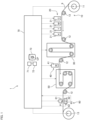
- FIG. 1 is a diagram illustrating a configuration of an inkjet printing apparatus 1 according to a first embodiment of the present invention.
- the inkjet printing apparatus 1 is an apparatus that prints a multicolor image on a surface of the transparent base material 9 having a long band shape by an inkjet method while conveying the transparent base material 9.
- the transparent base material 9 for example, a colorless and transparent resin film is used.
- the transparent base material 9 after printing is cut into a label for a beverage PET bottle, for example.
- the inkjet printing apparatus 1 includes a conveyance mechanism 10, a first printing unit 20, a first drying unit 30, a second printing unit 40, a second drying unit 50, an image acquisition unit 60, and a control unit 70.
- the conveyance mechanism 10 is a mechanism that conveys the transparent base material 9 in the sub scanning direction, which is the longitudinal direction thereof.
- the conveyance mechanism 10 includes an unwinding unit 11, a plurality of conveyance rollers 12, and a winding unit 13.
- the transparent base material 9 is unwound from the unwinding unit 11 and is conveyed along a conveyance path configured by a plurality of conveyance rollers 12.
- Each conveyance roller 12 rotates about a horizontal axis to guide the transparent base material 9 to the downstream side of the conveyance path. Furthermore, the transparent base material 9 after having been conveyed is collected by the winding unit 13.
- the transparent base material 9 moves substantially horizontally at the location under the first printing unit 20 and the second printing unit 40. At this time, the print surface of the transparent base material 9 is faced up.
- the transparent base material 9 is stretched over the plurality of conveyance rollers 12 in a tensioned state. As a result, loosening and a wrinkle of the transparent base material 9 during conveyance are suppressed.
- the first printing unit 20 is a processing unit that ejects so-called process color inks onto the transparent base material 9 conveyed by the conveyance mechanism 10.
- the first printing unit 20 of the present embodiment includes four heads 21.
- the heads 21 eject ink droplets of cyan, magenta, yellow, and black, which are process colors, onto the print surface of the transparent base material 9, respectively.
- Each head 21 is fixed to a housing (not illustrated) of the inkjet printing apparatus 1.
- FIG. 2 is a bottom view of the head 21.
- an ejection surface 210 for ejecting ink droplets is provided on a lower part of the head 21.
- the ejection surface 210 covers the entire width of the transparent base material 9 in the main scanning direction.
- a plurality of nozzles 211 are regularly arranged on the ejection surface 210.
- the plurality of nozzles 211 is arranged so that their positions in the main scanning direction are different from each other.
- ink droplets are ejected from the plurality of nozzles 211 of each head 21 toward the print surface of the transparent base material 9. That is, ink droplets of cyan, magenta, yellow, and black, which are process colors, are ejected from the plurality of nozzles 211 of the heads 21, respectively.
- the four heads 21 print single-color images of cyan, magenta, yellow, and black on the print surface of the transparent base material 9, respectively.
- a multicolor image is formed on the print surface of the transparent base material 9 by superposing these four single-color images.
- the multicolor image printed by the first printing unit 20 is referred to as a "process-color image”.
- the first drying unit 30 is disposed on the downstream side of the first printing unit 20 in the conveyance path.
- the first drying unit 30 dries the process color inks ejected from the four heads 21 of the first printing unit 20.
- the process color inks are fixed on the print surface of the transparent base material 9.
- the first drying unit 30 dries the inks by blowing hot air toward the transparent base material 9 to vaporize a solvent in the inks that adheres to the transparent base material 9.
- the first drying unit 30 may dry or cure the inks by another method such as light emission.
- the second printing unit 40 is disposed downstream of the first drying unit 30 in the conveyance path.
- the second printing unit 40 is a processing unit that ejects an ink of a non-process color different from cyan, magenta, yellow, and black described above onto the transparent base material 9 conveyed by the conveyance mechanism 10.
- the second printing unit 40 of the present embodiment includes one head 41 that ejects ink droplets of white, which is a non-process color.
- the head 41 is fixed to a housing (not illustrated) of the inkjet printing apparatus 1.
- the head 41 of the second printing unit 40 also includes a plurality of nozzles, similarly to the head 21 of the first printing unit 20 described above.
- the head 41 ejects white ink droplets from a plurality of nozzles toward the print surface of the transparent base material 9.
- a white single-color image is printed on the print surface of the transparent base material 9.
- a white single-color image printed by the second printing unit 40 is referred to as a "non process-color image”.
- the second drying unit 50 is disposed downstream of the second printing unit 40 in the conveyance path.
- the second drying unit 50 dries the non process-color ink ejected from the head 41 of the second printing unit 40.
- the non process-color ink is fixed on the print surface of the transparent base material 9.
- the second drying unit 50 dries the ink by blowing heated gas toward the transparent base material 9 to vaporize a solvent in the ink that adheres to the transparent base material 9.
- the second drying unit 50 may dry or cure the ink by another method such as light emission.
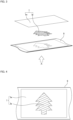
- FIG. 3 is a view conceptually illustrating the relationship among the transparent base material 9, a process-color image Ip, and a non process-color image Iw.
- FIG. 4 is a view of the transparent base material 9 after printing viewed from the non-print surface side (from the direction of arrow A in FIG. 3 ).
- the process-color image Ip is first printed and then the non process-color image Iw is printed on the print surface of the transparent base material 9. Therefore, as illustrated in FIG. 3 , at least part of the process-color image Ip is covered with the non process-color image Iw.
- a printed image I is formed on the print surface of the transparent base material 9 by the process-color image Ip and the non process-color image Iw.
- FIG. 1 is referred to again.
- the image acquisition unit 60 is disposed downstream of the second drying unit 50 in the conveyance path.
- the image acquisition unit 60 captures the printed image I at a predetermined inspection location P on the conveyance path of the transparent base material 9.
- the image acquisition unit 60 includes a first light-emitting unit 61, second light-emitting units 62, and an imaging unit 63.
- the first light-emitting unit 61 is disposed on one side (print-surface side) of the transparent base material 9.
- the second light-emitting units 62 and the imaging unit 63 are disposed on the other side (non print-surface side) of the transparent base material 9.
- the control unit 70 is a means for controlling operation of each unit in the inkjet printing apparatus 1.
- the control unit 70 of the present embodiment is configured by a computer including a processor 71 such as a CPU, a memory 72 such as a RAM, and a storage unit 73 such as a hard disk drive.
- the control unit 70 is communicably connected to the conveyance mechanism 10, the four heads 21 of the first printing unit 20, the first drying unit 30, the head 41 of the second printing unit 40, the second drying unit 50, the first light-emitting unit 61, the second light-emitting units 62, and the imaging unit 63 described above.
- the control unit 70 temporarily reads a computer program CP stored in the storage unit 73 into the memory 72, and the processor 71 performs arithmetic processing based on the computer program CP to control operation of each unit described above.
- the printing process in the inkjet printing apparatus 1 and an inspection process to be described below advance.
- FIG. 5 is a diagram illustrating a configuration of the image acquisition unit 60.
- the image acquisition unit 60 of the present embodiment includes the first light-emitting unit 61, the second light-emitting units 62, and the imaging unit 63.
- the first light-emitting unit 61 is located on one side (print-surface side) of the transparent base material 9 at the inspection location P.
- the first light-emitting unit 61 includes a plurality of light sources 610 arranged in the main scanning direction.
- As the light source 610 for example, an LED (Light Emitting Diode) is used.
- each light source 610 of the first light-emitting unit 61 emits light.
- Light emitted from the first light-emitting unit 61 is preferably white light.
- the second light-emitting units 62 are located on the other side (non print-surface side) of the transparent base material 9 at the inspection location P.
- the second light-emitting units 62 are provided on the upstream side and the downstream side of the imaging unit 63, respectively.
- the second light-emitting units 62 may be installed only on either the upstream side or the downstream side of the imaging unit 63.
- the second light-emitting unit 62 includes a plurality of light sources 620 arranged in the main scanning direction.
- the light source 620 for example, an LED (Light Emitting Diode) is used.
- each light source 620 of the second light-emitting unit 62 emits light. As a result, light is emitted from the second light-emitting unit 62 toward the transparent base material 9. Light emitted from the second light-emitting unit 62 is preferably white light.
- the light amounts of emitted light from the first light-emitting unit 61 and the second light-emitting unit 62 of the present embodiment can be individually changed.
- the light amount is set, for example, by the user inputting a desired value to the control unit 70.
- the imaging unit 63 is located on the other side (non print-surface side) of the transparent base material 9 at the inspection location P. That is, the first light-emitting unit 61 and the imaging unit 63 are located on the opposite sides of the transparent base material 9 with the inspection location P interposed therebetween.
- the imaging unit 63 includes a plurality of imaging elements 630 arranged in the main scanning direction.
- As the imaging element 630 for example, a CCD (Charge-Coupled Device) or a CMOS (Complementary MOS) is used.
- the imaging unit 63 images the transparent base material 9 passing through the inspection location P by using these imaging elements 630. As a result, the image of the transparent base material 9 passing through the inspection location P is obtained as multi-tone digital data.
- an image obtained by the imaging unit 63 is referred to as a "captured image D1".
- the captured image D1 is output from the imaging unit 63 to the control unit 70.
- the control unit 70 includes an inspection processing unit 74.
- the inspection processing unit 74 is a processing unit for inspecting the quality of the printed image I printed on the transparent base material 9 based on the captured image D1 obtained from the imaging unit 63.
- the function of the inspection processing unit 74 is realized by the computer as the control unit 70 operating according to the computer program CP described above.
- the first light-emitting unit 61, the second light-emitting units 62, the imaging unit 63, and the inspection processing unit 74 constitute an inspection device that inspects the printed image I printed on the surface of the transparent base material 9.
- a normal image D2 is stored in advance in the storage unit 73 of the control unit 70.
- the normal image D2 is an image illustrating a state in which the transparent base material 9 is normally printed.
- the normal image D2 is generated in the control unit 70 based on print data.
- the inspection processing unit 74 acquires the captured image D1 from the imaging unit 63 and reads the normal image D2 from the storage unit 73. Then, the captured image D1 and the normal image D2 are compared. As a result, a portion in which the difference between the captured image D1 and the normal image D2 is greater than a preset threshold is detected as a defect.
- Examples of the types of defects include missing of a portion of the printed image I due to clogging of some of the nozzles or the like, misalignment of the printed image I on the print surface of the transparent base material 9, dirt due to unnecessary dropping of ink from the nozzle, and adhesion of foreign matter to the transparent base material 9. Whether or not a character or a code included in the printed image I can be normally identified may also be set as one of the inspection items.
- the normal image D2 used is an image generated based on the print data; however, the normal image D2 is not limited to this.
- a normal image D2 may be generated from an average image of a plurality of captured images D 1, or the like. In this case, it is necessary to confirm that an identical defect does not occur in identical spots; however as compared with a case where the normal image D2 is generated based on the print data, it is possible to suppress the labor of color conversion and resolution conversion and to reduce errors caused by processes of color conversion and resolution conversion.
- the inkjet printing apparatus 1 repeatedly executes steps S1 to S3 in FIG. 6 while executing the printing process on the transparent base material 9.
- the image acquisition unit 60 images the transparent base material 9 passing through the inspection location P (step S1). Specifically, the imaging unit 63 images the transparent base material 9 at the inspection location P while light is emitted toward the transparent base material 9 from the first light-emitting unit 61 and the second light-emitting units 62 described above. As a result, the captured image D1 of the transparent base material 9 at the inspection location P is obtained.
- step S1 of the present embodiment the captured image D1 in which generation of the shadow of the printed image I itself is suppressed is obtained by emitting light from the first light-emitting unit 61. Therefore, in step S2 of the present embodiment, the defect in the printed image I can be accurately inspected based on the obtained captured image D1.
- control unit 70 may automatically reduce the light amount of the first light-emitting unit 61 more as the area ratio of the non process-color image Iw in the printed image I is smaller. Note that the light amount of only one of the first light-emitting unit 61 and the second light-emitting units 62 may be able to be changed.
- FIG. 7 is a diagram illustrating a configuration of an image acquisition unit 60 according to the second embodiment.
- the image acquisition unit 60 of the present embodiment includes a first light-emitting unit 61, second light-emitting units 62, an imaging unit 63, and a background plate 64.
- the background plate 64 is located on one side (print-surface side) of a transparent base material 9 at an inspection location P.
- the background plate 64 has a background surface 640 that extends in parallel to the print surface of the transparent base material 9 and faces the print surface.
- the background surface 640 covers the entire width of the transparent base material 9 in the main scanning direction.
- the color of the background surface 640 of the background plate 64 is a color different from any of the colors of inks ejected from heads 21 of a first printing unit 20 (process colors) and the color of ink ejected from a head 41 of a second printing unit 40 (non-process color).
- the color of the background plate 64 is gray.
- step S1 it is possible to acquire a captured image D1 in which the shadow of the printed image I itself is suppressed by light emitted from the first light-emitting unit 61 and reflected by the background plate 64. Therefore, in step S2 of the present embodiment, the defect in the printed image I can be accurately inspected based on the obtained captured image D1.
- FIG. 8 is a flowchart illustrating an example of a background color determination method.
- a plurality of candidate colors that are candidates for the background color are prepared.
- Each candidate color is a multi-primary color including two or more color components of the plurality of process colors and the non-process color.
- the plurality of process colors, the non-process color, and the plurality of candidate colors are printed on the transparent base material 9 (step S11).
- the process colors, the non-process color, and the plurality of candidate colors that are printed are imaged by the imaging unit 63 (step S12).
- the captured image obtained by the imaging unit 63 is data defined not by CMYK but by RGB. That is, the colors in the captured image are represented by combinations of R (red), G (green), and B (blue) values.
- the RGB values of the plurality of process colors and the non-process color are compared with the RGB values of each candidate color (step S13). Then, the candidate color with largest difference in RGB value from the plurality of process colors and the non-process color is determined as the background color (step S14).
- the background surface 640 of the background plate 64 and the printed image I can be more clearly distinguished in the captured image D1. Therefore, the printed image I can be accurately inspected based on the captured image D1.
- the projection unit 65 is located on one side (print-surface side) of a transparent base material 9.
- the projection unit 65 is directed to the background surface 640 of the background plate 64.
- the projection unit 65 includes a plurality of rows of light sources 650 arranged in the main scanning direction.
- the light sources 650 in each row emit different colors.
- As the light source 650 for example, an LED (Light Emitting Diode) is used.
- the projection unit 65 causes the light sources 650 in any row to emit light in response to a command from the control unit 70. As a result, light in a plurality of colors is selectively emitted from the projection unit 65 toward the background surface 640 of the background plate 64.
- the second light-emitting units 62, the imaging unit 63, and an inspection processing unit 74 are equal to those in the above-described first and second embodiments, and thus overlapping description will be omitted.
- the second light-emitting units 62, the imaging unit 63, the background plate 64, the projection unit 65, and the inspection processing unit 74 constitute an inspection device that inspects a printed image I printed on the surface of the transparent base material 9.
- step S1 imaging is performed with the background plate 64 disposed on one side of the transparent base material 9.
- the projection unit 65 emits light in a predetermined color to the background plate 64.
- light reflected by the background surface 640 of the background plate 64 passes through the transparent base material 9 and is incident on the imaging unit 63.
- step S1 it is possible to acquire a captured image D1 in which the shadow of the printed image I itself is suppressed by light emitted from the projection unit 65 and reflected by the background plate 64. Therefore, in step S2 of the present embodiment, the defect in the printed image I can be accurately inspected based on the obtained captured image D1.
- the captured image D1 obtained in step S1 includes a portion corresponding to the background surface 640 of the background plate 64 and a portion corresponding to the printed image I located in front of the background surface 640.
- the color of the light emitted from the projection unit 65 to the background plate 64 is, for example, a color different from any of the colors of inks ejected from heads 21 of a first printing unit 20 (process colors) and the color of ink ejected from a head 41 of a second printing unit 40 (non-process color). Therefore, in the obtained captured image D1, a process-color image Ip and a non process-color image Iw, and the background surface 640 appear clearly distinguishably. Therefore, the printed image I can be accurately inspected based on the captured image D1.
- the control unit 70 switches the color of light emitted from the projection unit 65 depending on the printed image I.
- the projection unit 65 emits light in a color with the greatest difference in RGB value from the colors included in the printed image I, among the colors of light that can be emitted from the projection unit 65.
- a printed image I having a large proportion of green such as a label for a green tea beverage
- red color in contrast to green is emitted.
- blue such as a label for a sports drink
- blue such as a label for a sports drink
- the second light-emitting units 62 may be omitted in the configuration of the image acquisition unit 60 of the first embodiment.
- the first light-emitting unit 61 may be omitted in the configuration of the image acquisition unit 60 of the second embodiment.
- the second light-emitting unit 62 may be omitted in the configuration of the image acquisition unit 60 of the second embodiment.
- the second light-emitting unit 62 may be omitted in the configuration of the image acquisition unit 60 of the third embodiment.
- light emitted from the first light-emitting unit 61 may be light other than white light.
- the color of light emitted from the first light-emitting unit 61 may be a color different from any of the colors of inks ejected from the heads 21 of the first printing unit 20 (process colors) and the color of ink ejected from the head 41 of the second printing unit 40 (non-process color).
- the color of light emitted from the first light-emitting unit 61 may be switched depending on the printed image I.
- the first printing unit 20 includes the four heads 21.
- the number of heads 21 included in the first printing unit 20 may be one to three, or may be five or more.
- heads 21 that eject inks of spot colors such as purple/violet and green in addition to inks of cyan, magenta, yellow, and black may be provided.
- an inkjet printing apparatus of the present invention may perform printing on each of a plurality of transparent base materials while sequentially conveying the plurality of transparent base materials in the sub scanning direction.
- a first aspect of the invention is an inspection device that inspects a printed image printed on a surface of a transparent base material, the device comprising:
- a second aspect of the invention is the inspection device according to the first aspect, wherein
- a third aspect of the invention is the inspection device according to the second aspect, wherein a light amount of at least one of the first light-emitting unit and the second light-emitting unit is capable of being changed.
- a fourth aspect of the invention is the inspection device according to the third aspect further comprising a control unit configured to reduce the light amount of the first light-emitting unit more as an area ratio of the non process-color image is smaller.
- a fifths aspect of the invention is the inspection device according to any one of the second to fourth aspect, wherein
- a sixth aspect of the invention is an inspection device that inspect a printed image printed on a surface of a transparent base material
- a ninth aspect of the invention is the inspection device according to any one of the sixth to eighth aspect, wherein
- a tenth aspect of the invention is an inspection device that inspects a printed image printed on a surface of a transparent base material, the device comprising:
- An eleventh aspect of the invention is an inkjet printing apparatus including the inspection device according to any one of the first to tenth aspect, the apparatus comprising:
- a twelfth aspect of the invention is an inspection method of inspecting a printed image printed on a surface of a transparent base material, the method comprising:
- a thirteenth aspect of the invention is an inspection method of inspecting a printed image printed on a surface of a transparent base material
- a fourteenth aspect of the invention is an inspection method of inspecting a printed image printed on a surface of a transparent base material, the method comprising:
Landscapes
- Engineering & Computer Science (AREA)
- Physics & Mathematics (AREA)
- Spectroscopy & Molecular Physics (AREA)
- General Physics & Mathematics (AREA)
- Multimedia (AREA)
- Signal Processing (AREA)
- Quality & Reliability (AREA)
- Textile Engineering (AREA)
- General Engineering & Computer Science (AREA)
- Theoretical Computer Science (AREA)
- Ink Jet (AREA)
- Investigating Materials By The Use Of Optical Means Adapted For Particular Applications (AREA)
Applications Claiming Priority (3)
| Application Number | Priority Date | Filing Date | Title |
|---|---|---|---|
| JP2018025585A JP7021972B2 (ja) | 2018-02-16 | 2018-02-16 | 検査装置、インクジェット印刷装置、および検査方法 |
| EP18906032.0A EP3753743B1 (fr) | 2018-02-16 | 2018-12-11 | Dispositif d'inspection, dispositif d'impression par jet d'encre et procédé d'inspection |
| PCT/JP2018/045467 WO2019159516A1 (fr) | 2018-02-16 | 2018-12-11 | Dispositif d'inspection, dispositif d'impression par jet d'encre et procédé d'inspection |
Related Parent Applications (2)
| Application Number | Title | Priority Date | Filing Date |
|---|---|---|---|
| EP18906032.0A Division-Into EP3753743B1 (fr) | 2018-02-16 | 2018-12-11 | Dispositif d'inspection, dispositif d'impression par jet d'encre et procédé d'inspection |
| EP18906032.0A Division EP3753743B1 (fr) | 2018-02-16 | 2018-12-11 | Dispositif d'inspection, dispositif d'impression par jet d'encre et procédé d'inspection |
Publications (2)
| Publication Number | Publication Date |
|---|---|
| EP4513376A2 true EP4513376A2 (fr) | 2025-02-26 |
| EP4513376A3 EP4513376A3 (fr) | 2025-05-07 |
Family
ID=67619884
Family Applications (2)
| Application Number | Title | Priority Date | Filing Date |
|---|---|---|---|
| EP18906032.0A Active EP3753743B1 (fr) | 2018-02-16 | 2018-12-11 | Dispositif d'inspection, dispositif d'impression par jet d'encre et procédé d'inspection |
| EP24221624.0A Pending EP4513376A3 (fr) | 2018-02-16 | 2018-12-11 | Dispositif d'inspection, appareil d'impression à jet d'encre et procédé d'inspection |
Family Applications Before (1)
| Application Number | Title | Priority Date | Filing Date |
|---|---|---|---|
| EP18906032.0A Active EP3753743B1 (fr) | 2018-02-16 | 2018-12-11 | Dispositif d'inspection, dispositif d'impression par jet d'encre et procédé d'inspection |
Country Status (4)
| Country | Link |
|---|---|
| US (1) | US11913838B2 (fr) |
| EP (2) | EP3753743B1 (fr) |
| JP (1) | JP7021972B2 (fr) |
| WO (1) | WO2019159516A1 (fr) |
Families Citing this family (7)
| Publication number | Priority date | Publication date | Assignee | Title |
|---|---|---|---|---|
| CN112020435B (zh) * | 2018-05-16 | 2022-07-08 | 惠普发展公司,有限责任合伙企业 | 确定光源的反射光强度的方法、打印设备和计算机可读介质 |
| JP7418081B2 (ja) * | 2019-10-28 | 2024-01-19 | キヤノン株式会社 | 画像形成装置、画像形成方法、及び、プログラム |
| JP7628753B2 (ja) * | 2019-12-18 | 2025-02-12 | コニカミノルタ株式会社 | 画像検査装置、画像検査方法、プログラム及び画像形成システム |
| JP7476634B2 (ja) * | 2020-04-14 | 2024-05-01 | コニカミノルタ株式会社 | 画像形成装置、画像形成装置の制御方法、および画像形成装置の制御プログラム |
| JP7663330B2 (ja) | 2020-09-18 | 2025-04-16 | 株式会社Screenホールディングス | 印刷装置 |
| JP7604150B2 (ja) | 2020-09-18 | 2024-12-23 | 株式会社Screenホールディングス | 検査装置及びそれを備えたインクジェット印刷装置 |
| US12125195B2 (en) * | 2022-03-04 | 2024-10-22 | Ricoh Company, Ltd. | Inspection system, inspection method, and non-transitory recording medium |
Citations (2)
| Publication number | Priority date | Publication date | Assignee | Title |
|---|---|---|---|---|
| JP2013159047A (ja) | 2012-02-06 | 2013-08-19 | Seiko Epson Corp | 不良ノズル検出装置、不良ノズル検出方法、および、コンピュータープログラム |
| JP6010980B2 (ja) | 2012-04-03 | 2016-10-19 | セイコーエプソン株式会社 | 印刷装置 |
Family Cites Families (33)
| Publication number | Priority date | Publication date | Assignee | Title |
|---|---|---|---|---|
| DD113512A1 (fr) | 1974-08-29 | 1975-06-12 | ||
| US5790186A (en) | 1995-12-27 | 1998-08-04 | Advanced Vision Technology (A.V.T.) Ltd. | Apparatus and method for reducing shade effects during print quality control |
| US6272440B1 (en) * | 1997-12-11 | 2001-08-07 | Metso Paper Automation, Inc. | Method and apparatus for measuring color and/or composition |
| JP2891696B1 (ja) * | 1998-04-23 | 1999-05-17 | 株式会社東京機械製作所 | 印刷画像検査装置 |
| US6347857B1 (en) * | 1999-09-23 | 2002-02-19 | Encad, Inc. | Ink droplet analysis apparatus |
| DE10234084B4 (de) * | 2002-07-26 | 2006-06-14 | Koenig & Bauer Ag | Vorrichtung zur Inspektion von bogenförmigen Material |
| JP2004195722A (ja) * | 2002-12-17 | 2004-07-15 | Fuji Photo Film Co Ltd | キャリブレーション方法およびハードコピー作成装置 |
| JP3801571B2 (ja) * | 2003-02-28 | 2006-07-26 | 三菱重工業株式会社 | カラー印刷物の画像読取装置 |
| JP4823890B2 (ja) * | 2003-03-06 | 2011-11-24 | ディジマーク コーポレイション | ドキュメント認証方法 |
| JP2006047078A (ja) * | 2004-08-04 | 2006-02-16 | Central Glass Co Ltd | 透明板状体の印刷欠陥および/または印刷汚れの検査方法 |
| JP2006093791A (ja) * | 2004-09-21 | 2006-04-06 | Sharp Corp | 画像読取装置および画像形成装置 |
| JP2006110952A (ja) | 2004-10-18 | 2006-04-27 | Canon Inc | 画像形成装置及びその制御方法 |
| JP2006264833A (ja) * | 2005-03-23 | 2006-10-05 | Canon Inc | 記録材判別装置及び画像形成装置 |
| GB2448245B (en) * | 2005-12-23 | 2009-11-04 | Ingenia Holdings | Optical authentication |
| DE602007011013D1 (de) * | 2006-09-27 | 2011-01-20 | Fujifilm Corp | Etikettendrucker und Verfahren zur Etikettenerzeugung |
| JP2008087287A (ja) * | 2006-09-29 | 2008-04-17 | Fujifilm Corp | インク吐出不良検出方法および画像形成装置 |
| JP4964002B2 (ja) * | 2007-03-29 | 2012-06-27 | キヤノン電子株式会社 | 画像読取装置、画像読取装置の制御方法、原稿画像データの色補正方法、画像読取装置の制御プログラム、および原稿画像データの色補正プログラム |
| US20140154808A1 (en) * | 2012-12-03 | 2014-06-05 | Gordhanbhai N. Patel | Monitoring system based on etching of metals |
| AU2009256212B2 (en) * | 2008-06-04 | 2015-12-10 | Jp Laboratories Inc. | A monitoring system based on etching of metals |
| JP5197311B2 (ja) * | 2008-11-11 | 2013-05-15 | キヤノン株式会社 | 記録材判別装置及びそれを用いた画像形成装置 |
| JP5225064B2 (ja) * | 2008-12-26 | 2013-07-03 | 花王株式会社 | 検査装置 |
| JP2011093179A (ja) * | 2009-10-29 | 2011-05-12 | Seiko Epson Corp | インクジェット記録装置のキャリッジ装置およびこれを備えたインクジェット記録装置 |
| JP5783226B2 (ja) * | 2009-11-09 | 2015-09-24 | セイコーエプソン株式会社 | 印刷装置、及び、印刷方法 |
| JP5418377B2 (ja) * | 2009-11-09 | 2014-02-19 | セイコーエプソン株式会社 | 印刷装置、及び、印刷方法 |
| JP2011121311A (ja) * | 2009-12-11 | 2011-06-23 | Seiko Epson Corp | 印刷装置におけるドット抜け検査方法、および印刷装置 |
| US8810810B2 (en) * | 2010-09-22 | 2014-08-19 | Komori Corporation | Printing quality inspection apparatus |
| JP2012153088A (ja) * | 2011-01-28 | 2012-08-16 | Seiko Epson Corp | 印刷装置および印刷方法 |
| CN105415888B (zh) * | 2011-11-25 | 2017-06-06 | 精工爱普生株式会社 | 液体排出检查装置及液体排出检查方法 |
| JP2014113692A (ja) * | 2012-12-06 | 2014-06-26 | Seiko Epson Corp | 吐出検査方法、吐出検査装置、及び液滴吐出装置 |
| JP6337541B2 (ja) * | 2014-03-18 | 2018-06-06 | 株式会社リコー | 画像検査装置、画像形成システム及び画像検査方法 |
| JP6432877B2 (ja) * | 2014-10-24 | 2018-12-05 | 富士ゼロックス株式会社 | 印刷検品システム |
| US10124618B2 (en) * | 2016-02-12 | 2018-11-13 | Ricoh Company, Ltd. | Inspection apparatus and method of inspection |
| WO2017196301A1 (fr) * | 2016-05-10 | 2017-11-16 | Hewlett-Packard Development Company, L.P. | Impression à l'aide d'un spectrophotomètre |
-
2018
- 2018-02-16 JP JP2018025585A patent/JP7021972B2/ja active Active
- 2018-12-11 EP EP18906032.0A patent/EP3753743B1/fr active Active
- 2018-12-11 WO PCT/JP2018/045467 patent/WO2019159516A1/fr not_active Ceased
- 2018-12-11 EP EP24221624.0A patent/EP4513376A3/fr active Pending
- 2018-12-11 US US16/967,372 patent/US11913838B2/en active Active
Patent Citations (2)
| Publication number | Priority date | Publication date | Assignee | Title |
|---|---|---|---|---|
| JP2013159047A (ja) | 2012-02-06 | 2013-08-19 | Seiko Epson Corp | 不良ノズル検出装置、不良ノズル検出方法、および、コンピュータープログラム |
| JP6010980B2 (ja) | 2012-04-03 | 2016-10-19 | セイコーエプソン株式会社 | 印刷装置 |
Also Published As
| Publication number | Publication date |
|---|---|
| EP3753743B1 (fr) | 2025-02-12 |
| EP4513376A3 (fr) | 2025-05-07 |
| WO2019159516A1 (fr) | 2019-08-22 |
| JP7021972B2 (ja) | 2022-02-17 |
| US20210033463A1 (en) | 2021-02-04 |
| US11913838B2 (en) | 2024-02-27 |
| EP3753743A4 (fr) | 2022-03-09 |
| EP3753743A1 (fr) | 2020-12-23 |
| JP2019142007A (ja) | 2019-08-29 |
Similar Documents
| Publication | Publication Date | Title |
|---|---|---|
| US11913838B2 (en) | Inspection device, inkjet printing apparatus, and inspection method | |
| US10105948B2 (en) | Image inspection device, image inspection method, program, and ink jet printing system | |
| JP6565331B2 (ja) | ノズル検査装置および画像形成装置 | |
| US9387711B2 (en) | Image recording apparatus and method | |
| JP6053244B2 (ja) | プリントヘッドの検査方法、プリント方法、プリントヘッドの検査装置及びプリンタ | |
| US7052102B2 (en) | Detecting fixer in hardcopy apparatus | |
| JP2013208838A (ja) | 印刷物検査方法および印刷物検査装置並びにインクジェット印刷装置 | |
| JP2013193300A (ja) | 画像形成方法、画像形成装置およびプログラム | |
| JP5699051B2 (ja) | 画像検査装置および画像記録装置、並びに、画像検査方法 | |
| US20230278329A1 (en) | Printing system and defective nozzle detection method | |
| JP7126477B2 (ja) | 画像検査方法及び装置、プログラム並びに画像記録システム | |
| JP6171723B2 (ja) | 液体吐出装置 | |
| US10232634B2 (en) | Inkjet recording apparatus | |
| JP6379908B2 (ja) | ノズル検査装置、画像形成装置およびノズル検査方法 | |
| JP5286924B2 (ja) | 画像形成装置、画像形成方法、画像補正方法、画像形成プログラム、及び画像補正プログラム | |
| JP5129539B2 (ja) | 記録不良検出装置、画像記録装置及び記録不良検出方法 | |
| US10265975B2 (en) | Inkjet recording apparatus | |
| JP7468129B2 (ja) | テスト画像データ生成装置、インクジェット記録装置及びテスト画像データ生成方法 | |
| JP2015150765A (ja) | インクジェット記録ヘッドの混色検査方法および記録装置 | |
| US12555223B2 (en) | Printed material inspection device, printed material inspection method, program, and printing system | |
| JP2021133594A (ja) | 画像記録装置、異常検出制御方法及びプログラム | |
| US20250050656A1 (en) | Printing device inline inspection system and methods | |
| JP2010111031A (ja) | 印刷検査装置及び印刷検査方法 | |
| JP2022107858A (ja) | 画像検品装置、画像形成システム及びプログラム |
Legal Events
| Date | Code | Title | Description |
|---|---|---|---|
| PUAI | Public reference made under article 153(3) epc to a published international application that has entered the european phase |
Free format text: ORIGINAL CODE: 0009012 |
|
| STAA | Information on the status of an ep patent application or granted ep patent |
Free format text: STATUS: THE APPLICATION HAS BEEN PUBLISHED |
|
| AC | Divisional application: reference to earlier application |
Ref document number: 3753743 Country of ref document: EP Kind code of ref document: P |
|
| AK | Designated contracting states |
Kind code of ref document: A2 Designated state(s): AL AT BE BG CH CY CZ DE DK EE ES FI FR GB GR HR HU IE IS IT LI LT LU LV MC MK MT NL NO PL PT RO RS SE SI SK SM TR |
|
| REG | Reference to a national code |
Ref country code: DE Ref legal event code: R079 Free format text: PREVIOUS MAIN CLASS: G06K0015020000 Ipc: B41J0029393000 |
|
| PUAL | Search report despatched |
Free format text: ORIGINAL CODE: 0009013 |
|
| AK | Designated contracting states |
Kind code of ref document: A3 Designated state(s): AL AT BE BG CH CY CZ DE DK EE ES FI FR GB GR HR HU IE IS IT LI LT LU LV MC MK MT NL NO PL PT RO RS SE SI SK SM TR |
|
| RIC1 | Information provided on ipc code assigned before grant |
Ipc: G06T 1/00 20060101ALI20250331BHEP Ipc: G01N 21/00 20060101ALI20250331BHEP Ipc: G01J 3/50 20060101ALI20250331BHEP Ipc: G01J 3/46 20060101ALI20250331BHEP Ipc: G06K 15/02 20060101ALI20250331BHEP Ipc: B41J 15/04 20060101ALI20250331BHEP Ipc: B41J 2/165 20060101ALI20250331BHEP Ipc: B41J 2/21 20060101ALI20250331BHEP Ipc: B41J 2/01 20060101ALI20250331BHEP Ipc: B41J 29/393 20060101AFI20250331BHEP |
|
| STAA | Information on the status of an ep patent application or granted ep patent |
Free format text: STATUS: REQUEST FOR EXAMINATION WAS MADE |
|
| 17P | Request for examination filed |
Effective date: 20251107 |