EP4513428A1 - Verfahren, vorrichtung und system zum testen einer kathodenelektrodenfolie eines verbundstreifens - Google Patents
Verfahren, vorrichtung und system zum testen einer kathodenelektrodenfolie eines verbundstreifens Download PDFInfo
- Publication number
- EP4513428A1 EP4513428A1 EP23790899.1A EP23790899A EP4513428A1 EP 4513428 A1 EP4513428 A1 EP 4513428A1 EP 23790899 A EP23790899 A EP 23790899A EP 4513428 A1 EP4513428 A1 EP 4513428A1
- Authority
- EP
- European Patent Office
- Prior art keywords
- electrode plate
- region
- plate body
- body region
- composite material
- Prior art date
- Legal status (The legal status is an assumption and is not a legal conclusion. Google has not performed a legal analysis and makes no representation as to the accuracy of the status listed.)
- Pending
Links
Images



Classifications
-
- G—PHYSICS
- G01—MEASURING; TESTING
- G01N—INVESTIGATING OR ANALYSING MATERIALS BY DETERMINING THEIR CHEMICAL OR PHYSICAL PROPERTIES
- G01N21/00—Investigating or analysing materials by the use of optical means, i.e. using sub-millimetre waves, infrared, visible or ultraviolet light
- G01N21/84—Systems specially adapted for particular applications
- G01N21/88—Investigating the presence of flaws or contamination
-
- G—PHYSICS
- G01—MEASURING; TESTING
- G01N—INVESTIGATING OR ANALYSING MATERIALS BY DETERMINING THEIR CHEMICAL OR PHYSICAL PROPERTIES
- G01N21/00—Investigating or analysing materials by the use of optical means, i.e. using sub-millimetre waves, infrared, visible or ultraviolet light
- G01N21/84—Systems specially adapted for particular applications
- G01N21/88—Investigating the presence of flaws or contamination
- G01N21/8851—Scan or image signal processing specially adapted therefor, e.g. for scan signal adjustment, for detecting different kinds of defects, for compensating for structures, markings, edges
-
- G—PHYSICS
- G01—MEASURING; TESTING
- G01N—INVESTIGATING OR ANALYSING MATERIALS BY DETERMINING THEIR CHEMICAL OR PHYSICAL PROPERTIES
- G01N21/00—Investigating or analysing materials by the use of optical means, i.e. using sub-millimetre waves, infrared, visible or ultraviolet light
- G01N21/84—Systems specially adapted for particular applications
- G01N21/88—Investigating the presence of flaws or contamination
- G01N21/89—Investigating the presence of flaws or contamination in moving material, e.g. running paper or textiles
- G01N21/8914—Investigating the presence of flaws or contamination in moving material, e.g. running paper or textiles characterised by the material examined
-
- G—PHYSICS
- G01—MEASURING; TESTING
- G01N—INVESTIGATING OR ANALYSING MATERIALS BY DETERMINING THEIR CHEMICAL OR PHYSICAL PROPERTIES
- G01N21/00—Investigating or analysing materials by the use of optical means, i.e. using sub-millimetre waves, infrared, visible or ultraviolet light
- G01N21/84—Systems specially adapted for particular applications
- G01N21/88—Investigating the presence of flaws or contamination
- G01N21/89—Investigating the presence of flaws or contamination in moving material, e.g. running paper or textiles
- G01N21/892—Investigating the presence of flaws or contamination in moving material, e.g. running paper or textiles characterised by the flaw, defect or object feature examined
-
- G—PHYSICS
- G06—COMPUTING OR CALCULATING; COUNTING
- G06T—IMAGE DATA PROCESSING OR GENERATION, IN GENERAL
- G06T7/00—Image analysis
-
- G—PHYSICS
- G06—COMPUTING OR CALCULATING; COUNTING
- G06T—IMAGE DATA PROCESSING OR GENERATION, IN GENERAL
- G06T7/00—Image analysis
- G06T7/0002—Inspection of images, e.g. flaw detection
- G06T7/0004—Industrial image inspection
-
- G—PHYSICS
- G06—COMPUTING OR CALCULATING; COUNTING
- G06T—IMAGE DATA PROCESSING OR GENERATION, IN GENERAL
- G06T7/00—Image analysis
- G06T7/0002—Inspection of images, e.g. flaw detection
- G06T7/0004—Industrial image inspection
- G06T7/001—Industrial image inspection using an image reference approach
-
- G—PHYSICS
- G06—COMPUTING OR CALCULATING; COUNTING
- G06T—IMAGE DATA PROCESSING OR GENERATION, IN GENERAL
- G06T7/00—Image analysis
- G06T7/10—Segmentation; Edge detection
- G06T7/11—Region-based segmentation
-
- G—PHYSICS
- G06—COMPUTING OR CALCULATING; COUNTING
- G06T—IMAGE DATA PROCESSING OR GENERATION, IN GENERAL
- G06T7/00—Image analysis
- G06T7/10—Segmentation; Edge detection
- G06T7/13—Edge detection
-
- G—PHYSICS
- G06—COMPUTING OR CALCULATING; COUNTING
- G06V—IMAGE OR VIDEO RECOGNITION OR UNDERSTANDING
- G06V10/00—Arrangements for image or video recognition or understanding
- G06V10/20—Image preprocessing
- G06V10/22—Image preprocessing by selection of a specific region containing or referencing a pattern; Locating or processing of specific regions to guide the detection or recognition
-
- H—ELECTRICITY
- H01—ELECTRIC ELEMENTS
- H01M—PROCESSES OR MEANS, e.g. BATTERIES, FOR THE DIRECT CONVERSION OF CHEMICAL ENERGY INTO ELECTRICAL ENERGY
- H01M10/00—Secondary cells; Manufacture thereof
- H01M10/05—Accumulators with non-aqueous electrolyte
- H01M10/058—Construction or manufacture
- H01M10/0583—Construction or manufacture of accumulators with folded construction elements except wound ones, i.e. folded positive or negative electrodes or separators, e.g. with "Z"-shaped electrodes or separators
-
- H—ELECTRICITY
- H01—ELECTRIC ELEMENTS
- H01M—PROCESSES OR MEANS, e.g. BATTERIES, FOR THE DIRECT CONVERSION OF CHEMICAL ENERGY INTO ELECTRICAL ENERGY
- H01M10/00—Secondary cells; Manufacture thereof
- H01M10/06—Lead-acid accumulators
- H01M10/12—Construction or manufacture
- H01M10/125—Cells or batteries with wound or folded electrodes
-
- G—PHYSICS
- G01—MEASURING; TESTING
- G01N—INVESTIGATING OR ANALYSING MATERIALS BY DETERMINING THEIR CHEMICAL OR PHYSICAL PROPERTIES
- G01N21/00—Investigating or analysing materials by the use of optical means, i.e. using sub-millimetre waves, infrared, visible or ultraviolet light
- G01N21/84—Systems specially adapted for particular applications
- G01N2021/8472—Investigation of composite materials
-
- G—PHYSICS
- G06—COMPUTING OR CALCULATING; COUNTING
- G06T—IMAGE DATA PROCESSING OR GENERATION, IN GENERAL
- G06T2207/00—Indexing scheme for image analysis or image enhancement
- G06T2207/30—Subject of image; Context of image processing
- G06T2207/30108—Industrial image inspection
- G06T2207/30164—Workpiece; Machine component
-
- Y—GENERAL TAGGING OF NEW TECHNOLOGICAL DEVELOPMENTS; GENERAL TAGGING OF CROSS-SECTIONAL TECHNOLOGIES SPANNING OVER SEVERAL SECTIONS OF THE IPC; TECHNICAL SUBJECTS COVERED BY FORMER USPC CROSS-REFERENCE ART COLLECTIONS [XRACs] AND DIGESTS
- Y02—TECHNOLOGIES OR APPLICATIONS FOR MITIGATION OR ADAPTATION AGAINST CLIMATE CHANGE
- Y02E—REDUCTION OF GREENHOUSE GAS [GHG] EMISSIONS, RELATED TO ENERGY GENERATION, TRANSMISSION OR DISTRIBUTION
- Y02E60/00—Enabling technologies; Technologies with a potential or indirect contribution to GHG emissions mitigation
- Y02E60/10—Energy storage using batteries
-
- Y—GENERAL TAGGING OF NEW TECHNOLOGICAL DEVELOPMENTS; GENERAL TAGGING OF CROSS-SECTIONAL TECHNOLOGIES SPANNING OVER SEVERAL SECTIONS OF THE IPC; TECHNICAL SUBJECTS COVERED BY FORMER USPC CROSS-REFERENCE ART COLLECTIONS [XRACs] AND DIGESTS
- Y02—TECHNOLOGIES OR APPLICATIONS FOR MITIGATION OR ADAPTATION AGAINST CLIMATE CHANGE
- Y02P—CLIMATE CHANGE MITIGATION TECHNOLOGIES IN THE PRODUCTION OR PROCESSING OF GOODS
- Y02P70/00—Climate change mitigation technologies in the production process for final industrial or consumer products
- Y02P70/50—Manufacturing or production processes characterised by the final manufactured product
Definitions
- This application relates to the field of battery technologies, in particular, to the field of battery production inspection technologies, and specifically, to a method, apparatus, and system for inspecting a cathode electrode plate of a composite material tape, an electronic device, a laminator, a computer-readable storage medium, and a computer program product.
- a rechargeable battery may include a plurality of battery cells connected in series and/or in parallel.
- the battery cell is the smallest unit that provides an energy source in the battery.
- a cell assembly is a key component in which electrochemical reactions occur in a battery cell, and its main structure includes an anode electrode plate, a cathode electrode plate, and a separator separating the anode electrode plate from the cathode electrode plate.
- cell assemblies may be divided into laminated cell assemblies and wound cell assemblies. Compared with a wound cell assembly, a laminated cell assembly has the characteristics of high capacity, low internal resistance, and adaptivity to more shape designs, so the application scenarios are more extensive.
- a lamination process of the laminated cell assembly is mainly carried out in a laminator.
- This application is intended to solve at least one of the technical problems existing in some cases. Therefore, one objective of this application is to provide a method, apparatus, and system for inspecting a cathode electrode plate of a composite material tape, an electronic device, a laminator, a computer-readable storage medium, and a computer program product.
- An embodiment of a first aspect of this application provides a method for inspecting a cathode electrode plate of a composite material tape.
- the method includes: using a camera apparatus to photograph a composite material tape being transported on a laminator to obtain an inspection image covering the composite material tape, where the inspection image includes an electrode plate body region; extracting the electrode plate body region from the inspection image; and inspecting the electrode plate body region to determine a metal leakage defect existing in the electrode plate body region.
- an inspection can be performed on a composite material tape being transported on a laminator, so that whether a metal leakage defect exists on a cathode electrode plate can be detected in real time in the production process of a laminated cell assembly.
- the efficiency of detecting the metal leakage defect of the cathode electrode plate is improved; and in addition, timely detection of the metal leakage defect in the production process of the laminated cell assembly can also reduce material waste in subsequent production processes.
- the inspecting the electrode plate body region to determine a metal leakage defect existing in the electrode plate body region includes: inspecting based on a pixel value of the electrode plate body region.
- a pixel value in the inspection image is easy to obtain and calculate, therefore, a metal leakage inspection can be carried out efficiently on the electrode plate body region based on the pixel value of the electrode plate body region.
- a metal leakage region exists in the electrode plate body region, a pixel value of the metal leakage region will have a certain deviation compared with the pixel value of another normal region.
- performing metal leakage inspection based on the pixel value of each electrode plate body region can improve the accuracy of metal leakage inspection.
- the inspecting based on a pixel value of the electrode plate body region includes: determining whether the electrode plate body region includes at least one suspected defect region, and a pixel value of any pixel in each suspected defect region is within a first pixel value range; and in response to determining that the electrode plate body region includes at least one suspected defect region and that the at least one suspected defect region meets a preset condition, determining that a metal leakage defect exists in the electrode plate body region.
- a suspected defect region it means that an area of the metal leakage region may be larger than an area required by the process. Determining that metal leakage exists in a suspected defect region only when the region meets the preset condition can not only accurately detect a metal leakage region that does not meet the process requirements, but also avoid false detection, thus further improving the inspection efficiency of metal leakage.
- the preset condition includes: an area of any one of the suspected defect regions is greater than a preset threshold.
- a preset threshold for example, the leakage metal area threshold required by the process
- the determining whether the electrode plate body region includes at least one suspected defect region includes: in the electrode plate body region, obtaining a plurality of abnormal pixels with pixel values within the first pixel value range; and dividing the plurality of abnormal pixels so that adjacent pixels in the plurality of abnormal pixels are located in at least one suspected defect region which is independently connected.
- the camera apparatus is a line-scan camera
- the inspection image is a continuously scanned image of the composite material tape being transported on the laminator.
- the extracting the electrode plate body region from the inspection image includes: intercepting at least one image slice from the inspection image; and extracting the electrode plate body region from the image slice.
- a line-scan camera is more applicable to a situation where there is relative motion between an object being inspected and the camera, and a higher resolution and a larger field of view can be obtained, thus further improving the accuracy of metal leakage inspection.
- the inspection image further includes a separator region surrounding the electrode plate body region, a backup roller region at least partially surrounding the separator region, and a plurality of tab regions located at two sides of the separator region, where the extracting the electrode plate body region from the inspection image includes: at least based on pixel values of a plurality of pixels included in the inspection image, extracting the electrode plate body region from the inspection image.
- Pixel values of the pixels corresponding to the backup roller region, the plurality of tab regions, and the electrode plate body region in the inspection image are different, therefore, at least based on the pixel values of these regions, removing the backup roller region and the plurality of tab regions contained in the inspection image can extract the electrode plate body region quickly and accurately, and reduce interference of the backup roller region and the plurality of tab regions on the metal leakage inspection, thereby further improving the accuracy of metal leakage inspection.
- the at least based on pixel values of a plurality of pixels included in the inspection image, extracting the electrode plate body region from the inspection image includes: based on a first pixel threshold corresponding to the backup roller region, removing the backup roller region from the inspection image to obtain a first intermediate image; extracting, from the first intermediate image, an image of a largest rectangular region inscribed with an edge thereof, as a second intermediate image to remove the plurality of tab regions; and based on a second pixel threshold corresponding to the electrode plate body region, extracting the electrode plate body region from the second intermediate image.
- the backup roller region and the plurality of tab regions can be gradually removed, and in addition, the manner of removing the plurality of tab regions is more accurate. This further improves the accuracy of extracting the electrode plate body region and the accuracy of metal leakage inspection.
- the using a camera apparatus to photograph a composite material tape being transported on a laminator to obtain an inspection image covering the composite material tape includes: using the camera apparatus to photograph each side of the composite material tape being transported on the laminator to obtain the inspection image covering the composite material tape.
- metal leakage inspection can be carried out on each side of the composite material tape.
- the method for inspecting a cathode electrode plate of a composite material tape further includes: in response to determining that a metal leakage defect exists in the electrode plate body region, outputting an inspection result, where the inspection result includes at least one of position information of the electrode plate body region in the composite material tape and an area of the electrode plate body region.
- An embodiment of a second aspect of this application provides an apparatus for inspecting a cathode electrode plate of a composite material tape.
- the apparatus includes: an image acquisition unit, configured to use a camera apparatus to photograph a composite material tape being transported on a laminator to obtain an inspection image covering the composite material tape, where the inspection image includes an electrode plate body region; a region extraction unit, configured to extract the electrode plate body region from the inspection image; and a metal leakage inspection unit, configured to inspect the electrode plate body region to determine a metal leakage defect existing in the electrode plate body region.
- An embodiment of a third aspect of this application provides an electronic device including at least one processor and a memory communicatively connected to the at least one processor, where the memory stores instructions that are executable by the at least one processor, and the instructions are executed by the at least one processor to enable the at least one processor to perform the method for inspecting a cathode electrode plate of a composite material tape according to the foregoing aspect.
- An embodiment of a fourth aspect of this application provides a system for inspecting a cathode electrode plate of a composite material tape.
- the system includes: at least one camera apparatus, configured to photograph the composite material tape being transported on a laminator; and the electronic device according to the foregoing aspect.
- metal leakage inspection can be performed on a composite material tape being transported on a laminator, so that whether a metal leakage defect exists on a cathode electrode plate can be detected in real time in the production process of a laminated cell assembly.
- This improves the efficiency of detecting the metal leakage defect of the electrode plate; and in addition, timely detection of the metal leakage defect in the production process of the laminated cell assembly can also reduce material waste in subsequent production processes.
- the at least one camera apparatus includes a first line-scan camera configured to photograph a first side surface of the composite material tape and a second line-scan camera configured to photograph a second side surface of the composite material tape opposite the first side surface.
- the system further includes a first line light source for providing illumination to an image acquisition region of the first line-scan camera and a second line light source for providing illumination to an image acquisition region of the second line-scan camera.
- a line-scan camera is more applicable to a situation where there is relative motion between an object being inspected and the camera, and a higher resolution and a larger field of view can be obtained.
- a line light source is configured to provide illumination for the line-scan camera.
- the system for inspecting a cathode electrode plate of a composite material tape further includes: a first backup roller, where the first backup roller is configured to abut against the second side surface of the composite material tape in the image acquisition region of the first line-scan camera; a first encoder connected to the first backup roller, where the first encoder is configured to send a pulse signal to the first line-scan camera along with the progressing of the composite material tape on the first backup roller, so as to trigger the first line-scan camera to photograph the first side surface of the composite material tape line by line; a second backup roller, where the second backup roller is configured to abut against the first side surface of the composite material tape in the image acquisition region of the second line-scan camera; and a second encoder connected to the second backup roller, where the second encoder is configured to send a pulse signal to the second line-scan camera along with the progressing of the composite material tape on the second backup roller, so as to trigger the second line-scan camera to photograph the second side surface of the composite material
- An embodiment of a fifth aspect of this application provides a laminator including the system according to the foregoing aspect.
- a metal leakage defect of the composite material tape can be detected, which is beneficial for adjusting the related components of the laminator in time.
- An embodiment of a sixth aspect of this application provides a computer-readable storage medium storing computer instructions, where the computer instructions are configured to enable a computer to perform the method for inspecting a cathode electrode plate of a composite material tape according to the foregoing aspect.
- An embodiment of a seventh aspect of this application provides a computer program product including a computer program, where when the computer program is executed by a processor, the method for inspecting a cathode electrode plate of a composite material tape according to the foregoing aspect is implemented.
- a metal leakage defect of the composite material tape can be detected in the lamination process, which is beneficial for adjusting the related components of the laminator in time. This can effectively control the flow-out of cell assemblies with a metal leakage defect in the separator and reduce material waste during production.
- the term "and/or" is only an associative relationship for describing associated objects, indicating that three relationships may be present.
- a and/or B may indicate the following three cases: presence of only A, presence of both A and B, and presence of only B.
- the character "/" in this specification generally indicates an "or" relationship between contextually associated objects.
- a plurality of means more than two (inclusive).
- a plurality of groups means more than two (inclusive) groups
- a plurality of pieces means more than two (inclusive) pieces.
- the terms “mounting”, “connection”, “join”, and “fastening” should be understood in their general senses. For example, they may refer to a fixed connection, a detachable connection, or an integral connection, may refer to a mechanical connection or electrical connection, and may refer to a direct connection, an indirect connection via an intermediate medium, an internal communication between two elements, or an interaction between two elements. Persons of ordinary skill in the art can understand specific meanings of these terms in this application as appropriate to specific situations.
- a laminated cell assembly 100 includes a plurality of anode electrode plates 110 and a plurality of cathode electrode plates 120 alternately arranged, and a separator 130 arranged between any adjacent anode electrode plate 110 and cathode electrode plate 120.
- the anode electrode plate 110 includes an anode electrode plate body 111 provided with an active substance and an anode tab 112 not provided with an active substance layer
- the cathode electrode plate 120 includes a cathode electrode plate body 121 provided with an active substance and a cathode tab 122 not provided with an active substance layer.
- the laminated cell assembly 100 is infiltrated by an electrolyte. Lithium ions move between the anode and cathode of the battery cell with the electrolyte as a medium, so that the battery cell can be charged and discharged.
- the function of the separator 130 is to allow lithium ions to pass freely while preventing the passage of electrons, thereby preventing a short circuit between the anode and cathode of the battery cell through the electrolyte.
- the laminator 200 includes a first cutting mechanism 210, a first thermal compounding mechanism 220, two second cutting mechanisms 230, a second thermal compounding mechanism 240, and a laminating mechanism 250 which are arranged in sequence.
- the first cutting mechanism 210 is configured to cut out a first electrode plate material segment from a first electrode plate material tape.
- the first thermal compounding mechanism 220 is configured to thermally compound a first separator and a second separator with two side surfaces of the first electrode plate material segment to form a primary composite material tape.
- the two second cutting mechanisms 230 are configured to cut out a second electrode plate and a third electrode plate from a second electrode plate material tape and a third electrode plate material tape respectively.
- the second electrode plate material tape and the third electrode plate material tape have a same polarity (they can be made of a same material and have a same structure), which is opposite a polarity of the first electrode plate material tape.
- the second thermal compounding mechanism 240 is configured to alternately thermally compound the second electrode plate and the third electrode plate with two side surfaces of the primary composite material tape to form a secondary composite material tape (hereinafter referred to as a composite material tape for short, and its cross-sectional structure is, for example, shown in FIG. 3 ).
- the laminating mechanism 250 is configured to laminate and cut the composite material tape to form a laminated assembly.
- the laminating mechanism 250 of the laminator 200 folds a unit to be cut in a zigzag folding mode and cuts it to obtain a laminated assembly. After that, subsequent production processes for the cell assembly can be carried out, such as thermal compression and tab welding.
- an X-ray imager is used to scan around the laminated cell assembly, and then whether a defect exists in an electrode plate of the laminated cell assembly is determined according to a scanned image.
- the working principle of the X-ray imager is that: when X-rays irradiate a sample, their transmission intensity depends not only on the energy of the X-rays but also on the material density and thickness of the sample. A lower material density and a smaller thickness allow the X-rays to pass through the sample more easily.
- the transmission intensity of the X-rays is imaged by using an image receiving and converting apparatus based on brightness and darkness contrast of grayscale, thus forming an X-ray scanned image.
- the applicant after in-depth research, has provided a method, apparatus, and system for inspecting a cathode electrode plate of a composite material tape, an electronic device, a laminator, a computer-readable storage medium, and a computer program product.
- This solution can implement real-time and accurate inspection of whether a metal leakage defect exists on the cathode electrode plates during the production process of laminated cell assemblies, thereby improving the production yield rate of laminated cell assemblies.
- the solution in embodiments of this application utilizes computer vision technology.
- a camera apparatus is used to photograph a composite material tape being transported on a laminator to obtain an inspection image covering the composite material tape, where the inspection image includes an electrode plate body region; then, the electrode plate body region is extracted from the inspection image; and subsequently, the electrode plate body region is inspected to determine a metal leakage defect existing in the electrode plate body region.
- a metal leakage inspection can be performed on a composite material tape being transported on a laminator, so that whether a metal leakage defect exists on a cathode electrode plate can be detected in real time in the production process of a laminated cell assembly.
- this improves the efficiency of detecting the metal leakage defect of the electrode plate; and in addition, timely detection of the metal leakage defect in the production process of the laminated cell assembly can also reduce material waste in subsequent production processes.
- FIG. 3 shows a system 300 for inspecting a cathode electrode plate of a composite material tape according to some embodiments of this application.
- the main hardware configuration of the system 300 includes at least one camera apparatus (for example, a first camera apparatus 310 and a second camera apparatus 320) and an electronic device 390.
- the electronic device 390 is connected to each of the at least one camera apparatus, and is configured to inspect a composite material tape based on image information collected by the camera apparatus (a specific inspection method will be described below).
- the first camera apparatus 310 is configured to collect image information on one side surface of the composite material tape
- the second camera apparatus 320 is configured to collect image information on another side surface of the composite material tape.
- the electronic device 390 is connected to each of the first camera apparatus 310 and the second camera apparatus 320, and is configured to inspect two side surfaces of the composite material tape based on the image information collected by the first camera apparatus 310 or the second camera apparatus 320.
- the electronic device 390 may communicate with the first camera apparatus 310 and the second camera apparatus 320 through wired connection or wireless connection. Since a main target of image acquisition performed by the first camera apparatus 310 and the second camera apparatus 320 is the composite material tape, the first camera apparatus 310 and the second camera apparatus 320 may be arranged at an appropriate position between the second thermal compounding mechanism and the laminating mechanism of the laminator.
- the specific types of the first camera apparatus 310 and the second camera apparatus 320 are not limited, and a conventional area-scan industrial camera or a line-scan camera may be used.
- the at least one camera apparatus includes a first line-scan camera configured to photograph a first side surface of the composite material tape and a second line-scan camera configured to photograph a second side surface of the composite material tape opposite the first side surface.
- the system 300 for inspecting the cathode electrode plate of the composite material tape may further include a first line light source 330 for providing illumination to an acquisition region of the first line-scan camera and a second line light source 340 for providing illumination to an acquisition region of the second line-scan camera.
- a line-scan camera also referred to as a line-array camera, is applicable to a situation where there is relative motion between an object being inspected and the camera, and a higher resolution and a larger field of view can be obtained.
- capturing line by line image information on a moving object being inspected can obtain an infinitely extended continuous image.
- an image slice can be intercepted from the continuous image.
- the electronic device can then perform real-time processing on the image slice or store the image slice in a cache for later processing.
- the first line light source 330 and the second line light source 340 are configured to provide illumination for their respective corresponding line-scan cameras. Taking the first line light source 330 and the first line-scan camera as an example, their relative installation positions should meet the following requirement: the first line light source 330 focuses on the composite material tape to form a narrow bright strip which should be parallel to a sensor of the first line-scan camera. This allows the line-scan camera to obtain better image quality.
- the specific types of the first line light source 330 and the second line light source 340 are not limited, and may be, for example, an LED light source, a halogen lamp, or a high-frequency fluorescent lamp.
- the system 300 for inspecting a cathode electrode plate of a composite material tape further includes: a first backup roller 350, a first encoder 370 connected to the first backup roller 350, a second backup roller 360, and a second encoder 380 connected to the second backup roller 360.
- the first backup roller 350 is configured to abut against the second side surface of the composite material tape in the image acquisition region of the first line-scan camera.
- the first encoder 370 is configured to send a pulse signal to the first line-scan camera along with the progressing of the composite material tape on the first backup roller 350, so as to trigger the first line-scan camera to photograph the first side surface of the composite material tape line by line.
- the second backup roller 360 is configured to abut against the first side surface of the composite material tape in the image acquisition region of the second line-scan camera.
- the second encoder 380 is configured to send a pulse signal to the second line-scan camera along with the progressing of the composite material tape on the second backup roller, so as to trigger the second line-scan camera to photograph the second side surface of the composite material tape line by line.
- the encoder can convert a rotation angle into a pulse signal.
- the first encoder 370 emits a pulse signal, triggering the first line-scan camera to scan one line on a side surface of the composite material tape.
- the first backup roller 350 and the second backup roller 360 can tighten the composite material tape, which is beneficial for accurately capturing an image of the composite material tape, thus further improving the accuracy of metal leakage defect inspection.
- the image slice 400 may further include a backup roller region 440 corresponding to the first backup roller 350 and the second backup roller 360.
- each image slice 400 may include a separator region 410, an electrode plate body region 420 surrounded by the separator region 410, and a plurality of tab regions 430 protruding from the separator region 410.
- the image slice 400 may also include an image of another object except for the composite material tape, such as an image of a backup roller, corresponding to the backup roller region 440 in the image slice 400.
- the electrode plate body region 420 may be a body region of a cathode electrode plate exposed on the composite material tape, and a body region of an anode electrode plate is not visible in the image slice 400 because the anode electrode plate is sandwiched between two separators, but the tab region 430 of the anode electrode plate protruding out of the separator region 410 is visible.
- the image slice 400 may further include a tab and separator overlapping region 4100 connected between the electrode plate body region 420 and the tab region 430, and the entirety of the tab and separator overlapping region 4100 and the tab region 430 corresponds to a tab of an exposed electrode plate on the composite material tape, that is, the entirety of the electrode plate body region 420, the tab and separator overlapping region 4100, and the tab region 430 corresponds to an exposed electrode plate on the composite material tape.
- a tab of an electrode plate is not provided with an active substance layer, and a portion of the electrode plate corresponding to the tab region 430 exposes a current collector of a metal material, and a portion of the electrode plate corresponding to the tab and separator overlapping region 4100 can expose the current collector of the metal material or be provided with a light-colored insulating layer.
- a grayscale of the current collector of the metal material or the light-colored insulating layer in the image slice 400 will not be lower than the grayscale of the separator region 410. Therefore, in some embodiments of this application, to simplify the calculation, the tab and separator overlapping region 4100 may be included in the separator region 410, so that the separator region 410 includes the tab and separator overlapping region 4100.
- FIG. 5 is a schematic flowchart of a method 500 for inspecting an electrode plate of a composite material tape according to some embodiments of this application. As shown in FIG. 5 , the method 500 includes steps S501 to S503.
- step S501 a camera apparatus is used to photograph a composite material tape being transported on a laminator to obtain an inspection image covering the composite material tape, where the inspection image includes an electrode plate body region.
- step S502 the electrode plate body region is extracted from the inspection image.
- step S503 the electrode plate body region is inspected to determine a metal leakage defect existing in the electrode plate body region.
- the camera apparatus may be an industrial camera or a machine vision camera, for example, the camera apparatus may be an area-scan CCD industrial camera with a high frame rate to obtain a clear inspection image.
- the camera apparatus may alternatively be the line-scan camera described above.
- the inspection image covering the composite material tape obtained by capturing using a camera apparatus may be an inspection image as shown on the right side of FIG. 4 .
- a cathode electrode plate body region 420 may be extracted from the inspection image, so that inspection can be performed in the body region 420 to determine whether metal leakage exists in the cathode electrode plate body region (for example, in the example of FIG. 6 , the body region 420 may include a region 460c where a metal leakage region exists).
- a corner detection algorithm of computer vision may be used to detect corners of the inspection image obtained in step S501, and in response to detecting corresponding corners at preset positions (for example, positions corresponding to four corners of the region 420), a region surrounded by these corners is determined as the body region 420.
- the inspection of the cathode electrode plate body region 420 may be to input an image of the cathode electrode plate body region 420 into a pre-trained neural network model to obtain a metal leakage inspection result predicted by the neural network model.
- Training samples of the neural network model may include samples without metal leakage defects and samples with metal leakage defects.
- the composite material tape being transported on the laminator can be inspected, so that whether there is a metal leakage defect on the cathode electrode plate can be detected in real time in the production process of a laminated cell assembly.
- this improves the efficiency of detecting the metal leakage defect of the electrode plate; and in addition, timely detection of the metal leakage defect in the production process of the laminated cell assembly can also reduce material waste in subsequent production processes.
- the foregoing step S503 may include: inspecting based on a pixel value of the electrode plate body region.
- a pixel value in the inspection image is easy to obtain and calculate, therefore, an inspection can be carried out efficiently on the electrode plate body region based on the pixel value of the electrode plate body region.
- a metal leakage region exists in the electrode plate body region (that is, when the active substance layer of some parts of the cathode electrode plate body region falls off)
- the pixel value of the metal leakage region will have a certain deviation compared with the pixel value of another normal region (that is, a region in the electrode plate body region where the active substance layer does not fall off).
- performing metal leakage inspection based on the pixel value of the electrode plate body region can improve the accuracy of metal leakage inspection.
- this region will expose a current collector of metal material, and the pixel value of the metal leakage region is smaller than a pixel value of a surrounding normal region. Comparing the pixel values of the two regions can identify a region where metal leakage may exist.
- the inspecting based on a pixel value of the electrode plate body region includes: determining whether the electrode plate body region includes at least one suspected defect region, and a pixel value of any pixel in each suspected defect region is within a first pixel value range; and in response to determining that the electrode plate body region includes at least one suspected defect region and that the at least one suspected defect region meets a preset condition, determining that a metal leakage defect exists in the electrode plate body region.
- At least one suspected defect region (for example, three suspected defect regions 460a, 460b, and 460c shown in FIG. 6 ) may be determined first.
- a pixel value of any pixel in each suspected defect region may be within a first pixel value range.
- metal leakage may exist in the three suspected defect regions.
- at least one suspected defect region such as the suspected defect region 460c
- a preset condition for example, the pixel value of the suspected defect region is less than a preset threshold
- the suspected defect regions 460a and 460b may not meet the above preset condition, the suspected defect regions 460a and 460b may not be determined as metal leakage regions.
- a suspected defect region When a suspected defect region is detected, it means that an area of the metal leakage region may be larger than an area required by the process. Determining that metal leakage exists in a suspected defect region only when the region meets the preset condition can not only accurately detect a metal leakage region that does not meet the process requirements, but also avoid false detection, thus further improving the inspection efficiency of metal leakage.
- the preset condition includes: an area of any one of the suspected defect regions is greater than a preset threshold.
- an area of the detected suspected defect region is greater than the preset threshold (for example, a leakage metal area threshold required by the process), it means that the area of the metal leakage region does not meet the process requirements.
- the preset threshold for example, a leakage metal area threshold required by the process
- the suspected defect region 460c occupies an area of 3 square millimeters (mm 2 ), and the preset threshold may be an area of 2 mm 2
- the preset threshold may be an area of 2 mm 2
- metal leakage exists in the electrode plate body region (that is, the suspected defect region 460c is a metal leakage region).
- the areas occupied by the other two suspected defect regions 460a and 460b are both smaller than the preset threshold (the area of 2 mm 2 )
- the suspected defect regions 460a and 460b are not determined as metal leakage regions.
- the method of comparing the areas of the foregoing suspected defect regions with the preset threshold has a higher accuracy in metal leakage defect detection when compared with the method of using an X-ray imager to scan around a laminated cell assembly in the related art.
- the preset condition is not limited to the above one.
- an image of the electrode plate body region may also be input into a trained neural network model, and a confidence level output by the neural network model for representing at least one suspected defect region being a defect region (that is, a metal leakage region) is obtained.
- the foregoing preset condition may be that the confidence level is greater than a preset confidence level.
- the determining whether the electrode plate body region includes at least one suspected defect region includes:
- a plurality of abnormal pixel points with pixel values within the first pixel value range can be obtained.
- the plurality of abnormal pixels are divided based on a connection operator (connection operator) of machine vision software, so that adjacent pixels among the plurality of abnormal pixels whose pixel values are within the first pixel value range are located in at least one suspected defect region (the suspected defect region 460c and two regions below the suspected defect region 460c) which is independently connected.
- a plurality of non-adjacent abnormal pixels are divided to form their own connected domains.
- an area_center operator (region center operator) of the machine vision software a connected domain with an area larger than an area threshold can be screened out (for example, a connected domain with an area larger than 2 mm 2 can be screened out).
- the cathode electrode plate body region 420 can be binarized first, and then the above operations can be performed on the binarized electrode plate body region image, thus making the calculation process simpler.
- the camera apparatus is a line-scan camera
- the inspection image is a continuously scanned image of the composite material tape being transported on the laminator.
- step S502 of extracting the electrode plate body region from the inspection image may further include:
- image slices can be intercepted from a continuous image photographed by a line-scan camera, so as to obtain the inspection image.
- the specific type of the image slicing algorithm is not limited, for example, it may be a threshold-based slicing algorithm, a region-based slicing algorithm, an edge-based slicing algorithm, or a specific theory-based slicing algorithm. Referring to FIG. 4 , in some embodiments of this application, a threshold-based slicing method is adopted.
- edges of the cathode electrode plate body region 420 along a width direction of the composite material tape are found. Then, based on two adjacent edges of the cathode electrode plate body region 420 along the width direction of the composite material tape, the continuous image 450 is divided along the width direction of the composite material tape (a dividing line can avoid the cathode electrode plate body region 420 and be separated by several rows of pixels from the cathode electrode plate body region 420), to obtain an image slice 400.
- the image slice 400 is the inspection image.
- a line-scan camera is more applicable to a situation where there is relative motion between an object being inspected and the camera, and a higher resolution and a larger field of view can be obtained, thus further improving the accuracy of metal leakage inspection.
- the inspection image may further include a separator region surrounding the electrode plate body region, a backup roller region at least partially surrounding the separator region, and a plurality of tab regions located at two sides of the separator region.
- step S502 of extracting the electrode plate body region from the inspection image may further include: at least based on pixel values of a plurality of pixels included in the inspection image, extracting the electrode plate body region from the inspection image.
- Pixel values of the pixels corresponding to the backup roller region, the plurality of tab regions, and the electrode plate body region in the inspection image are different, therefore, at least based on the pixel values of these regions, removing the backup roller region and the plurality of tab regions contained in the inspection image can extract the electrode plate body region quickly and accurately, and reduce interference of the backup roller region and the plurality of tab regions on the metal leakage inspection, thereby further improving the accuracy of metal leakage inspection.
- a plurality of pixel threshold ranges a, b, c, and d can be set.
- the pixel values of the electrode plate body region, the separator region, the backup roller region, and the tab region can fall into a corresponding pixel value range of each of the foregoing pixel threshold ranges (for example, the pixel value of the electrode plate body region falls into the above range a).
- a region where a pixel value falls within the above range a can be extracted as the electrode plate body region.
- the at least based on pixel values of a plurality of pixels included in the inspection image, extracting the electrode plate body region from the inspection image includes the following steps.
- Step S702 Extract, from the first intermediate image, an image of a largest rectangular region inscribed with an edge thereof, as a second intermediate image to remove the plurality of tab regions.
- Step S703 Based on a second pixel threshold corresponding to the electrode plate body region, extract the electrode plate body region from the second intermediate image.
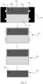
- FIG. 8 is another schematic diagram of inspection on a cathode electrode plate of a composite material tape according to some embodiments of this application.
- the grayscale G1 of the tab region 430, the grayscale G2 of the separator region 410, the grayscale G3 of the cathode electrode plate body region, and the grayscale G4 of the backup roller region 440 satisfy G4 ⁇ G3 ⁇ G2 ⁇ G1. Therefore, based on the first pixel threshold (for example, set to 15) corresponding to the backup roller region 440, two backup roller regions 440 can be removed from the image slice 400 (that is, the inspection image) to obtain a first intermediate image 810.
- the first pixel threshold for example, set to 15
- the grayscale differences between the backup roller region 440 and other regions are used in combination with the Blob algorithm to remove two backup roller regions 440 from the image slice 400, that is, feature regions with grayscale less than or equal to the maximum grayscale threshold of the backup roller region 440 are removed.
- Blob refers to a connected region in an image
- Blob analysis is to extract and mark a connected domain of a binary image obtained after foreground/background separation.
- the core idea of the Blob algorithm is to identify, in a region, a range where "grayscale mutation" occurs so as to determine its size, shape, and area.
- the maximum grayscale threshold of the foregoing backup roller region 440 may be used as the grayscale threshold for binarizing the image slice 400.
- step S701 first, based on the first pixel threshold (for example, set to 15) corresponding to the backup roller region 440, the image slice 400 is binarized, from which a feature region with a grayscale less than or equal to the first pixel threshold corresponding to the backup roller region 440 is extracted; then, based on a connection operator (connection operator) of the machine vision software, the feature region is divided so that the non-adjacent regions are divided to form their own connected domains; subsequently, based on a select_shape operator (filter operator) of the machine vision software, connected domains (corresponding to the two backup roller regions 440) with areas larger than a preset area threshold are screened out; and then, based on a difference operator (subtraction operator) of the machine vision software, the two backup roller regions 440 are removed from the image slice 400 to obtain the first intermediate image 810.
- connection operator connection operator
- step S702 based on an inner_rectangle1 operator (inscribed rectangle operator) of the machine vision software, the largest inscribed rectangle inscribed with edges of the first intermediate image 810 is calculated. A region of the largest inscribed rectangle (that is, the largest rectangular region) is then intercepted as a second intermediate image 820, thereby the plurality of tab regions 430 are removed.
- an inner_rectangle1 operator inscribed rectangle operator
- the second intermediate image 820 is binarized, from which a feature region with a grayscale less than or equal to the second pixel threshold (for example, set to 25) corresponding to the foregoing cathode electrode plate body region 420 is extracted; then, based on a opening_rectangle1 operator (opening operation operator) of the machine vision software, opening operation is performed on the feature region to remove noise; subsequently, based on a connection operator (connection operator) of the machine vision software, the feature region is divided so that non-adjacent regions are divided to form their own connected domains; and then, based on a select_shape operator (filter operator) of the machine vision software, a connected domain with a largest area and a rectangle degree greater than a rectangle degree threshold (for example, the rectangle degree is in a range of 0 to 1, and the rectangle degree threshold is set to 0.8) is screened out, which is the cathode electrode plate body region 420.
- a select_shape operator filter operator
- the backup roller region and the plurality of tab regions can be gradually removed, and in addition, the manner of removing the plurality of tab regions is more accurate. This further improves the accuracy of extracting the electrode plate body region and the accuracy of metal leakage inspection.
- step S501 of using a camera apparatus to photograph a composite material tape being transported on a laminator to obtain an inspection image covering the composite material tape may include: using the camera apparatus to photograph each side of the composite material tape being transported on the laminator to obtain the inspection image covering the composite material tape.
- metal leakage inspection can be carried out on each side of the composite material tape.
- the position information of the electrode plate body region in the composite material tape may be, for example, the photographing code corresponding to the image slice.
- the alarm information may be sound, light, or a combination of sound and light.
- this is beneficial for timely understanding the situations, such as location and area, of the metal leakage region in the composite material tape, which can assist in analyzing the causes of metal leakage and making timely adjustments to the relevant components of the laminator.
- an embodiment of this application further provides an apparatus 900 for detecting a defect of an electrode plate of a composite material tape.
- the apparatus includes:
- the composite material tape being transported on the laminator can be inspected, so that whether there is metal leakage defect on the cathode electrode plate can be detected in real time in the production process of a laminated cell assembly.
- this improves the efficiency of detecting the metal leakage defect of the electrode plate; and in addition, timely detection of the metal leakage defect in the production process of the laminated cell assembly can also reduce material waste in subsequent production processes.
- An embodiment of this application further provides an electronic device including at least one processor and a memory communicatively connected to the at least one processor, where the memory stores instructions that can be executed by the at least one processor, and the instructions are executed by the at least one processor to enable the at least one processor to perform the foregoing method for inspecting a cathode electrode plate of a composite material tape.
- the foregoing electronic device of the embodiments of this application can perform an inspection on a composite material tape being transported on a laminator, so that whether a metal leakage defect exists on a cathode electrode plate can be detected in real time in the production process of a laminated cell assembly.
- this improves the efficiency of detecting the metal leakage defect of the electrode plate; and in addition, timely detection of the metal leakage defect in the production process of the laminated cell assembly can also reduce material waste in subsequent production processes.
- an embodiment of this application further provides a laminator 1000 including the foregoing system 300 for inspecting an electrode plate of a composite material tape.
- the laminator 1000 includes a first cutting mechanism 1010, a first thermal compounding mechanism 1020, two second cutting mechanisms 1030, a second thermal compounding mechanism 1040, and a laminating mechanism 1050 which are arranged in sequence.
- the system 300 for inspecting an electrode plate of a composite material tape is arranged between the second thermal compounding mechanism 1040 and the laminating mechanism 1050.
- the first cutting mechanism 1010 is configured to cut out a first electrode plate material segment from a first electrode plate material tape.
- the first thermal compounding mechanism 1020 is configured to thermally compound a first separator and a second separator with two side surfaces of the first electrode plate material segment to form a primary composite material tape.
- the two second cutting mechanisms 1030 are configured to cut out a second electrode plate and a third electrode plate from a second electrode plate material tape and a third electrode plate material tape respectively.
- the second electrode plate material tape and the third electrode plate material tape have a same polarity, which is opposite a polarity of the first electrode plate material tape.
- the second thermal compounding mechanism 1040 is configured to alternately thermally compound the second electrode plate and the third electrode plate with two side surfaces of the primary composite material tape to form a secondary composite material tape.
- the laminating mechanism 1050 is configured to laminate and cut the composite material tape to form a laminated assembly.
- a metal leakage defect existing in the cathode electrode plate of the composite material tape can be detected, which is beneficial for relevant personnel to adjust the related components of the laminator in time. This can effectively control the flow-out of cell assemblies with a defect in the separator, as well as reduce material waste during production.
- An embodiment of this application further provides a computer-readable storage medium storing computer instructions, where the computer instructions are configured to enable a computer to perform the method for inspecting a cathode electrode plate of a composite material tape according to any one of the foregoing embodiment of this application.
- An embodiment of this application further provides a computer program product including a computer program, where when the computer program is executed by a processor, the method for inspecting a cathode electrode plate of a composite material tape according to any one of the foregoing embodiments is implemented.
Landscapes
- Engineering & Computer Science (AREA)
- General Physics & Mathematics (AREA)
- Physics & Mathematics (AREA)
- Theoretical Computer Science (AREA)
- Computer Vision & Pattern Recognition (AREA)
- Chemical & Material Sciences (AREA)
- Immunology (AREA)
- Health & Medical Sciences (AREA)
- General Health & Medical Sciences (AREA)
- Analytical Chemistry (AREA)
- Life Sciences & Earth Sciences (AREA)
- Pathology (AREA)
- Biochemistry (AREA)
- Manufacturing & Machinery (AREA)
- Chemical Kinetics & Catalysis (AREA)
- General Chemical & Material Sciences (AREA)
- Quality & Reliability (AREA)
- Electrochemistry (AREA)
- Textile Engineering (AREA)
- Signal Processing (AREA)
- Multimedia (AREA)
- Investigating Materials By The Use Of Optical Means Adapted For Particular Applications (AREA)
Applications Claiming Priority (2)
| Application Number | Priority Date | Filing Date | Title |
|---|---|---|---|
| CN202210405673.XA CN115841445B (zh) | 2022-04-18 | 2022-04-18 | 对复合料带的阴极极片进行检测的方法、装置和系统 |
| PCT/CN2023/079378 WO2023202236A1 (zh) | 2022-04-18 | 2023-03-02 | 对复合料带的阴极极片进行检测的方法、装置和系统 |
Publications (2)
| Publication Number | Publication Date |
|---|---|
| EP4513428A1 true EP4513428A1 (de) | 2025-02-26 |
| EP4513428A4 EP4513428A4 (de) | 2025-08-13 |
Family
ID=85574684
Family Applications (1)
| Application Number | Title | Priority Date | Filing Date |
|---|---|---|---|
| EP23790899.1A Pending EP4513428A4 (de) | 2022-04-18 | 2023-03-02 | Verfahren, vorrichtung und system zum testen einer kathodenelektrodenfolie eines verbundstreifens |
Country Status (5)
| Country | Link |
|---|---|
| US (1) | US20250035560A1 (de) |
| EP (1) | EP4513428A4 (de) |
| KR (1) | KR20250002453A (de) |
| CN (1) | CN115841445B (de) |
| WO (1) | WO2023202236A1 (de) |
Families Citing this family (10)
| Publication number | Priority date | Publication date | Assignee | Title |
|---|---|---|---|---|
| CN116342593B (zh) * | 2023-05-25 | 2023-10-27 | 江苏时代新能源科技有限公司 | 极片的检测方法、装置、设备及介质 |
| CN119309523A (zh) * | 2023-07-14 | 2025-01-14 | 宁德时代新能源科技股份有限公司 | 数据测量的方法、装置和计算机可读存储介质 |
| CN116609493B (zh) * | 2023-07-21 | 2023-09-22 | 宁德时代新能源科技股份有限公司 | 压痕检测方法、叠片电芯制造方法、装置和电子设备 |
| CN116879173B (zh) * | 2023-09-08 | 2024-02-02 | 宁德时代新能源科技股份有限公司 | 阴极片检测系统及方法 |
| CN117800144B (zh) * | 2024-02-08 | 2025-10-21 | 宁德时代新能源科技股份有限公司 | 料带的检测方法、料带的分切方法和模切机 |
| CN117849058B (zh) * | 2024-03-06 | 2024-07-26 | 宁德时代新能源科技股份有限公司 | 用于极片的检测系统和检测方法 |
| CN117871538A (zh) * | 2024-03-07 | 2024-04-12 | 江苏时代新能源科技有限公司 | 缺陷检测系统、缺陷检测方法及相关设备 |
| CN117929280B (zh) * | 2024-03-21 | 2024-09-06 | 宁德时代新能源科技股份有限公司 | 电池蓝膜包覆系统及电池蓝膜包覆的检测方法 |
| CN118209561B (zh) * | 2024-05-21 | 2024-11-15 | 宁德时代新能源科技股份有限公司 | 卷料的检测方法和系统 |
| CN119780093A (zh) * | 2024-11-05 | 2025-04-08 | 比亚迪股份有限公司 | 金属异物检测系统、方法、装置、设备及存储介质 |
Family Cites Families (14)
| Publication number | Priority date | Publication date | Assignee | Title |
|---|---|---|---|---|
| JP6475666B2 (ja) * | 2016-06-01 | 2019-02-27 | フロンティアシステム株式会社 | 欠陥検査装置 |
| CN109613000B (zh) * | 2018-10-30 | 2023-02-03 | 广州超音速自动化科技股份有限公司 | 锂电池涂布缺陷检测方法、系统、设备及存储介质 |
| CN109598721B (zh) * | 2018-12-10 | 2021-08-31 | 广州市易鸿智能装备有限公司 | 电池极片的缺陷检测方法、装置、检测设备和存储介质 |
| CN109741323A (zh) * | 2019-01-09 | 2019-05-10 | 广州市顶丰自动化设备有限公司 | 锂电池的极片检测方法、装置、计算机设备和存储介质 |
| CN109886918A (zh) * | 2019-01-14 | 2019-06-14 | 广州量子激光智能装备有限公司 | 锂电池极片的拉丝毛刺检测方法、电子设备及存储介质 |
| CN110031474B (zh) * | 2019-04-28 | 2022-07-22 | 无锡先导智能装备股份有限公司 | 异物检测方法及异物检测装置 |
| CN111768348B (zh) * | 2020-05-29 | 2022-02-08 | 合肥联宝信息技术有限公司 | 一种缺陷检测方法、设备及计算机可读存储介质 |
| CN111650210B (zh) * | 2020-06-11 | 2021-10-22 | 深圳市信宇人科技股份有限公司 | 高速高精度锂离子电池极片的毛刺检测方法及检测系统 |
| CN112241699B (zh) * | 2020-10-13 | 2024-07-05 | 无锡先导智能装备股份有限公司 | 物体缺陷类别识别方法、装置、计算机设备和存储介质 |
| CN113030093B (zh) * | 2020-12-30 | 2022-07-22 | 凌云光技术股份有限公司 | 一种电池隔膜表面缺陷检测方法和系统 |
| CN113610774B (zh) * | 2021-07-16 | 2024-01-09 | 广州大学 | 一种玻璃划痕缺陷检测方法、系统、装置及存储介质 |
| CN113592845B (zh) * | 2021-08-10 | 2024-11-29 | 深圳市华汉伟业科技有限公司 | 一种电池涂布的缺陷检测方法及装置、存储介质 |
| CN113538430B (zh) * | 2021-09-16 | 2021-12-21 | 深圳新视智科技术有限公司 | 基于差分的极片缺陷检测方法、装置、设备及介质 |
| CN114359176B (zh) * | 2021-12-16 | 2024-07-09 | 苏州镁伽科技有限公司 | 面板检测方法、装置、电子设备及存储介质 |
-
2022
- 2022-04-18 CN CN202210405673.XA patent/CN115841445B/zh active Active
-
2023
- 2023-03-02 WO PCT/CN2023/079378 patent/WO2023202236A1/zh not_active Ceased
- 2023-03-02 EP EP23790899.1A patent/EP4513428A4/de active Pending
- 2023-03-02 KR KR1020247037561A patent/KR20250002453A/ko active Pending
-
2024
- 2024-10-17 US US18/919,047 patent/US20250035560A1/en active Pending
Also Published As
| Publication number | Publication date |
|---|---|
| EP4513428A4 (de) | 2025-08-13 |
| CN115841445A (zh) | 2023-03-24 |
| WO2023202236A1 (zh) | 2023-10-26 |
| US20250035560A1 (en) | 2025-01-30 |
| KR20250002453A (ko) | 2025-01-07 |
| CN115841445B (zh) | 2024-05-17 |
Similar Documents
| Publication | Publication Date | Title |
|---|---|---|
| EP4513428A1 (de) | Verfahren, vorrichtung und system zum testen einer kathodenelektrodenfolie eines verbundstreifens | |
| US20250035559A1 (en) | Method, apparatus, and system for defect detection of cathode electrode plate of composite material strip | |
| US20250061561A1 (en) | Method, apparatus, and system for corner fold detection on cathode electrode plate of composite material strip | |
| US20250037263A1 (en) | Method, apparatus, and system for defect detection of separator of composite material strip | |
| KR102236815B1 (ko) | 이차전지 전극 탭의 누락 및 접힘 결함 검출장치 | |
| KR102926757B1 (ko) | 전지셀의 외관 검사 시스템 | |
| CN114581446B (zh) | 一种叠片电池的电芯异常检测方法及系统 | |
| KR20240050461A (ko) | 배터리 전극 시트 절연 코팅층 결함의 검출 방법, 장치 및 컴퓨터 장치 | |
| JP4595500B2 (ja) | 巻回装置および巻きずれ検査方法 | |
| EP4382858B1 (de) | Spaltmessvorrichtung und spaltmessverfahren | |
| KR20170022346A (ko) | Pcb 결함 및 결함종류 분류 시스템 및 방법 | |
| WO2024139006A1 (zh) | 图像采集装置和极片缺陷检测系统 | |
| US20250290864A1 (en) | Tab defect detection method and tab defect detection device for battery cell | |
| EP4421479A1 (de) | Bildsammelvorrichtung und system zur erkennung von fehlern auf elektrodenblättern | |
| US20240296544A1 (en) | Displacement detection method and apparatus, delivery apparatus, and storage medium | |
| WO2023224222A1 (ko) | 광간섭 단층촬영 기반 이차전지 정렬상태 검사 방법 및 시스템 | |
| JP2013200157A (ja) | 端面検査方法および端面検査装置 | |
| JP4680404B2 (ja) | 電池の極板群検査方法及び装置 | |
| KR20250166131A (ko) | 배터리셀 탭의 검사 장치 및 배터리셀 생산설비 | |
| CN111833309A (zh) | 一种光伏电池片检测方法及装置 | |
| KR102920584B1 (ko) | 전극 탭과 전극 리드의 용접 검사장치 및 방법 | |
| KR102953920B1 (ko) | 전지셀 검사 시스템 및 전지셀 검사 방법 | |
| KR20220087027A (ko) | 전지셀 검사 시스템 및 전지셀 검사 방법 | |
| CN120101637A (zh) | 极片检测方法及系统 |
Legal Events
| Date | Code | Title | Description |
|---|---|---|---|
| STAA | Information on the status of an ep patent application or granted ep patent |
Free format text: STATUS: THE INTERNATIONAL PUBLICATION HAS BEEN MADE |
|
| PUAI | Public reference made under article 153(3) epc to a published international application that has entered the european phase |
Free format text: ORIGINAL CODE: 0009012 |
|
| STAA | Information on the status of an ep patent application or granted ep patent |
Free format text: STATUS: REQUEST FOR EXAMINATION WAS MADE |
|
| 17P | Request for examination filed |
Effective date: 20241113 |
|
| AK | Designated contracting states |
Kind code of ref document: A1 Designated state(s): AL AT BE BG CH CY CZ DE DK EE ES FI FR GB GR HR HU IE IS IT LI LT LU LV MC ME MK MT NL NO PL PT RO RS SE SI SK SM TR |
|
| DAV | Request for validation of the european patent (deleted) | ||
| DAX | Request for extension of the european patent (deleted) | ||
| A4 | Supplementary search report drawn up and despatched |
Effective date: 20250710 |
|
| RIC1 | Information provided on ipc code assigned before grant |
Ipc: G06T 7/00 20170101AFI20250704BHEP Ipc: G01N 21/89 20060101ALI20250704BHEP Ipc: G01N 21/88 20060101ALI20250704BHEP Ipc: G01N 21/892 20060101ALI20250704BHEP Ipc: G06T 7/11 20170101ALI20250704BHEP Ipc: G06T 7/13 20170101ALI20250704BHEP Ipc: G06V 10/22 20220101ALI20250704BHEP Ipc: H01M 10/0583 20100101ALI20250704BHEP Ipc: H01M 10/12 20060101ALI20250704BHEP Ipc: G01N 21/84 20060101ALI20250704BHEP |