EP4513583A1 - Électrode, batterie secondaire la comprenant, et son procédé de fabrication - Google Patents
Électrode, batterie secondaire la comprenant, et son procédé de fabrication Download PDFInfo
- Publication number
- EP4513583A1 EP4513583A1 EP23792221.6A EP23792221A EP4513583A1 EP 4513583 A1 EP4513583 A1 EP 4513583A1 EP 23792221 A EP23792221 A EP 23792221A EP 4513583 A1 EP4513583 A1 EP 4513583A1
- Authority
- EP
- European Patent Office
- Prior art keywords
- electrode
- binder
- film
- mixture
- active material
- Prior art date
- Legal status (The legal status is an assumption and is not a legal conclusion. Google has not performed a legal analysis and makes no representation as to the accuracy of the status listed.)
- Pending
Links
Images

Classifications
-
- H—ELECTRICITY
- H01—ELECTRIC ELEMENTS
- H01M—PROCESSES OR MEANS, e.g. BATTERIES, FOR THE DIRECT CONVERSION OF CHEMICAL ENERGY INTO ELECTRICAL ENERGY
- H01M4/00—Electrodes
- H01M4/02—Electrodes composed of, or comprising, active material
- H01M4/62—Selection of inactive substances as ingredients for active masses, e.g. binders, fillers
- H01M4/621—Binders
- H01M4/622—Binders being polymers
- H01M4/623—Binders being polymers fluorinated polymers
-
- H—ELECTRICITY
- H01—ELECTRIC ELEMENTS
- H01M—PROCESSES OR MEANS, e.g. BATTERIES, FOR THE DIRECT CONVERSION OF CHEMICAL ENERGY INTO ELECTRICAL ENERGY
- H01M4/00—Electrodes
- H01M4/02—Electrodes composed of, or comprising, active material
- H01M4/13—Electrodes for accumulators with non-aqueous electrolyte, e.g. for lithium-accumulators; Processes of manufacture thereof
-
- G—PHYSICS
- G01—MEASURING; TESTING
- G01N—INVESTIGATING OR ANALYSING MATERIALS BY DETERMINING THEIR CHEMICAL OR PHYSICAL PROPERTIES
- G01N3/00—Investigating strength properties of solid materials by application of mechanical stress
- G01N3/20—Investigating strength properties of solid materials by application of mechanical stress by applying steady bending forces
-
- G—PHYSICS
- G01—MEASURING; TESTING
- G01N—INVESTIGATING OR ANALYSING MATERIALS BY DETERMINING THEIR CHEMICAL OR PHYSICAL PROPERTIES
- G01N3/00—Investigating strength properties of solid materials by application of mechanical stress
- G01N3/32—Investigating strength properties of solid materials by application of mechanical stress by applying repeated or pulsating forces
- G01N3/34—Investigating strength properties of solid materials by application of mechanical stress by applying repeated or pulsating forces generated by mechanical means, e.g. hammer blows
-
- H—ELECTRICITY
- H01—ELECTRIC ELEMENTS
- H01M—PROCESSES OR MEANS, e.g. BATTERIES, FOR THE DIRECT CONVERSION OF CHEMICAL ENERGY INTO ELECTRICAL ENERGY
- H01M10/00—Secondary cells; Manufacture thereof
- H01M10/05—Accumulators with non-aqueous electrolyte
- H01M10/052—Li-accumulators
-
- H—ELECTRICITY
- H01—ELECTRIC ELEMENTS
- H01M—PROCESSES OR MEANS, e.g. BATTERIES, FOR THE DIRECT CONVERSION OF CHEMICAL ENERGY INTO ELECTRICAL ENERGY
- H01M4/00—Electrodes
- H01M4/02—Electrodes composed of, or comprising, active material
- H01M4/04—Processes of manufacture in general
- H01M4/0402—Methods of deposition of the material
- H01M4/0404—Methods of deposition of the material by coating on electrode collectors
-
- H—ELECTRICITY
- H01—ELECTRIC ELEMENTS
- H01M—PROCESSES OR MEANS, e.g. BATTERIES, FOR THE DIRECT CONVERSION OF CHEMICAL ENERGY INTO ELECTRICAL ENERGY
- H01M4/00—Electrodes
- H01M4/02—Electrodes composed of, or comprising, active material
- H01M4/04—Processes of manufacture in general
- H01M4/043—Processes of manufacture in general involving compressing or compaction
- H01M4/0435—Rolling or calendering
-
- H—ELECTRICITY
- H01—ELECTRIC ELEMENTS
- H01M—PROCESSES OR MEANS, e.g. BATTERIES, FOR THE DIRECT CONVERSION OF CHEMICAL ENERGY INTO ELECTRICAL ENERGY
- H01M4/00—Electrodes
- H01M4/02—Electrodes composed of, or comprising, active material
- H01M4/13—Electrodes for accumulators with non-aqueous electrolyte, e.g. for lithium-accumulators; Processes of manufacture thereof
- H01M4/139—Processes of manufacture
-
- H—ELECTRICITY
- H01—ELECTRIC ELEMENTS
- H01M—PROCESSES OR MEANS, e.g. BATTERIES, FOR THE DIRECT CONVERSION OF CHEMICAL ENERGY INTO ELECTRICAL ENERGY
- H01M4/00—Electrodes
- H01M4/02—Electrodes composed of, or comprising, active material
- H01M4/62—Selection of inactive substances as ingredients for active masses, e.g. binders, fillers
- H01M4/624—Electric conductive fillers
- H01M4/625—Carbon or graphite
-
- H—ELECTRICITY
- H01—ELECTRIC ELEMENTS
- H01M—PROCESSES OR MEANS, e.g. BATTERIES, FOR THE DIRECT CONVERSION OF CHEMICAL ENERGY INTO ELECTRICAL ENERGY
- H01M4/00—Electrodes
- H01M4/02—Electrodes composed of, or comprising, active material
- H01M4/64—Carriers or collectors
- H01M4/66—Selection of materials
- H01M4/661—Metal or alloys, e.g. alloy coatings
-
- H—ELECTRICITY
- H01—ELECTRIC ELEMENTS
- H01M—PROCESSES OR MEANS, e.g. BATTERIES, FOR THE DIRECT CONVERSION OF CHEMICAL ENERGY INTO ELECTRICAL ENERGY
- H01M4/00—Electrodes
- H01M4/02—Electrodes composed of, or comprising, active material
- H01M4/64—Carriers or collectors
- H01M4/66—Selection of materials
- H01M4/665—Composites
- H01M4/667—Composites in the form of layers, e.g. coatings
-
- H—ELECTRICITY
- H01—ELECTRIC ELEMENTS
- H01M—PROCESSES OR MEANS, e.g. BATTERIES, FOR THE DIRECT CONVERSION OF CHEMICAL ENERGY INTO ELECTRICAL ENERGY
- H01M4/00—Electrodes
- H01M4/02—Electrodes composed of, or comprising, active material
- H01M2004/021—Physical characteristics, e.g. porosity, surface area
-
- H—ELECTRICITY
- H01—ELECTRIC ELEMENTS
- H01M—PROCESSES OR MEANS, e.g. BATTERIES, FOR THE DIRECT CONVERSION OF CHEMICAL ENERGY INTO ELECTRICAL ENERGY
- H01M4/00—Electrodes
- H01M4/02—Electrodes composed of, or comprising, active material
- H01M2004/026—Electrodes composed of, or comprising, active material characterised by the polarity
- H01M2004/027—Negative electrodes
-
- H—ELECTRICITY
- H01—ELECTRIC ELEMENTS
- H01M—PROCESSES OR MEANS, e.g. BATTERIES, FOR THE DIRECT CONVERSION OF CHEMICAL ENERGY INTO ELECTRICAL ENERGY
- H01M4/00—Electrodes
- H01M4/02—Electrodes composed of, or comprising, active material
- H01M2004/026—Electrodes composed of, or comprising, active material characterised by the polarity
- H01M2004/028—Positive electrodes
-
- Y—GENERAL TAGGING OF NEW TECHNOLOGICAL DEVELOPMENTS; GENERAL TAGGING OF CROSS-SECTIONAL TECHNOLOGIES SPANNING OVER SEVERAL SECTIONS OF THE IPC; TECHNICAL SUBJECTS COVERED BY FORMER USPC CROSS-REFERENCE ART COLLECTIONS [XRACs] AND DIGESTS
- Y02—TECHNOLOGIES OR APPLICATIONS FOR MITIGATION OR ADAPTATION AGAINST CLIMATE CHANGE
- Y02E—REDUCTION OF GREENHOUSE GAS [GHG] EMISSIONS, RELATED TO ENERGY GENERATION, TRANSMISSION OR DISTRIBUTION
- Y02E60/00—Enabling technologies; Technologies with a potential or indirect contribution to GHG emissions mitigation
- Y02E60/10—Energy storage using batteries
Definitions
- the present disclosure relates to an electrode, a secondary battery including the same, and a method for manufacturing the same. Particularly, the present disclosure relates to an electrode having improved flexibility, a secondary battery including the same, and a method for manufacturing the same.
- a lithium secondary battery as a representative of such secondary batteries has been used not only as an energy source of mobile instruments but also as a power source of electric vehicles and hybrid electric vehicles capable of substituting for vehicles, such as gasoline vehicles and diesel vehicles, using fossil fuel and regarded as one of the main causes of air pollution, recently.
- application of such a lithium secondary battery has been extended even to a supplementary power source of electric power through the formation into a grid.
- a process of manufacturing such a lithium secondary battery is broadly divided into the three steps of an electrode-forming step, an electrode assembly-forming step and an aging step.
- the electrode-forming step is further divided into an electrode mixture-mixing step, an electrode coating step, a drying step, a pressing step, a slitting step, a winding step, or the like.
- the electrode mixture-mixing step is a step of mixing the ingredients for forming an electrode active layer configured to carry out electrochemical reactions actually in the electrode.
- an electrode active material as an essential element of the electrode is mixed with other additives, including a conductive material and a filler, a binder used for the binding of powder particles among themselves and the adhesion to a current collector, a solvent for imparting viscosity and dispersing a powder, or the like, to prepare a slurry having flowability.
- an electrode-coating step of applying the slurry onto a current collector having electrical conductivity and a drying step of removing the solvent contained in the electrode mixture are carried out, and then the resultant electrode is pressed to a predetermined thickness.
- the electrode active layer is not dried uniformly at the internal part and external part thereof, and thus a powder floating phenomenon may occur due to a difference in solvent evaporation rate. In other words, a powder present in a portion dried earlier may float, while forming a gap from a portion dried relatively later, resulting in degradation of electrode quality.
- drying apparatus which allows uniform drying of the internal and external parts of an electrode active layer and can control the evaporation rate of a solvent.
- drying apparatuses are expensive and require a lot of costs and times for their operation, and thus are disadvantageous in terms of manufacture processability.
- the conventional technology of manufacturing a dry electrode provides low flexibility, and thus there is a problem in that the dry electrode is broken easily.
- the present disclosure is designed to solve the problems of the related art, and therefore the present disclosure is directed to providing an electrode having improved flexibility, a secondary battery including the same, and a method for manufacturing the same.
- an electrode according to any one of the following embodiments.
- an electrode which includes:
- the electrode as defined in the first embodiment, wherein the binder is fibrilized to bind the active material, the conductive material and the fluoro-elastomer.
- the electrode as defined in the first or the second embodiment, wherein the fluoro-elastomer includes fluorovinylidene-based rubber (FKM), tetrafluoroethylenepropylene-based rubber (FEPM), tetrafluorothylene-perfluoromethylvinyl ether-based rubber (FFKM), tetrafluoroethylene-based rubber (TFE), or two or more of them.
- FKM fluorovinylidene-based rubber
- FEPM tetrafluoroethylenepropylene-based rubber
- FFKM tetrafluorothylene-perfluoromethylvinyl ether-based rubber
- TFE tetrafluoroethylene-based rubber
- the electrode as defined in any one of the first to the third embodiments, wherein the weight ratio of the binder to the fluoro-elastomer is 40:60-80:20.
- the electrode as defined in any one of the first to the fourth embodiments, which has a flexural resistance of 2-8 mm ⁇ .
- the electrode as defined in any one of the first to the fifth embodiments, wherein the flexural resistance of the electrode is evaluated according to the method of Test Standard JIS K5600-5-1.
- the electrode as defined in any one of the first to the sixth embodiments, wherein the flexural resistance of the electrode is evaluated through the steps of:
- the electrode as defined in any one of the first to the seventh embodiments, wherein the binder has a crystallization degree of 10% or less.
- QBR Quality of Binder Ratio
- the electrode as defined in any one of the first to the ninth embodiments, wherein the conductive material includes activated carbon, graphite, carbon black, ketjen black, carbon nanotubes, or two or more of them.
- the electrode as defined in any one of the first to the tenth embodiments, wherein the binder includes polytetrafluoroethylene (PTFE).
- PTFE polytetrafluoroethylene
- the electrode as defined in any one of the first to the eleventh embodiments, wherein the active material is a positive electrode active material or a negative electrode active material.
- the electrode as defined in any one of the first to the twelfth embodiments, wherein the content of the active material is 80-98 parts by weight, the content of the conductive material is 0.5-10 parts by weight, the content of the binder is 0.5-5 parts by weight, and the content of the fluoro-elastomer is 0.1-5 parts by weight.
- the electrode as defined in any one of the first to the thirteenth embodiments, wherein the current collector further includes a conductive primer layer on at least one surface thereof.
- the electrode as defined in any one of the first to the fourteenth embodiments, wherein the electrode layer is derived from a dry electrode film.
- the sixteenth embodiment of the present disclosure there is provided a method for manufacturing the electrode as defined in any one of the first to the fifteenth embodiments, including the steps of:
- the method for manufacturing the electrode as defined in the sixteenth embodiment wherein the step of kneading the mixture to prepare mixture lumps is carried out in a kneader under a pressure equal to or higher than ambient pressure.
- a secondary battery including a positive electrode, a negative electrode and a separator interposed between the positive electrode and the negative electrode, wherein at least one of the positive electrode and the negative electrode is the electrode as defined in any one of the first to the fifteenth embodiments.
- an energy storage system including the secondary battery as defined in the nineteenth embodiment as a unit cell.
- Electrodes fundamentally have brittleness, and are easily broken when impact or deformation is generated.
- the electrode according to an embodiment of the present disclosure includes a fluoro-elastomer having high elastic deformation property added to particles for manufacturing a dry electrode, and thus it is possible to improve the property of the electrode breaking when impact or deformation is generated. In this manner, it is possible to provide an electrode having excellent flexibility (flexural resistance) and good handling property.
- an electrode which includes:
- the electrode may be a positive electrode or a negative electrode
- the active material may be a positive electrode active material or a negative electrode active material
- the positive electrode active material includes, but are not limited to: lithium transition metal oxides; lithium metal iron phosphates, lithium nickel-manganese-cobalt oxides; lithium nickel-manganese-cobalt oxides partially substituted with other transition metals; or two or more of them.
- the positive electrode active material may include, but are not limited to: layered compounds, such as lithium cobalt oxide (LiCoO 2 ) and lithium nickel oxide(LiNiO 2 ), or those compounds substituted with one or more transition metals; lithium manganese oxides, such as Li 1+x Mn 2-x O 4 (wherein x is 0-0.33), LiMnO 3 , LiMn 2 O 3 and LiMnO 2 ; lithium coper oxide (Li 2 CuO 2 ); vanadium oxides, such as LiV 3 O 8 , LiV 3 O 4 , V 2 O 5 or Cu 2 V 2 O 7 ; Ni site-type lithium nickel oxides represented by the chemical formula of LiNi 1-x M x O 2 (wherein M is Co, Mn, Al, Cu, Fe, Mg, B or Ga, and x is 0.01-0.3); lithium manganese composite oxides represented by the chemical formula of LiMn 2-x M x O 2 (wherein M is Co, Ni, Fe, Cr, Z
- non-limiting examples of the negative electrode active material include: carbon, such as non-graphitizable carbon or graphite-based carbon; metal composite oxides, such as Li x Fe 2 O 3 (0 ⁇ x ⁇ 1), Li x WO 2 (0 ⁇ x ⁇ 1) and Sn x Me 1-x Me' y O 2 (Me: Mn, Fe, Pb, Ge; Me': Al, B, P, Si, elements of Group 1, 2 or 3 in the Periodic Table, halogen; 0 ⁇ x ⁇ 1; 1 ⁇ y ⁇ 3; 1 ⁇ z ⁇ 8); lithium metal; lithium alloy; silicon-based alloy; tin-based alloy; silicon-based oxides, such as SiO, SiO/C and SiO 2 ; metal oxides, such as SnO, SnO 2 , PbO, PbO 2 , Pb 2 O 3 , Pb 3 O 4 , Sb 2 O 3 , Sb 2 O 4 , Sb 2 O 5
- carbon
- the electrode may be a positive electrode. Therefore, particularly, the active material may be a positive electrode active material. More particularly, the positive electrode active material may include lithium transition metal oxide, lithium nickel-manganese-cobalt oxide, lithium nickel-manganese-cobalt oxide partially substituted with Al or another transition oxide, lithium iron phosphate, or the like.
- the conductive material is not particularly limited, as long as it has conductivity while not causing any chemical change in the corresponding battery.
- Particular examples of the conductive material include: graphite, such as natural graphite or artificial graphite; carbonaceous materials, such as carbon black, acetylene black, ketjen black, channel black, furnace black, lamp black, thermal black or carbon fibers; metal powder or metal fibers, such as copper, nickel, aluminum or silver; needle-like or branch-like conductive whisker, such as zinc oxide whisker, calcium carbonate whisker, titanium dioxide whisker, silicon oxide whisker, silicon carbide whisker, aluminum borate whisker, magnesium borate whisker, potassium titanate whisker, silicon nitride whisker, silicon carbide whisker or alumina whisker; conductive metal oxide, such as titanium dioxide; conductive polymer such as a polyphenylene derivative; or the like.
- the fluorine-containing binder may include polytetrafluoroethylene alone, or may further include at least one selected from polyvinylidene fluoride (PVdF) and PVdF-based copolymer, such as polyvinylidene fluoride-co-hexafluoropropylene (PVdF-HFP), besides polytetrafluoroethylene.
- PVdF polyvinylidene fluoride
- PVdF-HFP polyvinylidene fluoride-co-hexafluoropropylene
- the fluorine-free binder may include polyolefin, polyethylene oxide (PEO), or the like.
- crosslinking site monomer By incorporating a structural unit derived from a crosslinking site monomer.
- 'crosslinking site' refers to a site capable of crosslinking.
- the crosslinking site may include a nitrile group, a halogen group (such as I, Br, or the like), a perfluorophenyl group, or the like.
- the binder When the content of the active material, that of the conductive material, that of the binder and that of the fluoro-elastomer satisfy the above-defined ranges, the binder may be sufficiently fibrilized in the subsequent kneading step to form mixture lumps, an electrode film may be obtained with ease through the molding of a mixed powder formed through a pulverization step, the physical properties of the electrode film may be ensured, the content of the active material may be ensured to prevent the problem of a decrease in capacity, and sufficient conductivity may be ensured.
- the weight ratio of the binder to the fluoro-elastomer may be 40:60-80:20, 50:50-75:25, or 50:50-65:35.
- the weight ratio satisfies the above-defined range, it is possible to improve the property of the electrode breaking when impact or deformation is generated, and thus to provide an electrode having excellent flexibility (flexural resistance) and good handling property.
- the enthalpy of melting of theoretically perfect crystals may refer to Polymer Handbook in the case of a known polymer, and the enthalpy of melting of theoretically perfect crystals in the case of an unknown material or newly synthesized material may be calculated by the extrapolation method of extending crystallization degrees of two or more points.
- Xc % ⁇ m / ⁇ m ° ⁇ 100
- FIG. 1 is a schematic view illustrating the electrode according to an embodiment of the present disclosure.
- the electrode 10 includes: an electrode current collector 12; and an electrode layer 11 positioned on the electrode current collector 12, and including an electrode active material and a binder.
- the electrode layer may optionally further include a conductive material as mentioned above.
- the electrode layer 11 has, based on its total thickness d, an electrode layer surface region 11s ranging from the outermost surface of the electrode layer to up to 15% of the total thickness d of the electrode layer, and an electrode layer bottom region 11f ranging from the electrode layer interface facing the current collector to up to 15% of the total thickness d of the electrode layer.
- QBR may be calculated by the following method.
- an electrode, QBR of which is to be determined, is selected, and the section of the electrode is obtained by using argon ion milling.
- an energy dispersive X-ray spectroscopy (EDS) detector of a scanning electronic microscopy (SEM) instrument is used to perform EDS mapping of the ingredients in the electrode layer of the electrode section.
- the electrode layer surface region is a zone ranging from the outermost surface of the electrode layer to up to 15% of the total thickness d of the electrode layer in the thickness direction of the electrode layer
- the electrode layer bottom region is a zone ranging from the electrode layer interface facing the current collector to up to 15% of the total thickness d of the electrode layer.
- the QBR value is a value illustrating the uniformity of the distribution of the fluorine-containing binder in the thickness direction of the electrode layer by means of the ratio of the content of fluorine-containing binder contained in the surface region of the electrode layer based on the content of fluorine-containing binder contained in the bottom region of the electrode layer.
- the content of fluorine-containing binder may be inferred through the fluorine ingredient contained in the fluorine-containing binder.
- the fluorine-containing binder include polytetrafluoroethylene (PTFE), polyvinylidene fluoride (PVdF), PVdF-based copolymer, such as polyvinylidene fluoride-co-hexafluoropropylene (PVdF-HFP), or two or more of them.
- the fluorine-containing binder may include polytetrafluoroethylene alone, or polytetrafluoroethylene in combination with at least one selected from polyvinylidene fluoride (PVdF) and PVdF-based copolymer, such as polyvinylidene fluoride-co-hexafluoropropylene (PVdF-HFP).
- a mixture containing an active material, a conductive material, a binder and a fluoro-elastomer is prepared.
- the mixing for preparing the mixture is carried out in such a manner that the active material, the conductive material, the binder and the fluoro-elastomer may be distributed homogeneously.
- the mixture is mixed in the form of a powder, any mixing process capable of simple mixing of the ingredients may be used with no particular limitation, and the ingredients may be mixed through various processes.
- the electrode according to the present disclosure is manufactured through a dry process using no dispersion medium, the mixing may be carried out through a dry mixing process, and the ingredients may be introduced to an instrument, such as a blender, to carry out the mixing.
- the mixing may be carried out in a mixer at 5,000-20,000 rpm for 30 seconds to 2 minutes, particularly, at 10,000-15,000 rpm for 30 seconds to 1 minute to ensure homogeneity.
- the binder is not particularly limited, as long as it is capable of fine fibrilization by the step of preparing the mixed powder.
- the fine fibrilization refers to treatment of finely dividing a polymer, and for example, may be carried out by using mechanical shear force, or the like.
- Particular examples of the binder are the same as described above.
- the mixture is kneaded at 70-200°C under a pressure equal to or higher than ambient pressure to prepare mixture lumps.
- high-shear mixing such as jet milling
- jet milling was carried out to fibrilize a binder.
- an active material is micronized by the mixing and the resultant fibers may be cut.
- the problem is solved by using a low-shear kneading process instead of high-shear mixing.
- the kneading is not limited to a particular process. According to an embodiment of the present disclosure, the kneading may be carried out through a kneader, or the like.
- the kneading step is a step of binding or connecting the active material, the conductive material and the fluoro-elastomer, while the binder is fibrilized, thereby forming mixture lumps having a solid content of 100%.
- the fluoro-elastomer may have improved flowability at 80°C or higher and may be dispersed homogeneously.
- the kneading may be controlled to a kneading rate of 10-100 rpm.
- the kneading rate may be controlled to 20-70 rpm within the above-defined range.
- the kneading may be carried out for 1-30 minutes.
- the kneading may be carried out at a rate of 20-50 rpm for 3-10 minutes within the above-defined ranges. Meanwhile, the kneading may be controlled to a shear rate of 10/s to 500/s. According to an embodiment of the present disclosure, the kneading may be carried out for 1-30 minutes, and the shear rate may be controlled to 30/s to 100/s.
- the kneading step may be carried out at high temperature under a pressure condition of ambient pressure or higher, particularly, a pressure condition higher than ambient pressure.
- the kneading of the mixture may be carried out at 70-200°C, specifically 90-150°C.
- the binder When the kneading is carried out at a low temperature beyond the above-defined temperature range, it is not possible to perform the fibrilization of the binder during the kneading and lump formation through kneading sufficiently. As a result, it is not possible to form a film with ease during calendering. On the other hand, when the kneading is carried out at an excessively high temperature, the binder may be fibrilized rapidly, and the resultant fibers may be cut by excessive shear force, undesirably.
- the kneading may be carried out under a pressure equal to or higher than ambient pressure, or under a pressure of 1-60 atm, 1-30 atm, 1-10 atm, 1-8 atm, 1.1-7 atm, or 1.1-6 atm.
- a part of the active material or a part of the conductive material may be mixed and kneaded with the fluoro-elastomer preliminarily, and the preliminarily mixed and kneaded product is further mixed and kneaded with the remaining electrode materials.
- the mixture lumps are pulverized to obtain a mixed powder for an electrode.
- the mixture lumps prepared through the kneading may be directly subjected to calendering.
- it is required to press the mixture lumps to convert them into a thin film, and thus there is a problem in that uniform films cannot be obtained. Therefore, according to the present disclosure, the mixture lumps are subjected to a pulverization step.
- the mixed powder for an electrode is excessively coarse or aggregated, bridges are formed in a calendering step to cause generation of defects, such as pinholes, in film appearance, or to produce a film having nonuniform surface properties. Therefore, the mixed powder for an electrode having a uniform size through the pulverization is obtained, and then calendering is carried out.
- the pulverization step may be carried out by using a known pulverizing instrument, such as a blender or a grinder, but is not limited thereto. Particularly, the pulverization step may be carried out at a rate of 5,000-20,000 rpm for 30 seconds to 10 minutes, more particularly, at a rate of 10,000-18,000 rpm for 30 seconds to 2 minutes.
- a known pulverizing instrument such as a blender or a grinder
- pulverization rate and time it is possible to carry out pulverization sufficiently, and thus to form a powder having a size suitable for filming and to prevent the problem of generation of a large amount of fine powder from the mixture limps. If necessary, a classification step for screening a powder having a size smaller or larger than a predetermined size may be carried out.
- a cutter mill, a fine mill, or the like may be used in the pulverization step.
- the cutter mill may be used at 400-500 rpm for several seconds to pulverize the mixture lumps prepared through the kneading coarsely to a level of several millimeters.
- the fine mill may be used to pulverize the coarsely pulverized powder uniformly to a predetermined size or less and may be operated at 3,000-8,000 rpm.
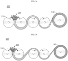
- the mixed powder for an electrode is introduced between a plurality of rolls to carry out calendering, thereby forming an electrode film.
- step 100 of forming an electrode film is illustrated, wherein a plurality of rolls 110 is disposed while being spaced apart from each other.
- the mixed powder 120 for an electrode obtained from the preceding step is introduced between the adjacent rolls 110, and the rolls 110 are rotated in the opposite direction.
- the mixed powder 120 is pressed, and then is subjected to a powder sheeting step so that it may be molded into a sheet or a film.
- calendering is carried out many times to obtain an electrode film having a final target thickness.
- the interval between the rolls may be controlled suitably considering the dimension or physical properties of an electrode film to be obtained in the step of forming an electrode film.
- the interval between the second roll and the third roll and the interval between the fourth roll and the fifth roll may be controlled to a larger value, as compared to FIG. 3a .
- the calendering includes processing the mixed powder for an electrode into the shape of a film.
- the mixed powder for an electrode may be molded into a film having an average thickness of 50-300 ⁇ m.
- the calendering may be carried out by using rolls facing each other.
- the calendering may be carried out repeatedly at least once, for example, once to five times, three or four times, or four times repeatedly.
- the roll temperature may be 50-200°C.
- the roll rotation speed ratio may be controlled suitably depending on the roll size, calendering number, electrode film thickness, or the like.
- the roll rotation speed ratio may be controlled to a range of 1-10 times, 1-8 times, 1-7 times, or 1.2-5 times.
- the gap between a pair of rolls facing each other may be controlled variably depending on the thickness and density of a film to be obtained.
- a dry electrode film functioning as an electrode mixture may be obtained.
- the dry electrode film may also be called a free-sanding film according to the related art.
- the resultant electrode film includes no solvent and has little flowability, and thus can be handled with ease and processed into a desired shape to be used for manufacturing electrodes with various shapes.
- a drying step for removing a solvent can be eliminated, and thus the production processability of the electrode can be improved significantly, and the problems of the methods for manufacturing a dry electrode according to the related art, such as the brittleness of an active material or cutting of a fibrilized binder, can be solved.
- the electrode film may have a porosity of 20-50%.
- the porosity may be controlled to a value of 40% or less, or 30% or less.
- the electrode film satisfies such a range of porosity, it is possible to facilitate wetting with an electrolyte, resulting in improvement of life characteristics, output characteristics, or the like.
- energy density based on volume can be improved, since the volume required to realize the same capacity is not increased.
- the electrode film is laminated on a metallic current collector.
- the lamination step may be a step of pressing and adhering the electrode film obtained from the preceding step onto a current collector to a desired thickness.
- the lamination may also be carried out by using a lamination roll, wherein the lamination roll may be maintained at a temperature of 25-250°C.
- the electrode film may have a compression ratio of 30-50%, 35-50%, or 40-50%.
- the lamination step may be controlled to satisfy a specific compression ratio. In this manner, it is possible to provide the electrode film with adequate density and porosity, and to realize excellent adhesion between the electrode film and the current collector.
- the pressure applied to the electrode film is sufficient so that the adhesion between the electrode film and the current collector may be improved.
- the compression ratio (%) of Formula 1 may be expressed by the following Formula 2: 30 ⁇ T 1 + 0.5 T c ⁇ 0.5 T gap / T 1 ⁇ 100 ⁇ 50 wherein T 1 represents the thickness of an electrode film before the lamination step, T c represents the thickness of a current collector, and T gap represents an interval between a first pressing roll and a second pressing roll.
- the electrode film subjected to the lamination step may have a pressing ratio of 20% or less, 18% or less, 15% or less, 5-15%, 6-15%, 7-15%, or 9-13%.
- the pressing ratio satisfies the above-defined range, it is possible to provide the resultant electrode film with adequate density and porosity, and to realize excellent adhesion between the electrode film and the current collector.
- the electrode film may have an increase in apparent density of 5-30%, 7-25%, or 10-20%, before and after its lamination with the current collector.
- Each of D 1 and D 2 that represents the apparent density of the electrode film may vary with the type of active material.
- M 1 is at least one selected from the group consisting of Zr, B, W, Mg, Ce, Hf, Ta, La, Ti, Sr, Ba, F, P and S, 0.8 ⁇ a ⁇ 1.2, 0.5 ⁇ b
- the electrode film satisfies the above-defined range of an increase in apparent density, it is possible to improve the adhesion between the electrode film and the current collector and to prevent the problem of a porosity beyond the target range or damages to the active material or current collector.
- Such an increase in apparent density before and after the lamination of the electrode film with the current collector may be calculated by measuring the weight and thickness of the electrode film before lamination, measuring the weight and thickness of the electrode after lamination, and calculating the weight and thickness of the film from which the weight and thickness of the current collector are subtracted.
- the dry electrode film may have an active material loading amount of 3-15 mAh/cm 2 , particularly 4-10 mAh/cm 2 .
- the interfacial resistance between the electrode film and the current collector may be 5 ⁇ cm 2 or less, particularly 2 ⁇ cm 2 or less.
- the interfacial resistance may be calculated by determining the resistance value between the dry electrode film and the current collector layer as a potential difference measured among multiple probes, after applying an electric current of 100 ⁇ A to the electrode through the multiprobe (MP) resistance test method.
- MP multiprobe
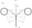
- FIG. 4 is a schematic view illustrating the step of laminating an electrode film on both surfaces of a current collector according to an embodiment of the present disclosure.
- the electrode film 230 obtained from the preceding step may be pressed on and attached to a current collector 220 to a desired thickness by using a pair of lamination rolls 210, thereby providing a finished electrode 240.
- an electrode obtained by the method for manufacturing an electrode as described above.
- a secondary battery including the electrode, wherein the electrode is a positive electrode, and an electrode assembly including the positive electrode, a negative electrode and a separator is received in a battery casing (cylindrical casing, prismatic casing, pouch, or the like) together with a lithium-containing nonaqueous electrolyte.
- a battery casing cylindrical casing, prismatic casing, pouch, or the like
- an energy storage system including the secondary battery as a unit cell.
- a system for manufacturing a dry electrode includes: a blender configured to mix ingredients of an electrode mixture including an active material, a conductive material, a binder and a fluoro-elastomer; a kneader configured to knead the mixture of the ingredients to form mixture lumps; a pulverizer configured to pulverize the mixture lumps to form a mixed powder for an electrode; a calender configured to form a dry electrode film from the mixed powder for an electrode; and a lamination roll configured to dispose the dry electrode film on at least one surface of a current collector and to carry out lamination.
- the blender is a mixer configured to mix the ingredients. As described above, the ingredients of the mixture may be mixed at a rate of 5,000-20,000 rpm.
- the mixer may include a super-mixer, or the like.
- the kneader is a device for fibrilizing a binder and dispersing the ingredients of the mixture according to the present disclosure, and the mixture may be obtained in the form of mixture lumps through the kneading in the kneader.
- the kneader may be set to a temperature of 70-200°C or 90-180°C and a pressure condition equal to or higher than ambient pressure, or a pressure of 1-60 atm, 1-30 atm, 1-10 atm, 1-8 atm, 1.1-7 atm, or 1.1-6 atm.
- the pulverizer is configured to pulverize the obtained mixture lumps to form mixed a powder for an electrode, and may include a blender or a grinder.
- the grinder may include a cutter mill, a fine mill, or the like.
- the calender is a device for molding the mixed powder for an electrode into a film shape.
- the calender may include a pair of rollers facing each other, and the film thickness may be controlled from the interval between the rollers.
- the lamination roll functions to attach the dry electrode film formed by the calender to at least one surface of the current collector and to carry out pressing.
- the porosity of the dry electrode film according to the present disclosure may be determined by the calender and the lamination roll.
- the system for manufacturing a dry electrode according to the present disclosure is characterized by including a kneader and a pulverizer.
- Li 2 MnO 2 lithium manganese oxide
- carbon black as a conductive material
- PTFE polytetrafluoroethylene
- the temperature of the kneader was stabilized at 150°C, the mixture was introduced to the pressurization type kneader, and the kneader was operated under a pressure of about 1.1 atm at a rate of 40 rpm for 5 minutes to obtain mixture lumps.
- the mixture lumps were introduced to a blender, pulverized at 10,000 rpm for 30 seconds, and classified by using a sieve having pores with a size of 1 mm to obtain a mixed powder for an electrode. Then, the resultant mixed powder for an electrode was introduced to a lab calender (roll diameter: 160 mm, roll temperature: 100°C) to obtain an electrode film.
- Electrode films Two sheets of the electrode films were disposed on both surfaces of aluminum foil (thickness 19 ⁇ m, coated with conductive primer layers containing carbon black and an acrylic binder mixed at a weight ratio of 5:6), and lamination was carried out through a compressing roll maintained at 150°C to obtain an electrode (positive electrode).
- the finished electrode had a total thickness of 343 ⁇ m, and the active material layer formed on one surface of the active material layers provided on both surfaces of the current collector had a thickness of 162 ⁇ m.
- a positive electrode was obtained in the same manner as Example 1, except that 10 g of polytetrafluoroethylene (PTFE) was used as a binder, and 10 g of FKM was used as a fluoro-elastomer.
- PTFE polytetrafluoroethylene
- the finished electrode had a total thickness of 342 ⁇ m, and the active material layer formed on one surface of the active material layers provided on both surfaces of the current collector had a thickness of 162 ⁇ m.
- a positive electrode was obtained in the same manner as Example 1, except that 20 g of polytetrafluoroethylene (PTFE) was used as a binder, and 0 g of FKM was used as a fluoro-elastomer.
- PTFE polytetrafluoroethylene
- the finished electrode had a total thickness of 345 ⁇ m, and the active material layer formed on one surface of the active material layers provided on both surfaces of the current collector had a thickness of 163 ⁇ m.
- a positive electrode was obtained in the same manner as Example 1, except that 7 g of polytetrafluoroethylene (PTFE) was used as a binder, and 13 g of FKM was used as a fluoro-elastomer.
- PTFE polytetrafluoroethylene
- the finished electrode had a total thickness of 346 ⁇ m, and the active material layer formed on one surface of the active material layers provided on both surfaces of the current collector had a thickness of 164 ⁇ m.
- a positive electrode was obtained in the same manner as Example 1, except that 0 g of polytetrafluoroethylene (PTFE) was used as a binder, and 20 g of FKM was used as a fluoro-elastomer. However, the resultant electrode film was broken with ease, and thus a positive electrode sample could not be obtained.
- PTFE polytetrafluoroethylene
- Example 1 The positive electrode according to each of Example 1 and Comparative Example 1 and the secondary battery including each positive electrode were evaluated as follows. The results are shown in the following Table 1.
- the secondary battery including the electrode according to each of Example 1 and Comparative Example 1 was obtained as follows.
- Lithium metal was deposited on copper foil to a thickness of 70 ⁇ m to obtain a negative electrode.
- Example 1 The electrode according to each of Example 1 and Comparative Example 1 was used as a positive electrode, and a polyethylene membrane (thickness: 20 ⁇ m) was interposed between the positive electrode and the negative electrode to obtain an electrode assembly.
- the electrode assembly was received in a battery casing, and a liquid electrolyte containing 1 M LiPF 6 dissolved in a solvent including ethylene carbonate, dimethyl carbonate and diethyl carbonate mixed at a ratio of 1:2:1 (volume ratio) was injected to the electrode assembly, followed by sealing, to provide a secondary battery.
- the flexural resistance of each electrode was determined by allowing the electrode to be in contact with test rods having different diameters and lifting both ends of the electrode to judge whether cracks are generated or not and to determine the minimum diameter causing no cracks.
- the flexural resistance of the electrode was evaluated through the steps of:
- the electrode sample when the electrode sample was allowed to be in contact with a test rod by using test rods having a diameter ranging from 32 mm to 3 mm, and both ends of the electrode sample were lifted, no cracks were generated in the mixture film of the electrode sample.
- the electrode sample when the electrode sample was allowed to be in contact with a test rod having a diameter of 2 mm, and both ends of the electrode sample were lifted, cracks were generated in the mixture film of the electrode sample.
- the flexural resistance of the dry electrode was determined as 3 mm ⁇ , i.e. the minimum diameter value of test rod causing no cracks in the mixture film of the electrode sample.
- the electrodes according to Examples 1 and 2 show improvement in property of breaking when impact or deformation is generated, and thus realize excellent flexural resistance, compared to the electrodes according to Comparative Examples 1-3.
Landscapes
- Chemical & Material Sciences (AREA)
- Chemical Kinetics & Catalysis (AREA)
- Electrochemistry (AREA)
- General Chemical & Material Sciences (AREA)
- Engineering & Computer Science (AREA)
- Manufacturing & Machinery (AREA)
- Materials Engineering (AREA)
- Health & Medical Sciences (AREA)
- Physics & Mathematics (AREA)
- Life Sciences & Earth Sciences (AREA)
- Analytical Chemistry (AREA)
- Biochemistry (AREA)
- General Health & Medical Sciences (AREA)
- General Physics & Mathematics (AREA)
- Immunology (AREA)
- Pathology (AREA)
- Composite Materials (AREA)
- Battery Electrode And Active Subsutance (AREA)
- Cell Electrode Carriers And Collectors (AREA)
Applications Claiming Priority (2)
| Application Number | Priority Date | Filing Date | Title |
|---|---|---|---|
| KR1020220049213A KR102948297B1 (ko) | 2022-04-20 | 2022-04-20 | 전극, 이를 포함하는 이차전지, 및 이의 제조 방법 |
| PCT/KR2023/005414 WO2023204647A1 (fr) | 2022-04-20 | 2023-04-20 | Électrode, batterie secondaire la comprenant, et son procédé de fabrication |
Publications (2)
| Publication Number | Publication Date |
|---|---|
| EP4513583A1 true EP4513583A1 (fr) | 2025-02-26 |
| EP4513583A4 EP4513583A4 (fr) | 2026-01-14 |
Family
ID=88420212
Family Applications (1)
| Application Number | Title | Priority Date | Filing Date |
|---|---|---|---|
| EP23792221.6A Pending EP4513583A4 (fr) | 2022-04-20 | 2023-04-20 | Électrode, batterie secondaire la comprenant, et son procédé de fabrication |
Country Status (6)
| Country | Link |
|---|---|
| US (1) | US20250343239A1 (fr) |
| EP (1) | EP4513583A4 (fr) |
| JP (1) | JP2025513523A (fr) |
| KR (1) | KR102948297B1 (fr) |
| CN (1) | CN119404319A (fr) |
| WO (1) | WO2023204647A1 (fr) |
Family Cites Families (11)
| Publication number | Priority date | Publication date | Assignee | Title |
|---|---|---|---|---|
| JPH09259890A (ja) * | 1996-03-21 | 1997-10-03 | Dainippon Printing Co Ltd | 電極塗布液及び非水電解液二次電池用電極板 |
| JP2001230158A (ja) * | 2000-02-15 | 2001-08-24 | Ngk Insulators Ltd | キャパシタ用分極性電極の製造方法 |
| US20050266298A1 (en) * | 2003-07-09 | 2005-12-01 | Maxwell Technologies, Inc. | Dry particle based electro-chemical device and methods of making same |
| JP5382120B2 (ja) * | 2009-07-03 | 2014-01-08 | ダイキン工業株式会社 | リチウム二次電池の電極合剤用スラリー、該スラリーを用いた電極およびリチウム二次電池 |
| JP5758256B2 (ja) * | 2011-09-28 | 2015-08-05 | 住友化学株式会社 | 微細リチウム二次電池用正極材粉末の製造方法 |
| CN106463267A (zh) * | 2014-04-18 | 2017-02-22 | 麦斯韦尔技术股份有限公司 | 干式储能装置电极及其制造方法 |
| JP6436306B2 (ja) * | 2014-08-25 | 2018-12-12 | パナソニックIpマネジメント株式会社 | 塗膜物の製造装置、及びこれを用いた塗膜物の製造方法 |
| US11532823B2 (en) * | 2016-06-14 | 2022-12-20 | Solvay Sa | Flexible battery |
| US11276846B2 (en) * | 2017-09-25 | 2022-03-15 | Lg Energy Solution, Ltd. | Method for manufacturing electrode for secondary battery and electrode manufactured thereby |
| EP3996167A4 (fr) * | 2019-07-01 | 2023-08-16 | Daikin Industries, Ltd. | Composition pour dispositif électrochimique, mélange d'électrode positive, structure d'électrode positive et batterie secondaire |
| KR102517792B1 (ko) | 2020-10-14 | 2023-04-03 | 조선대학교산학협력단 | 스마트 가로등 제어 시스템 및 이의 동작 방법 |
-
2022
- 2022-04-20 KR KR1020220049213A patent/KR102948297B1/ko active Active
-
2023
- 2023-04-20 US US18/858,389 patent/US20250343239A1/en active Pending
- 2023-04-20 JP JP2024562285A patent/JP2025513523A/ja active Pending
- 2023-04-20 WO PCT/KR2023/005414 patent/WO2023204647A1/fr not_active Ceased
- 2023-04-20 EP EP23792221.6A patent/EP4513583A4/fr active Pending
- 2023-04-20 CN CN202380035118.5A patent/CN119404319A/zh active Pending
Also Published As
| Publication number | Publication date |
|---|---|
| CN119404319A (zh) | 2025-02-07 |
| US20250343239A1 (en) | 2025-11-06 |
| KR20230149677A (ko) | 2023-10-27 |
| KR102948297B1 (ko) | 2026-04-02 |
| JP2025513523A (ja) | 2025-04-24 |
| WO2023204647A1 (fr) | 2023-10-26 |
| EP4513583A4 (fr) | 2026-01-14 |
Similar Documents
| Publication | Publication Date | Title |
|---|---|---|
| US12586773B2 (en) | Powder for electrode for manufacturing dry electrode for secondary battery, method for preparing the same, method for manufacturing dry electrode using the same, dry electrode, secondary battery including the same, energy storage apparatus | |
| EP4152445B1 (fr) | Électrode pour dispositif électrochimique comprenant un film d'électrode sec et son procédé de fabrication | |
| EP4318650A1 (fr) | Système et procédé de fabrication de film d'électrode sèche | |
| US20250279423A1 (en) | Electrode Film, Electrode Including the Same, Secondary Battery, and Method for Manufacturing the Same | |
| CA3227840A1 (fr) | Electrode pour dispositif electrochimique comprenant un film d'electrode seche et son procede de fabrication | |
| EP4465407A1 (fr) | Ensemble d'électrodes et batterie secondaire comprenant celui-ci | |
| KR102851921B1 (ko) | 이차전지의 건식 전극용 필름 | |
| JP2025164796A (ja) | 電極、これを含む二次電池、及びこの製造方法 | |
| EP4513583A1 (fr) | Électrode, batterie secondaire la comprenant, et son procédé de fabrication | |
| KR20230149672A (ko) | 도전재-불소계 고무 복합체, 상기 복합체를 포함하는 전극용 혼합 분체, 상기 전극용 혼합 분체를 제조하는 방법 및 상기 전극용 혼합 분체를 포함하는 전기화학소자용 전극 | |
| KR20230128215A (ko) | 전극용 필름, 이를 포함하는 전극, 이를 포함하는 이차전지, 및 이의 제조 방법 | |
| CN117916905A (zh) | 电极、包括该电极的二次电池以及制造该电极的方法 |
Legal Events
| Date | Code | Title | Description |
|---|---|---|---|
| STAA | Information on the status of an ep patent application or granted ep patent |
Free format text: STATUS: THE INTERNATIONAL PUBLICATION HAS BEEN MADE |
|
| PUAI | Public reference made under article 153(3) epc to a published international application that has entered the european phase |
Free format text: ORIGINAL CODE: 0009012 |
|
| STAA | Information on the status of an ep patent application or granted ep patent |
Free format text: STATUS: REQUEST FOR EXAMINATION WAS MADE |
|
| 17P | Request for examination filed |
Effective date: 20241119 |
|
| AK | Designated contracting states |
Kind code of ref document: A1 Designated state(s): AL AT BE BG CH CY CZ DE DK EE ES FI FR GB GR HR HU IE IS IT LI LT LU LV MC ME MK MT NL NO PL PT RO RS SE SI SK SM TR |
|
| DAV | Request for validation of the european patent (deleted) | ||
| DAX | Request for extension of the european patent (deleted) | ||
| A4 | Supplementary search report drawn up and despatched |
Effective date: 20251212 |
|
| RIC1 | Information provided on ipc code assigned before grant |
Ipc: H01M 4/13 20100101AFI20251208BHEP Ipc: H01M 4/04 20060101ALI20251208BHEP Ipc: H01M 4/139 20100101ALI20251208BHEP Ipc: H01M 4/62 20060101ALI20251208BHEP Ipc: H01M 4/66 20060101ALI20251208BHEP Ipc: H01M 10/052 20100101ALI20251208BHEP Ipc: H01M 4/02 20060101ALI20251208BHEP |