EP4513637A1 - Batterie secondaire - Google Patents
Batterie secondaire Download PDFInfo
- Publication number
- EP4513637A1 EP4513637A1 EP24172974.8A EP24172974A EP4513637A1 EP 4513637 A1 EP4513637 A1 EP 4513637A1 EP 24172974 A EP24172974 A EP 24172974A EP 4513637 A1 EP4513637 A1 EP 4513637A1
- Authority
- EP
- European Patent Office
- Prior art keywords
- plate
- secondary battery
- current collector
- terminal
- electrode assembly
- Prior art date
- Legal status (The legal status is an assumption and is not a legal conclusion. Google has not performed a legal analysis and makes no representation as to the accuracy of the status listed.)
- Pending
Links
Images


Classifications
-
- H—ELECTRICITY
- H01—ELECTRIC ELEMENTS
- H01M—PROCESSES OR MEANS, e.g. BATTERIES, FOR THE DIRECT CONVERSION OF CHEMICAL ENERGY INTO ELECTRICAL ENERGY
- H01M50/00—Constructional details or processes of manufacture of the non-active parts of electrochemical cells other than fuel cells, e.g. hybrid cells
- H01M50/50—Current conducting connections for cells or batteries
- H01M50/531—Electrode connections inside a battery casing
-
- H—ELECTRICITY
- H01—ELECTRIC ELEMENTS
- H01M—PROCESSES OR MEANS, e.g. BATTERIES, FOR THE DIRECT CONVERSION OF CHEMICAL ENERGY INTO ELECTRICAL ENERGY
- H01M10/00—Secondary cells; Manufacture thereof
- H01M10/05—Accumulators with non-aqueous electrolyte
- H01M10/052—Li-accumulators
-
- H—ELECTRICITY
- H01—ELECTRIC ELEMENTS
- H01M—PROCESSES OR MEANS, e.g. BATTERIES, FOR THE DIRECT CONVERSION OF CHEMICAL ENERGY INTO ELECTRICAL ENERGY
- H01M10/00—Secondary cells; Manufacture thereof
- H01M10/05—Accumulators with non-aqueous electrolyte
- H01M10/052—Li-accumulators
- H01M10/0525—Rocking-chair batteries, i.e. batteries with lithium insertion or intercalation in both electrodes; Lithium-ion batteries
-
- H—ELECTRICITY
- H01—ELECTRIC ELEMENTS
- H01M—PROCESSES OR MEANS, e.g. BATTERIES, FOR THE DIRECT CONVERSION OF CHEMICAL ENERGY INTO ELECTRICAL ENERGY
- H01M10/00—Secondary cells; Manufacture thereof
- H01M10/05—Accumulators with non-aqueous electrolyte
- H01M10/058—Construction or manufacture
- H01M10/0585—Construction or manufacture of accumulators having only flat construction elements, i.e. flat positive electrodes, flat negative electrodes and flat separators
-
- H—ELECTRICITY
- H01—ELECTRIC ELEMENTS
- H01M—PROCESSES OR MEANS, e.g. BATTERIES, FOR THE DIRECT CONVERSION OF CHEMICAL ENERGY INTO ELECTRICAL ENERGY
- H01M10/00—Secondary cells; Manufacture thereof
- H01M10/05—Accumulators with non-aqueous electrolyte
- H01M10/058—Construction or manufacture
- H01M10/0587—Construction or manufacture of accumulators having only wound construction elements, i.e. wound positive electrodes, wound negative electrodes and wound separators
-
- H—ELECTRICITY
- H01—ELECTRIC ELEMENTS
- H01M—PROCESSES OR MEANS, e.g. BATTERIES, FOR THE DIRECT CONVERSION OF CHEMICAL ENERGY INTO ELECTRICAL ENERGY
- H01M50/00—Constructional details or processes of manufacture of the non-active parts of electrochemical cells other than fuel cells, e.g. hybrid cells
- H01M50/10—Primary casings; Jackets or wrappings
- H01M50/102—Primary casings; Jackets or wrappings characterised by their shape or physical structure
- H01M50/103—Primary casings; Jackets or wrappings characterised by their shape or physical structure prismatic or rectangular
-
- H—ELECTRICITY
- H01—ELECTRIC ELEMENTS
- H01M—PROCESSES OR MEANS, e.g. BATTERIES, FOR THE DIRECT CONVERSION OF CHEMICAL ENERGY INTO ELECTRICAL ENERGY
- H01M50/00—Constructional details or processes of manufacture of the non-active parts of electrochemical cells other than fuel cells, e.g. hybrid cells
- H01M50/10—Primary casings; Jackets or wrappings
- H01M50/147—Lids or covers
- H01M50/148—Lids or covers characterised by their shape
- H01M50/15—Lids or covers characterised by their shape for prismatic or rectangular cells
-
- H—ELECTRICITY
- H01—ELECTRIC ELEMENTS
- H01M—PROCESSES OR MEANS, e.g. BATTERIES, FOR THE DIRECT CONVERSION OF CHEMICAL ENERGY INTO ELECTRICAL ENERGY
- H01M50/00—Constructional details or processes of manufacture of the non-active parts of electrochemical cells other than fuel cells, e.g. hybrid cells
- H01M50/10—Primary casings; Jackets or wrappings
- H01M50/147—Lids or covers
- H01M50/166—Lids or covers characterised by the methods of assembling casings with lids
- H01M50/169—Lids or covers characterised by the methods of assembling casings with lids by welding, brazing or soldering
-
- H—ELECTRICITY
- H01—ELECTRIC ELEMENTS
- H01M—PROCESSES OR MEANS, e.g. BATTERIES, FOR THE DIRECT CONVERSION OF CHEMICAL ENERGY INTO ELECTRICAL ENERGY
- H01M50/00—Constructional details or processes of manufacture of the non-active parts of electrochemical cells other than fuel cells, e.g. hybrid cells
- H01M50/10—Primary casings; Jackets or wrappings
- H01M50/172—Arrangements of electric connectors penetrating the casing
- H01M50/174—Arrangements of electric connectors penetrating the casing adapted for the shape of the cells
- H01M50/176—Arrangements of electric connectors penetrating the casing adapted for the shape of the cells for prismatic or rectangular cells
-
- H—ELECTRICITY
- H01—ELECTRIC ELEMENTS
- H01M—PROCESSES OR MEANS, e.g. BATTERIES, FOR THE DIRECT CONVERSION OF CHEMICAL ENERGY INTO ELECTRICAL ENERGY
- H01M50/00—Constructional details or processes of manufacture of the non-active parts of electrochemical cells other than fuel cells, e.g. hybrid cells
- H01M50/10—Primary casings; Jackets or wrappings
- H01M50/183—Sealing members
- H01M50/186—Sealing members characterised by the disposition of the sealing members
- H01M50/188—Sealing members characterised by the disposition of the sealing members the sealing members being arranged between the lid and terminal
-
- H—ELECTRICITY
- H01—ELECTRIC ELEMENTS
- H01M—PROCESSES OR MEANS, e.g. BATTERIES, FOR THE DIRECT CONVERSION OF CHEMICAL ENERGY INTO ELECTRICAL ENERGY
- H01M50/00—Constructional details or processes of manufacture of the non-active parts of electrochemical cells other than fuel cells, e.g. hybrid cells
- H01M50/30—Arrangements for facilitating escape of gases
-
- H—ELECTRICITY
- H01—ELECTRIC ELEMENTS
- H01M—PROCESSES OR MEANS, e.g. BATTERIES, FOR THE DIRECT CONVERSION OF CHEMICAL ENERGY INTO ELECTRICAL ENERGY
- H01M50/00—Constructional details or processes of manufacture of the non-active parts of electrochemical cells other than fuel cells, e.g. hybrid cells
- H01M50/30—Arrangements for facilitating escape of gases
- H01M50/342—Non-re-sealable arrangements
- H01M50/3425—Non-re-sealable arrangements in the form of rupturable membranes or weakened parts, e.g. pierced with the aid of a sharp member
-
- H—ELECTRICITY
- H01—ELECTRIC ELEMENTS
- H01M—PROCESSES OR MEANS, e.g. BATTERIES, FOR THE DIRECT CONVERSION OF CHEMICAL ENERGY INTO ELECTRICAL ENERGY
- H01M50/00—Constructional details or processes of manufacture of the non-active parts of electrochemical cells other than fuel cells, e.g. hybrid cells
- H01M50/50—Current conducting connections for cells or batteries
- H01M50/528—Fixed electrical connections, i.e. not intended for disconnection
-
- H—ELECTRICITY
- H01—ELECTRIC ELEMENTS
- H01M—PROCESSES OR MEANS, e.g. BATTERIES, FOR THE DIRECT CONVERSION OF CHEMICAL ENERGY INTO ELECTRICAL ENERGY
- H01M50/00—Constructional details or processes of manufacture of the non-active parts of electrochemical cells other than fuel cells, e.g. hybrid cells
- H01M50/50—Current conducting connections for cells or batteries
- H01M50/531—Electrode connections inside a battery casing
- H01M50/533—Electrode connections inside a battery casing characterised by the shape of the leads or tabs
-
- H—ELECTRICITY
- H01—ELECTRIC ELEMENTS
- H01M—PROCESSES OR MEANS, e.g. BATTERIES, FOR THE DIRECT CONVERSION OF CHEMICAL ENERGY INTO ELECTRICAL ENERGY
- H01M50/00—Constructional details or processes of manufacture of the non-active parts of electrochemical cells other than fuel cells, e.g. hybrid cells
- H01M50/50—Current conducting connections for cells or batteries
- H01M50/543—Terminals
- H01M50/545—Terminals formed by the casing of the cells
-
- H—ELECTRICITY
- H01—ELECTRIC ELEMENTS
- H01M—PROCESSES OR MEANS, e.g. BATTERIES, FOR THE DIRECT CONVERSION OF CHEMICAL ENERGY INTO ELECTRICAL ENERGY
- H01M50/00—Constructional details or processes of manufacture of the non-active parts of electrochemical cells other than fuel cells, e.g. hybrid cells
- H01M50/50—Current conducting connections for cells or batteries
- H01M50/543—Terminals
- H01M50/547—Terminals characterised by the disposition of the terminals on the cells
- H01M50/548—Terminals characterised by the disposition of the terminals on the cells on opposite sides of the cell
-
- H—ELECTRICITY
- H01—ELECTRIC ELEMENTS
- H01M—PROCESSES OR MEANS, e.g. BATTERIES, FOR THE DIRECT CONVERSION OF CHEMICAL ENERGY INTO ELECTRICAL ENERGY
- H01M50/00—Constructional details or processes of manufacture of the non-active parts of electrochemical cells other than fuel cells, e.g. hybrid cells
- H01M50/50—Current conducting connections for cells or batteries
- H01M50/543—Terminals
- H01M50/547—Terminals characterised by the disposition of the terminals on the cells
- H01M50/55—Terminals characterised by the disposition of the terminals on the cells on the same side of the cell
-
- H—ELECTRICITY
- H01—ELECTRIC ELEMENTS
- H01M—PROCESSES OR MEANS, e.g. BATTERIES, FOR THE DIRECT CONVERSION OF CHEMICAL ENERGY INTO ELECTRICAL ENERGY
- H01M50/00—Constructional details or processes of manufacture of the non-active parts of electrochemical cells other than fuel cells, e.g. hybrid cells
- H01M50/50—Current conducting connections for cells or batteries
- H01M50/572—Means for preventing undesired use or discharge
- H01M50/584—Means for preventing undesired use or discharge for preventing incorrect connections inside or outside the batteries
- H01M50/586—Means for preventing undesired use or discharge for preventing incorrect connections inside or outside the batteries inside the batteries, e.g. incorrect connections of electrodes
-
- H—ELECTRICITY
- H01—ELECTRIC ELEMENTS
- H01M—PROCESSES OR MEANS, e.g. BATTERIES, FOR THE DIRECT CONVERSION OF CHEMICAL ENERGY INTO ELECTRICAL ENERGY
- H01M50/00—Constructional details or processes of manufacture of the non-active parts of electrochemical cells other than fuel cells, e.g. hybrid cells
- H01M50/50—Current conducting connections for cells or batteries
- H01M50/572—Means for preventing undesired use or discharge
- H01M50/584—Means for preventing undesired use or discharge for preventing incorrect connections inside or outside the batteries
- H01M50/59—Means for preventing undesired use or discharge for preventing incorrect connections inside or outside the batteries characterised by the protection means
- H01M50/593—Spacers; Insulating plates
-
- H—ELECTRICITY
- H01—ELECTRIC ELEMENTS
- H01M—PROCESSES OR MEANS, e.g. BATTERIES, FOR THE DIRECT CONVERSION OF CHEMICAL ENERGY INTO ELECTRICAL ENERGY
- H01M50/00—Constructional details or processes of manufacture of the non-active parts of electrochemical cells other than fuel cells, e.g. hybrid cells
- H01M50/60—Arrangements or processes for filling or topping-up with liquids; Arrangements or processes for draining liquids from casings
- H01M50/609—Arrangements or processes for filling with liquid, e.g. electrolytes
- H01M50/627—Filling ports
-
- H—ELECTRICITY
- H01—ELECTRIC ELEMENTS
- H01M—PROCESSES OR MEANS, e.g. BATTERIES, FOR THE DIRECT CONVERSION OF CHEMICAL ENERGY INTO ELECTRICAL ENERGY
- H01M50/00—Constructional details or processes of manufacture of the non-active parts of electrochemical cells other than fuel cells, e.g. hybrid cells
- H01M50/60—Arrangements or processes for filling or topping-up with liquids; Arrangements or processes for draining liquids from casings
- H01M50/609—Arrangements or processes for filling with liquid, e.g. electrolytes
- H01M50/627—Filling ports
- H01M50/636—Closing or sealing filling ports, e.g. using lids
- H01M50/645—Plugs
-
- Y—GENERAL TAGGING OF NEW TECHNOLOGICAL DEVELOPMENTS; GENERAL TAGGING OF CROSS-SECTIONAL TECHNOLOGIES SPANNING OVER SEVERAL SECTIONS OF THE IPC; TECHNICAL SUBJECTS COVERED BY FORMER USPC CROSS-REFERENCE ART COLLECTIONS [XRACs] AND DIGESTS
- Y02—TECHNOLOGIES OR APPLICATIONS FOR MITIGATION OR ADAPTATION AGAINST CLIMATE CHANGE
- Y02E—REDUCTION OF GREENHOUSE GAS [GHG] EMISSIONS, RELATED TO ENERGY GENERATION, TRANSMISSION OR DISTRIBUTION
- Y02E60/00—Enabling technologies; Technologies with a potential or indirect contribution to GHG emissions mitigation
- Y02E60/10—Energy storage using batteries
Definitions
- aspects of embodiments of the present disclosure relate to a secondary battery.
- Secondary batteries are rechargeable, unlike primary batteries.
- a low-capacity battery including a battery cell in the form of a pack may be used in portable small electronic devices, such as smartphones and digital cameras, and a high-capacity battery module including tens to hundreds of battery packs connected to each other may be used as a power source for driving motors, e.g., of hybrid vehicles, electric vehicles, and the like.
- a rechargeable secondary battery includes an electrode assembly, in which a separator is interposed between a positive electrode plate and a negative electrode plate, a current collector plate electrically connected to the electrode assembly, a terminal electrically connected to the current collector plate, a case accommodating the electrode assembly and the current collector plate, and a cap plate which seals the case and through which the terminal passes to be coupled.
- a secondary battery that has an improved anti-vibration property and is improved in terms of energy density or a current flow is provided.
- a secondary battery includes: an electrode assembly including a first tab and a second tab at opposite ends of the electrode assembly in a longitudinal direction, respectively; a case configured to accommodate the electrode assembly and in which a first opening and a second opening are defined at opposite ends of the case in the longitudinal direction, respectively; a first cap plate coupled to the first opening of the case and insulated from and penetrated by a first terminal that is electrically coupled to the first tab of the electrode assembly, the first cap plate including a second terminal electrically coupled to the second tab of the electrode assembly; and a second cap plate coupled to the second opening of the case and electrically coupled to the second tab of the electrode assembly.
- the secondary battery may further include a first current collector plate configured to electrically couple the first tab to the first terminal.
- the first current collector plate may include: a first current collector plate flat part welded to the first tab; and a first current collector plate protrusion welded to the first terminal.
- the secondary battery may further include a first insulating plate between the first current collector plate and the first cap plate, and may even further include a first insulating plate through-hole through which the first current collector plate protrusion passes.
- the secondary battery may further include a second current collector plate configured to electrically couple the second tab to the second cap plate.
- the second current collector plate may include: a second current collector plate flat part welded to the second tab; and a second current collector plate protrusion welded to the second cap plate.
- the secondary battery may further include a second insulating plate between the second current collector plate and the second cap plate, and may even further include a second insulating plate through-hole through which the second current collector plate protrusion passes.
- the second cap plate may include a second cap plate protrusion welded to the second current collector plate protrusion.
- the second cap plate may include a vent hole and a safety vent coupled to the vent hole.
- the second insulating plate may include a vent through-hole in a region corresponding to the safety vent.
- the first cap plate may include a main through-hole through which the first terminal passes and a sub through-hole around the main through-hole, and the first cap plate may further include an insulating member coupled to the main through-hole and the sub through-hole to insulate the first terminal from the first cap plate.
- the case may include a pair of long sides and a pair of short sides connected to the pair of long sides, and a welding line may be provided on at least one short side of the pair of short sides.
- the electrode assembly may include a pair of long sides and a pair of short sides connected to the pair of long sides, and the secondary battery may further include a short-side insulating plate between a short side of the pair of short sides and the case.
- the first cap plate may further include a second terminal accommodation recess and a second terminal accommodation protrusion, and the second terminal may be accommodated in the second terminal accommodation recess and coupled to the second terminal accommodation protrusion.
- the second cap plate may further include a liquid injection hole and a plug configured to block the liquid injection hole.
- Each of the electrode assembly and the case may have a vertical length greater than a horizontal width.
- each layer may be exaggerated for convenience and clarity of description, and the same reference numerals in the drawings refer to the same elements.
- the term "and/or" includes any and all combinations of one or more of the associated listed items. In this specification, it is to be understood that if a member A is referred to as being connected to a member B, the member A may be directly connected to the member B or indirectly connected to the member B with one or more members C therebetween.
- first As used herein, terms such as "first,” “second,” etc. are used to describe various members, components, areas, layers, and/or portions. However, it is to be understood that the members, components, areas, layers, and/or portions should not be defined by these terms. The terms do not mean a particular order, up and down, or superiority, and are used for distinguishing one member, component, region, layer, or portion from another member, component, region, layer, or portion. Thus, a first member, component, region, layer, or portion which will be described may also refer to a second member, component, region, layer, or portion, without departing from the teaching of the present disclosure.
- FIG. 1 illustrates a perspective view of a secondary battery 100 according to an embodiment
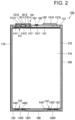
- FIG. 2 is a cross-sectional view illustrating the secondary battery 100, taken along the line 2-2 of FIG. 1 , according to an embodiment
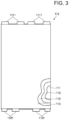
- FIG. 3 illustrates a plan view of an electrode assembly 110 in the secondary battery 100 according to an embodiment
- FIG. 4 illustrates an exploded perspective view of the secondary battery 100 according to an embodiment.
- the electrode assembly 110 in FIG. 3 illustrates a state before a first tab 1111 and a second tab 1121 are bent.
- the secondary battery 100 may include the electrode assembly 110, a case 120, a first cap plate 131, and a second cap plate 132.
- the secondary battery 100 may further include a first current collector plate 141 and a second current collector plate 142.
- the secondary battery 100 may further include a first insulating plate 151 and a second insulating plate 152.
- the secondary battery 100 may further include a first terminal 161 and a second terminal 162.
- the secondary battery 100 according to the present disclosure may further include a short-side insulating plate 170.
- the secondary battery 100 may further include a safety vent 180, a liquid injection metal ball 191, and a liquid injection plug 192.
- the electrode assembly 110 may be provided in the form of a substantially rectangular hexahedral shape having a pair of long sides in a longitudinal direction and a pair of short sides in the longitudinal direction.
- a surface area of each of the long sides may be wider than that of each of the short sides.
- the long side and/or the short side may have a length and a width.
- the length may be longer than the width. In some embodiments, the length may be approximately 200 mm to approximately 400 mm.
- the electrode assembly 110 may include a first electrode plate 111 (e.g., a positive electrode plate), a second electrode plate 112 (e.g., a negative electrode plate), and a separator 113 between the first electrode plate 111 and the second electrode plate 112.
- the first electrode plate 111 may include a plurality of first tabs 1111 (e.g., positive electrode tabs) protruding to the outside (e.g., at an upper side) of the electrode assembly 110
- the second electrode plate 112 may include a plurality of second tabs 1121 (e.g., negative electrode tabs) protruding to the outside (e.g., at a lower side) of the electrode assembly 110.
- the electrode assembly 110 may include a first tab 1111 provided on an end (for example, an upper end) in the longitudinal direction and a second tab 1121 provided on an opposite end (for example, a lower end) in the longitudinal direction.
- the electrode assembly 110 may be of a stack type in which the first electrode plate 111, the separator 113, and the second electrode plate 112 are stacked, or a winding type in which the first electrode plate 111, the separator 113, and the second electrode plate 112 are wound.
- the electrode assembly 110 may include or be referred to as an electrode group.
- the second electrode plate 112 may be provided by applying a second active material, such as graphite or carbon, to a second current collector made of metal foil, such as copper or nickel, and may include the second tab 1121 (e.g., an area that is not coated with the second active material) extending and protruding toward the second cap plate 132 of a current collector.
- the second tab 1121 extending and protruding in this manner may also be referred to as a second non-coating portion tab or a second base material tab, and the second tabs 1121 may be aligned at a same position through a stacking or winding process for manufacturing the electrode assembly 110 to provide a multi-tab.
- the second tab 1121 may be electrically connected to the second terminal 162 to serve as a passage through which current flows between the second electrode plate 112 and the second terminal 162.
- the separator 113 may be interposed between the first electrode plate 111 and the second electrode plate 112 to prevent or substantially prevent a short circuit between the first electrode plate 111 and the second electrode plate 112 and enable movement of lithium ions.
- the separator 113 may be wider (e.g., slightly wider) than a surface area of each of the first electrode plate 111 and the second electrode plate 112 to further protrude in an upward and downward direction and/or a left and right direction than each of the first electrode plate 111 and the second electrode plate 112.
- the separator 113 may prevent or substantially prevent the first electrode plate 111 and the second electrode plate 112 from being in direct contact with the case 120, the first cap plate 131, and the second cap plate 132 in the upward and downward direction and/or left and right direction of the electrode assembly 110.
- the electrode assembly 110 may be accommodated in the case 120 together with an electrolyte.
- the electrolyte may include an organic solvent, such as ethylene carbonate (EC), propylene carbonate (PC), diethyl carbonate (DEC), ethylmethyl carbonate (EMC), and/or dimethyl carbonate (DMC), and lithium salt, such as LiPF 6 or LiBF 4 .
- the electrolyte may be liquid, solid, or gel.
- the case 120 may accommodate the electrode assembly 110 and may include a first opening 121 and a second opening 122, which are provided at opposite ends in the longitudinal direction.
- the case 120 may be provided in the form of a substantially rectangular hexahedral shape having a pair of long sides in the longitudinal direction and a pair of short sides in the longitudinal direction.
- a surface area of each of the long sides may be wider than that of each of the short sides.
- the long side and/or the short side may have a length and a width.
- the length may be longer than the width. In some embodiments, the length may be approximately 200 mm to approximately 400 mm.
- the first opening 121 may be an upper opening defined by the pair of long sides and the pair of short sides
- the second opening 122 may be a lower opening defined by the pair of long sides and the pair of short sides
- the case 120 may include at least one welding line 123 provided in the longitudinal direction of the short sides.
- the case 120 may be provided by bending a metal flat plate into a hollow rectangular hexahedral shape and then laser welding ends to each other.
- the welding line 123 may be provided.
- the case 120 may be provided by extruding molten metal into an empty tube shape.
- the case 120 may be manufactured in a deep drawing manner and then be cut at a side thereof to provide the case 120 with both sides open.
- the case 120 may be made of a conductive metal, such as aluminum, an aluminum alloy, or steel plated with nickel.
- case 120 may include or be referred to as a can.
- the long side of the case 120 may be in close contact with the long side of the electrode assembly 110, and the short side of the case 120 may be in close contact with the short side of the electrode assembly 110.
- the first cap plate 131 may be provided in a substantially rectangular plate shape and may be coupled to the first opening 121 of the case 120. In some embodiments, the cap plate 131 may close (or seal) the first opening 121 of the case 120 and may be laser welded to the case 120. In some embodiments, the first cap plate 131 may include a liquid injection hole 1311 through which an electrolyte may be injected. The liquid injection hole 1311 may be closed with a metal ball 191 and a plug 192. In some embodiments, the first terminal 161 electrically coupled to the first tab 1111 of the electrode assembly 110 may be insulated from and penetrate the first cap plate 131.
- the second terminal 162 electrically coupled to the second tab 1121 of the electrode assembly 110 may be coupled to the first cap plate 131.
- the second terminal 162 may be provided to be integrated with the first cap plate 131 or may be mechanically coupled (electrically short-circuited) to the first cap plate 131.
- the first cap plate 131 may be made of a conductive metal, such as aluminum, an aluminum alloy, or nickel-plated steel and may also be referred to as a cap assembly in some cases.
- the second cap plate 132 may be provided in a substantially rectangular plate shape and may be coupled to the second opening 122 of the case 120. In some embodiments, the second cap plate 132 may close (or seal) the second opening 122 of the case 120 and may be laser welded to the case 120. In some embodiments, the second cap plate 132 may further include a vent hole 1321 into which the safety vent 180 is coupled. In some embodiments, the second cap plate 132 may further include a second cap plate protrusion 1322 that is electrically coupled to the second tab 1121 of the electrode assembly 110. In some embodiments, the second cap plate protrusion 1322 may be provided at each of opposite sides of the vent hole 1321.
- the second cap plate protrusion 1322 may have a shape that protrudes toward the second tab 1121.
- the second cap plate protrusion 1322 may be provided by placing the second cap plate 132, which is provided in the form of a flat plate, on a mold or die and then pressing a partial area of the second cap plate 132 through a punch.
- thicknesses of the second cap plate 132 and the second cap plate protrusion 1322 may be the same or similar.
- the second cap plate 132 may be made of a conductive metal, such as aluminum, an aluminum alloy, or nickel-plated steel and may also be referred to as a cap assembly in some cases.
- the first current collector plate 141 may be interposed between the electrode assembly 110 and the first cap plate 131.
- the first current collector plate 141 may have a substantially rectangular plate shape.
- the first current collector plate 141 may electrically/mechanically couple the first tab 1111 of the electrode assembly 110 to the first terminal 161.
- the first current collector plate 141 may include a first current collector plate flat part 1411 welded (e.g., laser welded) to the first tab 1111 and a first current collector plate protrusion 1412 welded (e.g., laser welded) to the first terminal 161.
- the first tab 1111 of the electrode assembly 110 may be bent in a direction to facilitate the welding to the first current collector flat part 1411.
- the first tabs 1111 may be bent and in close contact with a surface of the electrode assembly 110 and thus may be pre-welded to each other.
- a terminal pillar 1611 which is a component of the first terminal 161, may be welded on the first current collector plate protrusion 1412 in advance.
- the terminal pillar 1611 may include a base 1611a welded on the first current collector plate protrusion 1412 and a cylindrical-type protrusion 1611b protruding in a direction away from the base 1611a.
- the first current collector plate 141 may be made of a conductive metal, such as aluminum, an aluminum alloy, or nickel-plated steel, and may also be referred to as a current collector or sub plate in some cases.
- the second current collector plate 142 may be interposed between the electrode assembly 110 and the second cap plate 132.
- the second current collector plate 142 may have a substantially rectangular plate shape.
- the second current collector plate 142 may electrically couple the second tab 1121 of the electrode assembly 110 to the second terminal 162.
- the second current collector plate 142 may electrically/mechanically couple the second tab 1121 to the second cap plate 132.
- the second current collector plate 142 may include a second current collector plate flat part 1421 welded (e.g., laser welded) to the second tab 1121 and a second current collector plate protrusion 1422 welded (e.g., laser welded) to the second cap plate 132.
- the second current collector plate protrusion 1422 may be welded to the second cap plate protrusion 1322.
- two second cap plate protrusions 1322 are provided, and, thus, two second current collector plates 142 may be provided.
- the second tab 1121 of the electrode assembly 110 may be bent in a direction to facilitate the welding to the second current collector flat part 1421.
- the second tabs 1121 may be bent and in close contact with a surface of the electrode assembly 110 and thus may be pre-welded to each other.
- the second current collector plate 142 may be made of a conductive metal, such as copper, a copper alloy, nickel, a nickel alloy, or nickel-plated steel, and may also be referred to as a current collector or sub plate in some cases.
- the first insulating plate 151 may be interposed between the first current collector plate 141 and the first cap plate 131.
- the first insulating plate 151 may have a substantially rectangular plate shape.
- the first insulating plate 151 may include a first insulating plate through-hole 1511 through which the first current collector plate protrusion 1412 and the terminal pillar 1611 of the first terminal 161 passes.
- the first insulating plate 151 may minimize or reduce an empty space between the first current collector plate 141 and the first cap plate 131, and, thus, when an external impact is applied to the secondary battery 100, the electrode assembly 110 may not move within the case 120.
- the first insulating plate 151 may include polyethylene (PE), polypropylene (PP), double synthetic rubber (EPDM), or nylon, which does not react with the electrolyte.
- the second insulating plate 152 may be interposed between the second current collector plate 142 and the second cap plate 132.
- the second insulating plate 152 may have a substantially rectangular plate shape.
- the second insulating plate 152 may include a second insulating plate through-hole 1521 through which the second current collector plate protrusion 1422 and/or the second cap plate protrusion 1322 pass.
- the second insulating plate 152 may further include a vent through-hole 1522 provided in a region corresponding to the vent hole 1321 of the second cap plate 132 and the safety vent 180.
- the second insulating plate 152 may minimize or reduce an empty space between the second current collector plate 142 and the second cap plate 132, and, thus, when an external impact is applied to the secondary battery 100, the electrode assembly 110 may not move within the case 120.
- the second insulating plate 152 may include polyethylene (PE), polypropylene (PP), double synthetic rubber (EPDM), or nylon, which does not react with the electrolyte.
- the first terminal 161 may be coupled to pass through the first cap plate 131.
- the first terminal 161 may include the terminal pillar 1611 and a terminal plate 1612.
- a lower portion of the terminal pillar 1611 may be welded to the first current collector plate protrusion 1412, and an upper portion of the terminal pillar 1611 may be welded to the terminal plate 1612.
- the first cap plate 131 may include a main through-hole 1312 through which the terminal pillar 1611 passes and a sub through-hole 1313 provided around the main through-hole 1312, and may further include an insulating member 1314 that is coupled to the main through-hole 1312 and the sub through-hole 1313 to insulate the terminal pillar 1611 and the terminal plate 1612 from the first cap plate 131.
- the terminal pillar 1611 may pass through the insulating member 1314, and the terminal plate 1612 may be disposed on the insulating member 1314, and, thus, the first terminal 161 may be insulated from the first cap plate 131.
- the first terminal 161, that is, the terminal pillar 1611 and the terminal plate 1612 may be made of a conductive metal, such as aluminum, an aluminum alloy, or nickel-plated steel.
- the insulating member 1314 may include PP, PE, or EPDM. In some embodiments, the insulating member 1314 may be provided to be integrated with the first cap plate 131 in a double injection manner.
- the second terminal 162 may be provided to be integrated with the first cap plate 131 or may be coupled to the first cap plate 131 in a short-circuited state.
- the first cap plate 131 may further include a second terminal accommodation protrusion 1315 and a second terminal accommodation recess 1316, and the second terminal 162 may be accommodated in the second terminal accommodation recess 1316 and coupled and/or welded to the second terminal accommodation protrusion 1315.
- the second terminal 162 may be made of a conductive metal, such as aluminum, an aluminum alloy, or nickel-plated steel.
- the first terminal 161 and the second terminal 162 may be similar or the same in outer appearance. In some embodiments, heights of the first terminal 161 and the second terminal 162 may be similar or the same.
- the short side insulating plate 170 may be provided between the short side of the electrode assembly 110 and the short side of the case 120.
- the short side insulating plate 170 may have a substantially rectangular plate shape.
- two short side insulating plates 170 may be provided on the two short sides of the electrode assembly 110, respectively.
- the short side insulating plate 170 may minimize or reduce an empty space between the short side of the electrode assembly 110 and the short side of the case 120 prevent or substantially prevent the electrode assembly 110 from moving within the case 120 when an external impact is applied to the secondary battery 100.
- the short side insulating plate 170 may include PP, PE, or EPDM.
- the safety vent 180 may be coupled to the vent hole 1321 provided in the second cap plate 132 as described above. In some embodiments, a thickness of the safety vent 180 may be less than that of the second cap plate 132, and the safety vent 180 may also be provided with a plurality of notches. The safety vent 180 may be ruptured when an internal pressure of the case 120 is greater than a reference pressure such that the internal pressure of the case 120 is similar to or equal to atmospheric pressure. In some embodiments, the safety vent 180 may include aluminum or an aluminum alloy.
- the liquid injection hole plug 192 may be coupled to the liquid injection hole 1311 of the first cap plate 131. After injection of the electrolyte is completed through the liquid injection hole 1311 of the first cap plate 131, the liquid injection hole plug 192 may block the liquid injection hole 1311. In some embodiments, after the completion of the injection of the electrolyte, the metal ball 191 having a diameter that is slightly larger than that of the liquid injection hole 1311 may be coupled to the liquid injection hole 1311, and, then, the liquid injection hole plug 192 may be coupled to the liquid injection hole 1311 to prevent or substantially prevent the electrolyte from leaking.
- hardness of the metal ball 191 and the liquid injection hole plug 192 may be less than that of the first cap plate 131, and thus, the metal ball 191 and the liquid injection hole plug 192 may be elastically deformed and then be coupled to the liquid injection hole 1311.
- the plate-shaped current collector plates and the plate-shaped insulating plates may be disposed at both of the opposite sides of the electrode assembly 110, respectively, to minimize or reduce a gap between the electrode assembly 110 and the cap plate, thereby minimizing or reducing movement of the electrode assembly 110 within the case 120, even when an external impact is applied to the secondary battery 100.
- the anti-vibration characteristics of the secondary battery 100 may be improved.
- the positive electrode tab and the negative electrode tab may be provided at both of the opposite sides of the electrode assembly 110, and, thus, a flow of the charging and discharging current may follow the longitudinal direction of the secondary battery 100.
- the charging and discharging current may flow in the longitudinal direction of the electrode assembly 110, and, thus, all regions of the electrode assembly 110 may be uniformly or substantially uniformly charged and discharged of the secondary battery 100. Therefore, energy density of the secondary battery 100 may be improved, and the current flow characteristics may also be improved.
- the secondary battery is provided, in which the gap between the electrode assembly and the case (cap plate) is minimized or reduced to improve an anti-vibration property, and the positive electrode tab and the negative electrode tab of the electrode assembly are provided on both the ends facing away from each other in the longitudinal direction to improve the density or current flow characteristics.
Landscapes
- Chemical & Material Sciences (AREA)
- Chemical Kinetics & Catalysis (AREA)
- Electrochemistry (AREA)
- General Chemical & Material Sciences (AREA)
- Engineering & Computer Science (AREA)
- Manufacturing & Machinery (AREA)
- Materials Engineering (AREA)
- Connection Of Batteries Or Terminals (AREA)
- Sealing Battery Cases Or Jackets (AREA)
Applications Claiming Priority (1)
| Application Number | Priority Date | Filing Date | Title |
|---|---|---|---|
| KR1020230110476A KR20250029486A (ko) | 2023-08-23 | 2023-08-23 | 이차 전지 |
Publications (1)
| Publication Number | Publication Date |
|---|---|
| EP4513637A1 true EP4513637A1 (fr) | 2025-02-26 |
Family
ID=90924345
Family Applications (1)
| Application Number | Title | Priority Date | Filing Date |
|---|---|---|---|
| EP24172974.8A Pending EP4513637A1 (fr) | 2023-08-23 | 2024-04-29 | Batterie secondaire |
Country Status (4)
| Country | Link |
|---|---|
| US (1) | US20250070341A1 (fr) |
| EP (1) | EP4513637A1 (fr) |
| KR (1) | KR20250029486A (fr) |
| CN (1) | CN119518241A (fr) |
Citations (4)
| Publication number | Priority date | Publication date | Assignee | Title |
|---|---|---|---|---|
| EP1300896A1 (fr) * | 2001-10-03 | 2003-04-09 | Ngk Insulators, Ltd. | Batterie secondaire au lithium et ensemble de batteries secondaires au lithium |
| EP3836297A1 (fr) * | 2019-10-15 | 2021-06-16 | Contemporary Amperex Technology Co., Limited | Batterie secondaire, module de batterie, bloc-batterie, dispositif et son procédé de fabrication |
| EP4148881A1 (fr) * | 2021-05-21 | 2023-03-15 | Eve Power Co., Ltd. | Batterie au lithium-ion cylindrique |
| EP4160778A1 (fr) * | 2021-05-21 | 2023-04-05 | Eve Power Co., Ltd. | Pôle et structure d'assemblage de disque de collecte de courant d'électrode, et batterie |
-
2023
- 2023-08-23 KR KR1020230110476A patent/KR20250029486A/ko active Pending
-
2024
- 2024-02-13 US US18/440,787 patent/US20250070341A1/en active Pending
- 2024-04-16 CN CN202410453602.6A patent/CN119518241A/zh active Pending
- 2024-04-29 EP EP24172974.8A patent/EP4513637A1/fr active Pending
Patent Citations (4)
| Publication number | Priority date | Publication date | Assignee | Title |
|---|---|---|---|---|
| EP1300896A1 (fr) * | 2001-10-03 | 2003-04-09 | Ngk Insulators, Ltd. | Batterie secondaire au lithium et ensemble de batteries secondaires au lithium |
| EP3836297A1 (fr) * | 2019-10-15 | 2021-06-16 | Contemporary Amperex Technology Co., Limited | Batterie secondaire, module de batterie, bloc-batterie, dispositif et son procédé de fabrication |
| EP4148881A1 (fr) * | 2021-05-21 | 2023-03-15 | Eve Power Co., Ltd. | Batterie au lithium-ion cylindrique |
| EP4160778A1 (fr) * | 2021-05-21 | 2023-04-05 | Eve Power Co., Ltd. | Pôle et structure d'assemblage de disque de collecte de courant d'électrode, et batterie |
Also Published As
| Publication number | Publication date |
|---|---|
| US20250070341A1 (en) | 2025-02-27 |
| KR20250029486A (ko) | 2025-03-05 |
| CN119518241A (zh) | 2025-02-25 |
Similar Documents
| Publication | Publication Date | Title |
|---|---|---|
| US11489237B2 (en) | Secondary battery and assembling method thereof | |
| US10109838B2 (en) | Rechargeable battery and manufacturing method thereof | |
| KR102371196B1 (ko) | 이차 전지 | |
| KR102201306B1 (ko) | 이차 전지 | |
| US10693121B2 (en) | Rechargeable battery | |
| US20250046969A1 (en) | Secondary battery | |
| US9088024B2 (en) | Secondary battery | |
| EP4376148A2 (fr) | Batterie secondaire | |
| US20120177978A1 (en) | Secondary battery, method of assembling the same, and battery pack including the secondary battery | |
| US9023517B2 (en) | Secondary battery | |
| EP4191760B1 (fr) | Batterie secondaire | |
| US11522256B2 (en) | Secondary battery | |
| US20240356111A1 (en) | Secondary battery | |
| KR20210038029A (ko) | 이차전지 | |
| CN116914377A (zh) | 二次电池 | |
| EP4354599A1 (fr) | Batterie secondaire | |
| US20100143774A1 (en) | Rechargeable battery and electrode assembly | |
| EP4513637A1 (fr) | Batterie secondaire | |
| EP4546546A1 (fr) | Batterie secondaire | |
| US20250070408A1 (en) | Secondary battery | |
| EP4478495A1 (fr) | Batterie secondaire | |
| CN221783396U (zh) | 二次电池 | |
| US20250349999A1 (en) | Integrated terminal, secondary battery including the same, and method of manufacturing the same | |
| KR20250152459A (ko) | 이차전지 및 이를 갖는 배터리 팩 | |
| KR20250076849A (ko) | 이차전지 |
Legal Events
| Date | Code | Title | Description |
|---|---|---|---|
| PUAI | Public reference made under article 153(3) epc to a published international application that has entered the european phase |
Free format text: ORIGINAL CODE: 0009012 |
|
| STAA | Information on the status of an ep patent application or granted ep patent |
Free format text: STATUS: REQUEST FOR EXAMINATION WAS MADE |
|
| 17P | Request for examination filed |
Effective date: 20240429 |
|
| AK | Designated contracting states |
Kind code of ref document: A1 Designated state(s): AL AT BE BG CH CY CZ DE DK EE ES FI FR GB GR HR HU IE IS IT LI LT LU LV MC ME MK MT NL NO PL PT RO RS SE SI SK SM TR |