EP4513698A1 - Formation de cellules de batterie rechargeables au moyen d'une source d'énergie - Google Patents
Formation de cellules de batterie rechargeables au moyen d'une source d'énergie Download PDFInfo
- Publication number
- EP4513698A1 EP4513698A1 EP23192684.1A EP23192684A EP4513698A1 EP 4513698 A1 EP4513698 A1 EP 4513698A1 EP 23192684 A EP23192684 A EP 23192684A EP 4513698 A1 EP4513698 A1 EP 4513698A1
- Authority
- EP
- European Patent Office
- Prior art keywords
- cell
- forming
- connection
- series circuits
- phase
- Prior art date
- Legal status (The legal status is an assumption and is not a legal conclusion. Google has not performed a legal analysis and makes no representation as to the accuracy of the status listed.)
- Withdrawn
Links
Images


Classifications
-
- H—ELECTRICITY
- H02—GENERATION; CONVERSION OR DISTRIBUTION OF ELECTRIC POWER
- H02J—ELECTRIC POWER NETWORKS; CIRCUIT ARRANGEMENTS OR SYSTEMS FOR SUPPLYING OR DISTRIBUTING ELECTRIC POWER; SYSTEMS FOR STORING ELECTRIC ENERGY
- H02J1/00—Circuit arrangements for DC mains or DC distribution networks
- H02J1/10—Parallel operation of DC sources
- H02J1/102—Parallel operation of DC sources being switching converters
-
- H—ELECTRICITY
- H01—ELECTRIC ELEMENTS
- H01M—PROCESSES OR MEANS, e.g. BATTERIES, FOR THE DIRECT CONVERSION OF CHEMICAL ENERGY INTO ELECTRICAL ENERGY
- H01M10/00—Secondary cells; Manufacture thereof
- H01M10/42—Methods or arrangements for servicing or maintenance of secondary cells or secondary half-cells
- H01M10/425—Structural combination with electronic components, e.g. electronic circuits integrated to the outside of the casing
-
- H—ELECTRICITY
- H01—ELECTRIC ELEMENTS
- H01M—PROCESSES OR MEANS, e.g. BATTERIES, FOR THE DIRECT CONVERSION OF CHEMICAL ENERGY INTO ELECTRICAL ENERGY
- H01M10/00—Secondary cells; Manufacture thereof
- H01M10/42—Methods or arrangements for servicing or maintenance of secondary cells or secondary half-cells
- H01M10/44—Methods for charging or discharging
- H01M10/441—Methods for charging or discharging for several batteries or cells simultaneously or sequentially
-
- H—ELECTRICITY
- H01—ELECTRIC ELEMENTS
- H01M—PROCESSES OR MEANS, e.g. BATTERIES, FOR THE DIRECT CONVERSION OF CHEMICAL ENERGY INTO ELECTRICAL ENERGY
- H01M10/00—Secondary cells; Manufacture thereof
- H01M10/60—Heating or cooling; Temperature control
- H01M10/65—Means for temperature control structurally associated with the cells
- H01M10/657—Means for temperature control structurally associated with the cells by electric or electromagnetic means
- H01M10/6571—Resistive heaters
-
- H—ELECTRICITY
- H01—ELECTRIC ELEMENTS
- H01M—PROCESSES OR MEANS, e.g. BATTERIES, FOR THE DIRECT CONVERSION OF CHEMICAL ENERGY INTO ELECTRICAL ENERGY
- H01M50/00—Constructional details or processes of manufacture of the non-active parts of electrochemical cells other than fuel cells, e.g. hybrid cells
- H01M50/50—Current conducting connections for cells or batteries
- H01M50/502—Interconnectors for connecting terminals of adjacent batteries; Interconnectors for connecting cells outside a battery casing
- H01M50/509—Interconnectors for connecting terminals of adjacent batteries; Interconnectors for connecting cells outside a battery casing characterised by the type of connection, e.g. mixed connections
-
- H—ELECTRICITY
- H01—ELECTRIC ELEMENTS
- H01M—PROCESSES OR MEANS, e.g. BATTERIES, FOR THE DIRECT CONVERSION OF CHEMICAL ENERGY INTO ELECTRICAL ENERGY
- H01M50/00—Constructional details or processes of manufacture of the non-active parts of electrochemical cells other than fuel cells, e.g. hybrid cells
- H01M50/50—Current conducting connections for cells or batteries
- H01M50/569—Constructional details of current conducting connections for detecting conditions inside cells or batteries, e.g. details of voltage sensing terminals
-
- H—ELECTRICITY
- H01—ELECTRIC ELEMENTS
- H01M—PROCESSES OR MEANS, e.g. BATTERIES, FOR THE DIRECT CONVERSION OF CHEMICAL ENERGY INTO ELECTRICAL ENERGY
- H01M50/00—Constructional details or processes of manufacture of the non-active parts of electrochemical cells other than fuel cells, e.g. hybrid cells
- H01M50/50—Current conducting connections for cells or batteries
- H01M50/572—Means for preventing undesired use or discharge
- H01M50/574—Devices or arrangements for the interruption of current
-
- H—ELECTRICITY
- H02—GENERATION; CONVERSION OR DISTRIBUTION OF ELECTRIC POWER
- H02J—ELECTRIC POWER NETWORKS; CIRCUIT ARRANGEMENTS OR SYSTEMS FOR SUPPLYING OR DISTRIBUTING ELECTRIC POWER; SYSTEMS FOR STORING ELECTRIC ENERGY
- H02J7/00—Circuit arrangements for charging or discharging batteries or for supplying loads from batteries
- H02J7/50—Circuit arrangements for charging or discharging batteries or for supplying loads from batteries acting upon multiple batteries simultaneously or sequentially
-
- H—ELECTRICITY
- H02—GENERATION; CONVERSION OR DISTRIBUTION OF ELECTRIC POWER
- H02J—ELECTRIC POWER NETWORKS; CIRCUIT ARRANGEMENTS OR SYSTEMS FOR SUPPLYING OR DISTRIBUTING ELECTRIC POWER; SYSTEMS FOR STORING ELECTRIC ENERGY
- H02J2207/00—Details of circuit arrangements for charging or discharging batteries or supplying loads from batteries
- H02J2207/20—Charging or discharging characterised by the power electronics converter
-
- H—ELECTRICITY
- H02—GENERATION; CONVERSION OR DISTRIBUTION OF ELECTRIC POWER
- H02M—APPARATUS FOR CONVERSION BETWEEN AC AND AC, BETWEEN AC AND DC, OR BETWEEN DC AND DC, AND FOR USE WITH MAINS OR SIMILAR POWER SUPPLY SYSTEMS; CONVERSION OF DC OR AC INPUT POWER INTO SURGE OUTPUT POWER; CONTROL OR REGULATION THEREOF
- H02M1/00—Details of apparatus for conversion
- H02M1/0067—Converter structures employing plural converter units, other than for parallel operation of the units on a single load
- H02M1/007—Plural converter units in cascade
-
- H—ELECTRICITY
- H02—GENERATION; CONVERSION OR DISTRIBUTION OF ELECTRIC POWER
- H02M—APPARATUS FOR CONVERSION BETWEEN AC AND AC, BETWEEN AC AND DC, OR BETWEEN DC AND DC, AND FOR USE WITH MAINS OR SIMILAR POWER SUPPLY SYSTEMS; CONVERSION OF DC OR AC INPUT POWER INTO SURGE OUTPUT POWER; CONTROL OR REGULATION THEREOF
- H02M7/00—Conversion of AC power input into DC power output; Conversion of DC power input into AC power output
- H02M7/42—Conversion of DC power input into AC power output without possibility of reversal
- H02M7/44—Conversion of DC power input into AC power output without possibility of reversal by static converters
- H02M7/48—Conversion of DC power input into AC power output without possibility of reversal by static converters using discharge tubes with control electrode or semiconductor devices with control electrode
- H02M7/483—Converters with outputs that each can have more than two voltages levels
- H02M7/4835—Converters with outputs that each can have more than two voltages levels comprising two or more cells, each including a switchable capacitor, the capacitors having a nominal charge voltage which corresponds to a given fraction of the input voltage, and the capacitors being selectively connected in series to determine the instantaneous output voltage
Definitions
- the invention relates to a forming module for a device for forming rechargeable battery cells. Furthermore, the invention relates to a device for forming rechargeable battery cells by means of an energy source that provides a multi-phase alternating voltage network.
- the forming or formation of battery cells relates to a process in the manufacture of battery cells in which the battery cells have already undergone part of the manufacturing process and are filled with an electrolyte.
- the formation of the battery cell ensures that the battery cell achieves its desired electrical properties for its intended use.
- the formation or forming therefore refers to one or more first charging and/or discharging processes of the battery cell, preferably under predetermined boundary conditions, so that the electrodes, for example their surfaces, form in a predetermined manner in connection with the electrolyte so that the desired electrical properties can be achieved.
- a boundary condition can be, for example, a temperature of the battery cell, a number of charging and/or discharging processes or the like.
- the battery cell can be, for example, a lithium-ion cell, a lead-acid cell, a nickel-cadmium cell or the like.
- the forming process results in the formation of an SEI layer, which generally has a significant influence on the subsequent properties of the battery cell.
- the forming process for battery cells can take up to about 24 hours. In addition, a not inconsiderable amount of energy is required.
- a solid electrolyte interphase (SEI) is formed, particularly in relation to the respective anode of the battery cell.
- SEI solid electrolyte interphase
- the SEI layer is sensitive to various factors and has a major influence on the battery properties or the battery cell properties during its service life.
- the formation of battery cells usually requires several cycles of charging and discharging. In relation to a respective battery cell, voltages in a range of, for example, around 2 V to around 5 V and electrical currents of up to several hundred amperes can occur. The challenge is to specify the most efficient system possible for this.
- the invention is based on the object of providing an improved device for forming rechargeable battery cells by means of an energy source, which preferably allows at least a better efficiency or a reduction of network perturbations to be achieved.
- the invention proposes in particular that the forming module has a cell connection for detachable electrical connection to a respective battery cell, wherein the cell connection has at least a first and a second cell connection contact, two module connections for electrical coupling to an electrical energy source, two first series circuits each comprising two switching elements, wherein the two first series circuits are connected in parallel, wherein the two first series circuits each have a center connection, wherein one of the center connections is electrically coupled to one of the module connections, wherein one end of the first series circuits is electrically coupled to the first cell connection contact, and a second series circuit which has two switching elements connected in series and which is electrically coupled in parallel to the two first series circuits, wherein a center connection of the second series circuit is electrically coupled to the second cell connection contact.
- the invention proposes in particular that the device has a Energy source terminal for electrically connecting respective phases of the multi-phase AC voltage network, having a phase terminal for each phase, a plurality of forming series circuits, each having a first and a second circuit terminal, wherein the circuit terminals are each electrically connected to a series circuit comprising a series circuit inductance and a plurality of forming modules according to the invention, wherein each phase terminal is electrically coupled to the first circuit terminal of at least one of the forming series circuits.
- the invention is based on the idea of a multi-level energy converter concept, as it is used for example in DE 10 2015 205 267 A1
- the invention is based, among other things, on the further idea that a respective converter module of the multi-level energy converter, such as the DE 10 2014 219 789 A1 in Figure 3 shows or as it is for example from the DE 10 2014 225 287 A1 known, can be supplemented by a cell connection and a second series connection of two switching elements, so that an electrical connection to a battery cell can be established on the module side.
- the converter modules can be redesigned to form modules. It is possible to use the basic control concept for the multi-level energy converter essentially as the basis for a control concept of the device.
- the invention makes it possible to save at least one converter stage in the prior art.
- the invention makes it possible to largely save the galvanic isolation usually provided in the prior art.
- an energy coupling with low network feedback can be established between the battery cells and the energy source.
- efficiency can be increased.
- This can also reduce the effort for the Limiting the effects of AC networks can be largely reduced, if not almost completely avoided.
- This also applies to the effort involved in electromagnetic compatibility.
- the concept according to the invention also makes it possible to remove, add or replace battery cells from the device during normal operation.
- the forming module is designed such that the detachable electrical connection to a respective battery cell can be implemented in a simple manner.
- the forming module is preferably designed to be electrically coupled to exactly one battery cell.
- the device therefore has, for example, a number of forming modules corresponding to the number of battery cells to be formed.
- the forming module can also have, for example, a voltage sensor, a current sensor, a temperature sensor and/or the like for the battery cell. It can be provided that the forming module is in communication with a control unit of the device via a communication connection. In this way, it is possible to control the elements of the forming module, in particular its switching elements, as required. At the same time, it can be achieved that sensor signals from the aforementioned sensors are transmitted to the control unit if necessary. This makes it possible to control a forming process for a respective battery cell individually for each forming module.
- the invention is not limited to the formation module having only a single second series circuit and being used only for forming a single battery cell.
- the formation module can of course also have at least one further second series circuit, wherein the second series circuits are connected in parallel.
- further cell connections for detachable electrical contacting of further battery cells are preferably also provided. which are electrically coupled to the other second series circuits. This makes it possible to form several battery cells with a single forming module.
- the invention can therefore achieve a significant improvement in the efficiency of the device as a whole compared to the state of the art.
- the control concept based on the multi-level energy converter enables reliable functionality to be achieved even with a large number of formation modules or battery cells and different operating states.
- the control concept has proven to be particularly resistant to interference.
- a switching element in the sense of this disclosure is preferably a controllable electronic switching element, for example a transistor, in particular with freewheeling diodes connected in parallel, for example a metal oxide semiconductor field effect transistor (MOSFET), an insulated gate bipolar transistor (IGBT), preferably with integrated freewheeling diodes, or the like.
- the switching element is operated in switching mode.
- the switching operation of a semiconductor switch in the form of a transistor means that in a switched-on state, a very low electrical resistance is provided between the terminals of the transistor that form the switching path, so that a high current flow is possible with a very low residual voltage.
- the switching path of the transistor is high-resistance, i.e. it provides a high electrical resistance, so that even with a high electrical voltage applied to the switching path, there is essentially no or only a very low, in particular negligible, current flow. Linear operation in transistors differs from this.
- switching elements usually have a freewheeling diode so that the desired conversion operation can be supported.
- the invention also makes it possible to equip the device with almost any number of formation modules in a highly flexible manner.
- the device can therefore be adapted to requirements at any time in a highly flexible manner.
- the forming modules are combined to form series circuits, the number of forming modules being selected depending on the number of battery cells to be formed and an alternating voltage amplitude of the multi-phase alternating voltage network.
- the alternating voltage network can, for example, be a public energy supply network, which provides, for example, a single-phase or a three-phase alternating voltage, which provides an alternating voltage of a respective phase of approximately 230 V at a frequency of approximately 50 Hz.
- the three phases are shifted by 120° in their phase position relative to one another. This results in an alternating voltage of approximately 400 V between two respective phases.
- the invention is not limited to this application.
- the alternating voltage network can of course also have more than three phases or even fewer, for example five phases, six phases, seven phases or even an even larger number of phases.
- the frequency of the alternating voltage can also be selected differently, for example approximately 60 Hz.
- the effective value of the alternating voltage can also vary as required. The invention is not limited to this.
- the invention thus makes it possible to supply electrical energy to the battery cells individually for charging or to discharge electrical energy from the battery cells to the energy source and/or to other battery cells in a particularly effective manner.
- an electrical capacitance is connected in parallel to the series circuits.
- the electrical capacitance can achieve additional buffer functionality, which further improves the function of the forming module.
- the electrical capacitance can support the function of the forming module when no battery cell is coupled to the forming module.
- the electrical capacitance can be designed as an electrical capacitor. It can also be provided that the electrical capacitance has more than a single capacitor.
- the electrical coupling between the second cell connection contact and the center connection of the second series circuit has an electrical module inductance. This makes it possible to reduce or avoid current jumps when coupling a respective battery cell to the forming module. In particular, it is possible to reduce effects on the battery cell or the forming module. If several second series circuits are present, a corresponding module inductance is preferably provided for each of the second series circuits.
- the function of a DC/DC converter can be achieved in conjunction with the second series connection. This makes it possible to achieve improved control of the forming process.
- a Forming voltage and/or a forming current can be set almost arbitrarily.
- the DC/DC converter makes it possible to adapt a cell voltage of the battery cell to a respective electrical voltage of the parallel series circuits. This can be achieved both for the charging process and for the discharging process of the battery cell.
- the forming module has a housing which has a cell holder for at least partially detachably mechanically holding a respective, preferably exactly one, battery cell.
- the cell holder can be designed, for example, as a slide-in slot or the like.
- the slide-in slot can be aligned horizontally so that the cell holder can also at least partially mechanically support a battery cell arranged therein. It can also be aligned at least partially vertically or at an angle so that the battery cell can be held in the cell holder by its own weight.
- the cell connection contacts are arranged in the cell receptacle and designed to electrically contact battery cell contacts of a respective battery cell when arranged in the cell receptacle. This makes it possible for the battery cell to be electrically connected to the formation module simply by arranging the battery cell in the cell receptacle. No separate actions need to be provided in this regard.
- the cell connection contacts can be designed accordingly in this regard and, for example, have one or more contact pins, one or more contact springs and/or the like.
- the housing has a temperature sensor.
- the temperature sensor can preferably at least partially detect a temperature of the battery cell. This makes it possible to control the forming process in an improved manner, in particular depending on the temperature detected by the temperature sensor.
- the temperature sensor can deliver a sensor signal that can be made available to the control unit of the device.
- the housing has a heating element.
- the heating element can be used to bring the cell holder and/or the battery cell to a desired temperature for the forming process.
- the heating element can be, for example, an electrical heating element, which can preferably be supplied with electrical energy from the energy source.
- the housing has at least one voltage sensor for detecting an electrical voltage at the auxiliary capacity or a current sensor for detecting a cell current of the battery cell. This makes it possible to determine states of the forming module and/or the battery cell that can support control of the forming process.
- each phase connection is electrically coupled to the second circuit connection of one of the formation series circuits whose first circuit connection is electrically coupled to another of the phase connections.
- a delta or n-corner connection of the formation series circuits can be achieved in relation to the AC voltage network.
- the energy source connection is designed for a three-phase AC voltage network and the formation series circuits are connected in a delta connection to the phase connections.
- a formation series circuit is connected between two phase connections
- the second circuit connections of such formation series circuits are electrically connected to one another.
- a star connection of the formation series circuits can be achieved. It proves to be particularly advantageous if a double star connection can be realized, for example on the basis of a corresponding design of the multi-level energy converter, as already explained in the prior art.
- the device has an arrangement device for arranging the respective battery cell in a respective cell receptacle of a respective forming module.
- This enables automated assembly of the device. It is thus possible to automatically arrange battery cells in respective forming modules and preferably also to remove them from there again after completion of a forming process. This enables a high level of automation of the process as a whole. It proves to be advantageous that it is not necessary to interrupt the intended operation of the device in order to arrange battery cells. Rather, it is possible to arrange and remove battery cells during the intended operation of the device. It is thus possible to serially arrange or remove individual battery cells in respective forming modules using the arrangement device.
- the arrangement device has an electrically insulated cell gripping arm This makes it easier to handle the battery cells using the arrangement device, especially since the formation modules can be at different electrical potentials. It is therefore not necessary to take the electrical potential of a particular battery cell into account when arranging or removing the battery cell. This can further improve reliability.
- the arrangement device comprises a robot.
- the robot By means of the robot, a highly efficient operation of the device can be achieved in a particularly reliable manner.
- At least one of the forming series circuits has an auxiliary module which is connected in series with the forming modules and which has two module connections for electrical coupling to the electrical energy source and two first series circuits each comprising two switching elements, wherein the two first series circuits are connected in parallel, wherein the two first series circuits each have a center connection, wherein one of the center connections is electrically coupled to one of the module connections, wherein an auxiliary electrical capacitance is connected in parallel with the two first series circuits.
- the auxiliary module can further support the functionality of the device during normal operation.
- FIG 1 shows a schematic view of a flow chart for the production of rechargeable battery cells, which in this case are formed by lithium-ion cells.
- the production process is also fundamentally applicable to any other rechargeable battery cells.
- electrodes for the battery cells 32 are produced.
- a suitable mass is mixed and applied to a carrier material, which is then dried.
- the material produced in stage 10 is stacked or rolled up, whereby the material is calendered, a cutting process and winding or stacking is carried out.
- the cells are assembled, in which previously produced packages are put together, electrode connections are attached, an electrolyte is introduced into the battery cell and the battery cell is sealed.
- a final conditioning follows, which includes, among other things, the forming or formation of the battery cells 32, an aging process and an electrical test. With stage 16, the battery cell 32 is activated and the battery cell 32 is able to provide its electrical functionality. The activation takes place essentially by forming the battery cell 32. A classification process can ensure battery cell consistency.
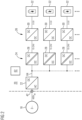
- FIG 2 shows a schematic block diagram of a first device 20 for forming rechargeable battery cells 32.
- the device 20 uses a three-stage approach for electrically coupling the battery cells 32 to an energy source, which in this embodiment provides a three-phase AC voltage network 18.
- an energy source which in this embodiment provides a three-phase AC voltage network 18.
- it is a public energy supply network in which each phase voltage of the AC voltage network 18 is approximately 230 V at approximately 50 Hz.
- the three phase voltages are each phase-shifted by 120° with respect to one another.
- the device 40 has an energy source connection 42 for electrically connecting the respective phases of the multi-phase AC voltage network 18.
- the energy source connection 42 has phase connections 44, 46, 48, which can each be electrically coupled to a phase of the three-phase AC voltage network 18 ( FIG 4 ).
- the device 20 further comprises an AC/DC converter 22, the alternating voltage side of which is connected to the phase connections 44, 46, 48.
- the AC/DC converter 22 here supplies a direct voltage in a range from approximately 600 V to approximately 800 V. This direct voltage is provided on a direct voltage network 64.
- the AC/DC converter 22 is designed to implement bidirectional energy conversion. It is thus possible to exchange electrical energy between the alternating voltage network 18 and the direct voltage network 64.
- a first converter stage 24 with galvanically isolating DC/DC converters 28 is connected to the DC voltage network 64.
- the DC/DC converters 28 are also bidirectional in terms of energy coupling.
- Each DC/DC converter 28 couples the DC voltage network 64 and provides a low voltage as a DC voltage that is in a range from about 10 V to about 24 V.
- a second converter stage 26, which has a DC/DC converter 30, is connected to the first converter stage 24.
- a respective DC/DC converter 30 is connected to each DC/DC converter 28 on the low-voltage side. This provides a charging or discharging voltage for a battery cell 32 to be connected to it.
- the DC/DC converter 30 also enables a bidirectional energy exchange, namely between the respective DC/DC converter 28 and the respective battery cell 32.
- a pair of a DC/DC converter 28 and a DC/DC converter 26 is thus provided.
- the first converter stage 24 can also be integrated into the AC/DC converter 22, so that one converter stage can be saved.
- the various converters 22, 28, 30 are controlled accordingly by a control unit 62 of the device 20. It is not shown that the respective states of the battery cells 32 can be detected by means of current and/or voltage sensors. This can be taken into account for the control of the respective converters 22, 28, 30. The converters 22, 28, 30 are controlled accordingly by the control unit 62.
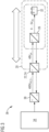
- FIG 3 shows in a schematic representation a further embodiment based on the construction according to FIG 2 based, which is why reference is made to the corresponding previous explanations.
- the AC/DC converter 22 also performs the function of the first converter stage 24 from FIG 2 with, which is why a direct voltage network with a direct voltage of about 48 V is provided on the direct voltage side.
- the DC/DC converters 26 are connected to this direct voltage network, each of which can be electrically connected to a respective battery cell 32.
- the device 20 is connected via a three-phase transformer 38 to an electrical energy source 36, which in the present case provides a three-phase alternating voltage network, which is operated with medium voltage in a range of about 3 kV to about 36 kV.
- the transformer 38 is connected to the alternating voltage network on the primary side and provides a three-phase AC voltage is available, as can be seen from FIG 2 with reference to the AC network 18.
- an efficiency of approximately 82% can be achieved with regard to a charging process of battery cells 32.
- An efficiency of approximately 81% can be achieved for the return of energy to the AC voltage network 34, for example in the area of recuperation. This is indicated by the wide double arrow in FIG 3 shown.
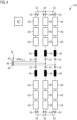
- a second device 40 which also serves to form rechargeable battery cells 32 using the energy source.
- the energy source provides - as in the first device 20 - a three-phase AC voltage network 18.
- the device 40 also has an energy source connection 42 for electrically connecting respective phases of the three-phase AC voltage network 18, wherein the energy source connection 42 has a respective phase connection 44, 46, 48 for each phase.
- the device 40 also has six forming series circuits 50, each of which has a first and a second circuit connection 52, 54.
- the circuit connections 52, 54 of a respective forming series circuit 50 are each connected to a series circuit comprising a series circuit inductance 56 and a plurality of forming modules 60 as well as an auxiliary module 58.
- Each phase terminal 44, 46, 48 is electrically coupled to the respective first circuit terminal 52 of at least one of the forming series circuits 50.
- the respective second circuit terminals 54 of such formation series circuits 50 whose first circuit terminals 52 are each electrically coupled to a different one of the phase terminals 44, 46, 48, are electrically connected to one another. In this way, two star circuits are created.
- the circuit structure is shown in FIG 4 shown.
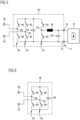
- FIG 5 shows a schematic circuit diagram of a forming module 60 as used in the forming series circuits 50 in FIG 4 is used.
- the forming module 60 has a cell connection 74 for detachable electrical connection to a respective battery cell 32, wherein the cell connection 74 has a first and a second cell connection contact 76, 78.
- the forming module 60 has two module connections 80, 82 for electrical coupling to the electrical energy source.
- the module connections 80, 82 serve to implement the respective forming series circuit 50.
- the forming module 60 also has two first series circuits 84 each comprising two switching elements 86.
- the two first series circuits 84 are connected in parallel.
- the two first series circuits 84 each have a center connection 88, 90.
- One of the center connections 88, 90 is electrically coupled to one of the module connections 80, 82.
- One end of the first series circuits 84 is electrically coupled to the first cell connection contact 76.
- the switching elements 86 are of the same design.
- the forming module 60 further comprises a second series circuit 92 comprising two series-connected switching elements 86 which substantially correspond to the switching elements 86 of the first series circuits 84.
- the second series circuit 92 is electrically coupled in parallel with the two first series circuits 84.
- a center terminal 94 of the second series circuit 92 is electrically coupled to the second cell terminal 78.
- the switching elements 86 are formed in the present case by transistors that are operated in switching mode. Each of the transistors has an inverse diode (not shown) that is connected in parallel internally in each transistor. However, the invention is not limited to this type of switching element. In principle, it could also be used with other suitable electronic switching elements. In the present case, it is provided that the transistors are formed by appropriately designed IGBTs. A design using MOSFETs can also be provided.
- a capacitor 96 is also connected in parallel to the series circuits 84, 92. Furthermore, the electrical coupling between the second cell connection contact 78 and the center connection 94 of the second series circuit 92 has an electrical module inductance 98. A capacitor 100 is also connected to the cell connection contacts 76, 78.
- This construction makes it possible to achieve a converter functionality such as that achieved by means of the DC/DC converter 30 of the device 20 according to FIG 2 can be realized.
- the converter functionality formed in this way can be operated to realize a bidirectional energy flow, i.e. the battery cell 32 can be both charged and discharged.
- the converter functionality can be realized, for example, as a boost converter or as a buck converter, depending on requirements.
- the basic function of the converter functionality is known to the person skilled in the art, which is why detailed explanations are not provided.
- FIG 6 shows an auxiliary module 58, the design and functionality of which is based on the formation module 60, which is why additional reference is made to the relevant explanations.
- the auxiliary module 58 differs from the forming module 60 in that it only has the first series circuits 84 and the capacitor 96. A battery cell 32 cannot be connected to the auxiliary module 58.
- each of the series circuits 50 has an auxiliary module 58 in addition to the series circuit of the series circuit inductance 56 and the forming modules 60.
- the series circuit of the modules 58, 60 is carried out using the module connections 80, 82.
- the modules 58, 60 are coupled to the control unit 62 in terms of signals, so that the switching states of the switching elements 86 can be set as required using the control unit 62.
- the auxiliary module 58 is preferably provided optionally and can, under certain circumstances, advantageously compensate for unfavorable conditions in relation to the mains voltage and a number of forming modules.
- the forming modules 60 in the area of the cell connection 74 can detect a cell voltage of the battery cell 32 in the connected state by means of a voltage sensor.
- a current sensor is also provided, by means of which a cell current of the battery cell 32 can be detected.
- Corresponding sensor signals are transmitted to the control unit 62 via a communication connection (not shown). This makes it possible for the control unit 62 to determine, among other things, a state of the battery cell 32 and/or to determine whether a battery cell 32 is connected to the corresponding forming module 60.
- FIG 7 shows an alternative embodiment for a circuit structure of the device 40, in which each phase connection 44, 46, 48 is electrically coupled to the second circuit connection 54 of one of the formation series circuits 50 whose first circuit connection 52 is coupled to another of the phase connections 44, 46, 48. Since it In the present case, it is provided that the AC voltage network 18 is a three-phase AC voltage network, the circuit structure of a delta connection is implemented. However, this is not limiting for the function of the invention.
- the formation series circuits 50 which in FIG 7 Of course, further formation series circuits 50 can also be connected in parallel without departing from the spirit of the invention. Regarding the further features and functions, reference is made to the corresponding statements above, in particular to the device 40 according to FIG 4 , referred to.
- FIG 8 shows a schematic representation of a specific structure as can be implemented for the forming device 40. It can be seen that forming modules 60 are arranged in several stacks next to one another. These are arranged in the manner of an n-gon, at least in sections. An arrangement device 70 with a robot 72 is provided centrally, which provides a cell gripping arm 68. The cell gripping arm 68 is designed to be electrically insulated.
- the cell gripper arm 68 and the robot 72 it is possible to equip the formation modules 60 with battery cells 32 as required or to remove battery cells 32 from the formation modules 60 for which the formation process has been completed. This makes it possible to create a highly efficient device 40 that makes it possible to make almost any change to the configuration of the battery cells 32 during normal operation.
- the electrically insulating design of the cell gripper arm 68 means that requirements with regard to electrical safety can be implemented in a simple manner.
- each formation module 60 has a housing 102.
- the housing 102 provides a cell receptacle 66.
- the cell connection 74 is formed in the area of the cell holder 66. This allows by simply inserting a Battery cell 32 in the cell holder 66, a detachable electrical connection with the forming module 60 can be automatically established. For this purpose, corresponding contact pins or contact springs or the like can be provided.
- the formation series circuits 50 do not necessarily have to have an auxiliary module 58. If necessary, the control 62 must be adapted accordingly.
Landscapes
- Engineering & Computer Science (AREA)
- Chemical & Material Sciences (AREA)
- Chemical Kinetics & Catalysis (AREA)
- Electrochemistry (AREA)
- General Chemical & Material Sciences (AREA)
- Manufacturing & Machinery (AREA)
- Power Engineering (AREA)
- Physics & Mathematics (AREA)
- Electromagnetism (AREA)
- Microelectronics & Electronic Packaging (AREA)
- Charge And Discharge Circuits For Batteries Or The Like (AREA)
Priority Applications (1)
| Application Number | Priority Date | Filing Date | Title |
|---|---|---|---|
| EP23192684.1A EP4513698A1 (fr) | 2023-08-22 | 2023-08-22 | Formation de cellules de batterie rechargeables au moyen d'une source d'énergie |
Applications Claiming Priority (1)
| Application Number | Priority Date | Filing Date | Title |
|---|---|---|---|
| EP23192684.1A EP4513698A1 (fr) | 2023-08-22 | 2023-08-22 | Formation de cellules de batterie rechargeables au moyen d'une source d'énergie |
Publications (1)
| Publication Number | Publication Date |
|---|---|
| EP4513698A1 true EP4513698A1 (fr) | 2025-02-26 |
Family
ID=87762991
Family Applications (1)
| Application Number | Title | Priority Date | Filing Date |
|---|---|---|---|
| EP23192684.1A Withdrawn EP4513698A1 (fr) | 2023-08-22 | 2023-08-22 | Formation de cellules de batterie rechargeables au moyen d'une source d'énergie |
Country Status (1)
| Country | Link |
|---|---|
| EP (1) | EP4513698A1 (fr) |
Citations (5)
| Publication number | Priority date | Publication date | Assignee | Title |
|---|---|---|---|---|
| DE102010013862A1 (de) * | 2010-04-01 | 2011-10-06 | Gottfried Wilhelm Leibniz Universität Hannover | Transformatorloser Direktumrichter |
| DE102014219789A1 (de) | 2014-09-30 | 2016-03-31 | Siemens Aktiengesellschaft | Modularer Multilevelumrichter mit zentralem Kondensator am Zwischenkreis |
| DE102014225287A1 (de) | 2014-12-09 | 2016-06-09 | Siemens Aktiengesellschaft | Mehrpegelenergiewandler |
| DE102015205267A1 (de) | 2015-03-24 | 2016-09-29 | Siemens Aktiengesellschaft | Wandlermodul für einen Mehrpegelenergiewandler |
| US20180294657A1 (en) * | 2017-04-06 | 2018-10-11 | Tesla, Inc. | System and method for facilitating conditioning and testing of rechargeable battery cells |
-
2023
- 2023-08-22 EP EP23192684.1A patent/EP4513698A1/fr not_active Withdrawn
Patent Citations (5)
| Publication number | Priority date | Publication date | Assignee | Title |
|---|---|---|---|---|
| DE102010013862A1 (de) * | 2010-04-01 | 2011-10-06 | Gottfried Wilhelm Leibniz Universität Hannover | Transformatorloser Direktumrichter |
| DE102014219789A1 (de) | 2014-09-30 | 2016-03-31 | Siemens Aktiengesellschaft | Modularer Multilevelumrichter mit zentralem Kondensator am Zwischenkreis |
| DE102014225287A1 (de) | 2014-12-09 | 2016-06-09 | Siemens Aktiengesellschaft | Mehrpegelenergiewandler |
| DE102015205267A1 (de) | 2015-03-24 | 2016-09-29 | Siemens Aktiengesellschaft | Wandlermodul für einen Mehrpegelenergiewandler |
| US20180294657A1 (en) * | 2017-04-06 | 2018-10-11 | Tesla, Inc. | System and method for facilitating conditioning and testing of rechargeable battery cells |
Similar Documents
| Publication | Publication Date | Title |
|---|---|---|
| EP2424747B1 (fr) | Véhicule électrique | |
| EP4087087A2 (fr) | Système d'alimentation électrique | |
| EP3501884A1 (fr) | Dispositif transformateur pour une station de charge destiné à la charge électrique de véhicules au moyen d'au moins deux points de charge | |
| EP2467927A1 (fr) | Procédé permettant de décharger un condensateur de circuit intermédiaire d'un convertisseur de tension à circuit intermédiaire | |
| DE102012205395A1 (de) | Batteriesystem, Verfahren zum Laden von Batteriemodulen, sowie Verfahren zum Balancieren von Batteriemodulen | |
| DE102010038880A1 (de) | Energiewandler zum Ausgeben elektrischer Energie | |
| DE102019106485A1 (de) | Weissach-Gleichrichteranordnung | |
| EP3467990A1 (fr) | Dispositif de fourniture d'énergie destiné à fournir de l'énergie électrique à au moins un terminal ainsi que procédé de fonctionnement d'un dispositif de fourniture d'énergie | |
| DE102014212935A1 (de) | Vorrichtung zum Bereitstellen einer elektrischen Spannung mit seriellem Stack-Umrichter sowie Antriebsanordnung | |
| DE102019005621A1 (de) | Bordnetz für ein elektrisch antreibbares Kraftfahrzeug | |
| WO2021078518A1 (fr) | Système électrique de véhicule | |
| DE102015007264B4 (de) | Schnelles Übertragen von elektrischer Energie von einer Ladestation zu einem Verbraucher | |
| EP3501885A1 (fr) | Module électronique de puissance pour une station de charge ainsi que station de charge et station service électrique correspondantes | |
| DE102017220599A1 (de) | Umrichteranordnung zum Stabilisieren eines Wechselspannungsnetzes | |
| EP2733837A1 (fr) | Convertisseur | |
| EP4513698A1 (fr) | Formation de cellules de batterie rechargeables au moyen d'une source d'énergie | |
| DE102017203233A1 (de) | Modularer Wechselrichter | |
| DE102019212000A1 (de) | Batterieschaltung zum Einstellen von Ladungszuständen von Batterieelementen sowie Verfahren zum Betreiben einer Batterieschaltung | |
| DE102020213227B3 (de) | Ladeschaltung mit einem Gleichstromanschluss und einem Wechselstromanschluss sowie Bordnetz mit einer Ladeschaltung | |
| DE102014100257A1 (de) | Modularer Umrichter und Energieübertragungseinrichtung | |
| DE102010042718A1 (de) | Verfahren zur Steuerung einer Batterie mit variabler Ausgangsspannung | |
| DE102022210657A1 (de) | Elektrische Schaltung für ein Hochvoltnetz eines Fahrzeugs | |
| DE102012214097A1 (de) | Formierungsvorrichtung und Verfahren zur Formierung von Batteriezellen einer Batterie | |
| DE102018004109A1 (de) | Batterie zum reversiblen elektrochemischen Speichern von elektrischer Ladung | |
| DE102024002035B3 (de) | Elektrisches Antriebssystem und Verfahren zum Laden |
Legal Events
| Date | Code | Title | Description |
|---|---|---|---|
| PUAI | Public reference made under article 153(3) epc to a published international application that has entered the european phase |
Free format text: ORIGINAL CODE: 0009012 |
|
| STAA | Information on the status of an ep patent application or granted ep patent |
Free format text: STATUS: THE APPLICATION HAS BEEN PUBLISHED |
|
| AK | Designated contracting states |
Kind code of ref document: A1 Designated state(s): AL AT BE BG CH CY CZ DE DK EE ES FI FR GB GR HR HU IE IS IT LI LT LU LV MC ME MK MT NL NO PL PT RO RS SE SI SK SM TR |
|
| STAA | Information on the status of an ep patent application or granted ep patent |
Free format text: STATUS: THE APPLICATION IS DEEMED TO BE WITHDRAWN |
|
| 18D | Application deemed to be withdrawn |
Effective date: 20250827 |