EP4513704A1 - Système de collecte d'énergie sous-marin comprenant un agencement de transformateur distribué - Google Patents
Système de collecte d'énergie sous-marin comprenant un agencement de transformateur distribué Download PDFInfo
- Publication number
- EP4513704A1 EP4513704A1 EP23193494.4A EP23193494A EP4513704A1 EP 4513704 A1 EP4513704 A1 EP 4513704A1 EP 23193494 A EP23193494 A EP 23193494A EP 4513704 A1 EP4513704 A1 EP 4513704A1
- Authority
- EP
- European Patent Office
- Prior art keywords
- power
- collection system
- phase
- substation
- output point
- Prior art date
- Legal status (The legal status is an assumption and is not a legal conclusion. Google has not performed a legal analysis and makes no representation as to the accuracy of the status listed.)
- Pending
Links
Images




Classifications
-
- H—ELECTRICITY
- H02—GENERATION; CONVERSION OR DISTRIBUTION OF ELECTRIC POWER
- H02J—ELECTRIC POWER NETWORKS; CIRCUIT ARRANGEMENTS OR SYSTEMS FOR SUPPLYING OR DISTRIBUTING ELECTRIC POWER; SYSTEMS FOR STORING ELECTRIC ENERGY
- H02J3/00—Circuit arrangements for AC mains or AC distribution networks
- H02J3/38—Arrangements for feeding a single network from two or more generators or sources in parallel; Arrangements for feeding already energised networks from additional generators or sources in parallel
- H02J3/381—Dispersed generators
-
- F—MECHANICAL ENGINEERING; LIGHTING; HEATING; WEAPONS; BLASTING
- F03—MACHINES OR ENGINES FOR LIQUIDS; WIND, SPRING, OR WEIGHT MOTORS; PRODUCING MECHANICAL POWER OR A REACTIVE PROPULSIVE THRUST, NOT OTHERWISE PROVIDED FOR
- F03D—WIND MOTORS
- F03D9/00—Adaptations of wind motors for special use; Combinations of wind motors with apparatus driven thereby; Wind motors specially adapted for installation in particular locations
- F03D9/20—Wind motors characterised by the driven apparatus
- F03D9/25—Wind motors characterised by the driven apparatus the apparatus being an electrical generator
- F03D9/255—Wind motors characterised by the driven apparatus the apparatus being an electrical generator connected to electrical distribution networks; Arrangements therefor
-
- B—PERFORMING OPERATIONS; TRANSPORTING
- B63—SHIPS OR OTHER WATERBORNE VESSELS; RELATED EQUIPMENT
- B63B—SHIPS OR OTHER WATERBORNE VESSELS; EQUIPMENT FOR SHIPPING
- B63B35/00—Vessels or similar floating structures specially adapted for specific purposes and not otherwise provided for
- B63B35/44—Floating buildings, stores, drilling platforms, or workshops, e.g. carrying water-oil separating devices
- B63B2035/4433—Floating structures carrying electric power plants
- B63B2035/446—Floating structures carrying electric power plants for converting wind energy into electric energy
-
- F—MECHANICAL ENGINEERING; LIGHTING; HEATING; WEAPONS; BLASTING
- F05—INDEXING SCHEMES RELATING TO ENGINES OR PUMPS IN VARIOUS SUBCLASSES OF CLASSES F01-F04
- F05B—INDEXING SCHEME RELATING TO WIND, SPRING, WEIGHT, INERTIA OR LIKE MOTORS, TO MACHINES OR ENGINES FOR LIQUIDS COVERED BY SUBCLASSES F03B, F03D AND F03G
- F05B2240/00—Components
- F05B2240/90—Mounting on supporting structures or systems
- F05B2240/95—Mounting on supporting structures or systems offshore
-
- H—ELECTRICITY
- H02—GENERATION; CONVERSION OR DISTRIBUTION OF ELECTRIC POWER
- H02J—ELECTRIC POWER NETWORKS; CIRCUIT ARRANGEMENTS OR SYSTEMS FOR SUPPLYING OR DISTRIBUTING ELECTRIC POWER; SYSTEMS FOR STORING ELECTRIC ENERGY
- H02J2101/00—Supply or distribution of decentralised, dispersed or local electric power generation
- H02J2101/20—Dispersed power generation using renewable energy sources
- H02J2101/28—Wind energy
Definitions
- the present disclosure relates to the field of offshore power generation.
- it proposes a power collection system which thanks to a distributed transformer arrangement can be given an increased output power rating.
- the offshore wind power generation market is on the rise.
- the worldwide wind power capacity is expected to increase by about 12 GW per year, reaching a total of 150 GW installed power by 2027.
- Much of the ongoing research efforts are directed at upscaling, including higher power ratings and larger installations.
- the wind turbines are getting larger, with typical unit sizes being expected to reach the range of 15-20 MW.
- a shift from fixed-support wind turbines to floating wind turbines is about to take off.
- Floating installations seem to be best suited for realizing large-scale offshore wind parks, indeed, since they are less dependent on the availability of a favorable seabed topography and can be localized further from the shoreline where the richest wind resources are.
- a power collection system refers to the cabling and components responsible for collecting the electric power generated by a park of floating wind turbines and for making it suitable for transmission and/or later use by a power consumer. For example, a number of electric power contributions collected at an intermediate voltage (e.g., 66 kV) may be combined and up-transformed (e.g., to 245 kV), and then conveyed to an onshore grid through a transmission cable.
- the power collection system may be a subsea system (i.e., which rests on the seabed) or a floating power collection system. Subsea power collection systems are easier to maintain as they operate in more stable environmental conditions, and they only exceptionally need to be connected by dynamic transmission cables. Early results suggest that this category of power collection systems is more robust and incurs a more limited capital expenditure than floating ones.
- One problem is thus to propose technology that enables the further upscaling of subsea power collection systems.
- the power collection system comprises a three-phase subgrid and a subsea power substation.
- the subgrid has a plurality of power input points towards the power generation units and a three-phase power output point, which is shared by the power input points.
- the power output point of the subgrid may correspond to a connector, interface or another physical feature of the subgrid, or it may be an entirely conceptual point on a cable in the subgrid.
- the power substation is connected to the power output point, wherein a secondary side of the power substation is arranged to be connected to a power consumer.
- the power substation comprises three one-phase transformers, which are contained in respective housings, wherein each housing is arranged to rest on the seabed and to be liftable to the sea surface separately from the other housings (i.e., after disconnecting any cables to the other housings if necessary), and each phase of the power output point is connected to a primary side of a corresponding one of the one-phase transformers.
- each one-phase transformer can be designed with a weight in the weight range that is liftable using conventional offshore technology, and with a power rating that does not require specialized cooling arrangements. Further, thanks to the relatively simpler constitution of the one-phase transformers, the lower total lifecycle cost of three one-phase transformers need not exceed that of a monolithic three-phase transformer with an equal power rating.
- arrays of wind turbines are arranged sequentially on respective three-phase cables (array cables) in the subgrid, which lead up to the three one-phase transformers. Identical phases from different array cables are connected inside the respective subsea transformer. This advantageously avoids the ampacity limitations for subsea wet-mate connectors.
- the transformer windings of the three one-phase transformers - when considered together - are star-connected on the primary side and delta-connected on the secondary side.
- power jumpers across the three transformers may optionally be provided.
- a star connection may be referred to as a Y ('wye') connection.
- the transformer windings are star-connected on the primary side and star-connected on the secondary side.
- an unloaded delta-connected tertiary winding may be arranged to suppress high-order harmonics.
- the term "power consumer” is used in an abstract (or black-box) sense and from the perspective of the subsea power substation. Accordingly, it covers not only devices which themselves dissipate electric power, but also devices that convert electric power, including a transmission cable (or export cable), an onshore substation, an offshore or onshore energy storage device, an offshore or onshore hydrogen converter, and the like.
- Figure 1 is a schematic drawing of a power collection system 100 arranged between a number of offshore power generation units 110 and a power consumer 170. A similar power collection system 100 is depicted in figure 9 .
- the power collection system 100 comprises a three-phase subgrid 120 with a plurality of power input points 121 towards the power generation units 110 and a three-phase power output point 122.
- the offshore power generation units 110 may include floating or fixed-support devices, such as one or more (floating) wind turbines, (floating) solar cell arrangements, (floating) wave energy converters, or combinations of one or more of these. Fixed-support devices may alternatively be described as bottom-fixed devices.
- the power generation units 110 may be configured to generate three-phase electric power, such that each is connected to all three phases of the subgrid 120. Alternatively, the power generation units 110 may be configured to generate one-phase electric power, wherein three subgroups of the power generation units 110 may be connected to the three phases in an approximately balanced way.
- the power input points 121 are three-phase power input points.
- the power generation units 110 may include units with a rated output power of the order of 1 MW or more, such as output power in the range of 15-20 MW or more.
- the power generation units 110 may be of a uniform type with equal power ratings, or they may have different power ratings. In the case of large-scale floating wind turbines, the mutual spacing of the power generation units 110 may be of the order of 1 km, such as 2 km or more.
- the power output point 122 is shared by the power input points 121 in the sense that a combined current representing all electric power fed into the power input points 121 is available by establishing a connection at the power output point 122 and/or in the sense that a device connected to the power output point 122 has no way of selecting a certain power input point 121 and receive electric power only from this. It is noted that the power input points 121 and power output point 122 may correspond to a physical component or another structural feature of the subgrid 120, but that such correspondence is not necessarily present. Rather, one or more of the power input points 121 and power output point 122 may be purely conceptual.
- a power input point 121 may be constituted by a connection point which is common to two or more power generation units 110.
- the power collection system 100 further comprises a subsea power substation 130, which includes three one-phase transformers 140.
- Each one-phase transformer 140 is contained in a respective housing 143 (or tank), which is arranged to rest on the seabed 102 (see figure 9 ) and with such constitution that the housing 143 with the transformer 140 inside can be lifted to the sea surface 101 (see figure 9 ) separately from the other housings.
- the ability for each housing 143 to be separately liftable implies that the three housings 140 are not permanently joined to form a rigid unit.
- these joining elements should either be long enough to allow the two housings 140 to be separated by a sufficient distance for lifting (i.e., at least the sea depth at the location of deployment), or the joining elements should be releasable non-destructively.
- the housings 140 are joined by a locking arrangement, the locking arrangement can be released non-destructively.
- the weight of a housing 140 with a one-phase transformer 140 inside is preferably less than 300 t, such as less than 200 t, such as less than 100 t.
- the housings 143 are designed to be watertight in seabed conditions, i.e., they are equipped with seals that withstand the hydrostatic pressure at the level of the seabed, and they are manufactured from materials suitable for long-term use in seawater.
- a representative depth may be 100 m or more, such as 200 m or more, such as 300 m or more, such as 500 m or more, such as 1000 m or more.
- the housings 143 may be specified for operation at a maximum depth of the order of 1500 m.
- Each of the transformers 140 has a primary side 141 corresponding to a primary winding, and a secondary side 142 corresponding to a secondary winding. In steady-state operation, net power generally flows from the primary side 141 to the secondary side winding 142.
- the orientation of the primary sides 141 and secondary sides 142 of the transformers 140 defines a primary side 131 and a secondary side 132 of the power substation 130.
- the primary side 131 of the power substation 130 interfaces with the power output point 122 of the subgrid 120, and the secondary side 132 is to be connected to the power consumer 170.
- Each of the one-phase transformers 140 may be configured for a secondary voltage of 200 kV or more, such as 245 kV.
- the primary voltage equal to the phase voltage of the subgrid 120, may for example be 60 kV or 66 kV.
- the power rating of the power collection system 100 which corresponds to the combined power rating of the transformers 140, may be 400 MVA or more, such as 600 MVA, and possibly up to 900 MVA.
- the unit designated as a power consumer 170 acts as a consumer from the perspective of the subsea power substation 130.
- the power consumer 170 may perform energy conversion itself or may facilitate energy conversion in an entity further downstream.
- the power consumer 170 may for example be a static or dynamic transmission cable (or export cable), an onshore power substation, an offshore or onshore energy storage device (e.g., battery), an offshore or onshore hydrogen converter, and the like.
- the power consumer 170 is configured to be supplied with three-phase electric power.
- the outputs of the three secondary windings 142 are directly connected to the power consumer 170.
- the outputs of the three secondary windings 142 are joined into a three-phase interface - e.g., by mechanically joining three one-phase cables into a three-phase cable or connector - and then connected to the power consumer 170.
- a dynamic sea cable is a cable designed for repeated deformations and/or mechanical loading and unloading.
- dynamic sea cables differ from equivalent static sea cable by having a better resistance to material fatigue caused by deformation.
- the power output point 122 for its part, may be constituted by a connection box which has two incoming subgrid cables from the subgrid 120, as well as three outgoing phases which continue into housings 143a, 143b, 143c that contain respective one-phase transformers (not shown) within the power substation 130.
- the outputs of the transformer which constitute the output phases of the power substation 130, leave the housings 143a, 143b, 143c and are joined at a connection box 171 into a three-phase transmission cable (or export cable) 170.
- the connection boxes 121, 122, 171, the housings 143a, 143b, 143c and the cables of the subgrid 120 are all arranged to rest on the seabed. This may include suitable technical measures for achieving chemical compatibility with seawater and/or watertightness.
- the seabed environment is a relatively stable one, the seabed-located units of the power collection system 100 do not necessarily possess a verified resistance to repeated movements during the lifecycle, as is normally required from floating generators that are exposed to waves, dynamic cables that deform to follow the sea heave, etc.
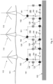
- Figure 2 shows a detail of a power collection system 100 and a number of connected offshore power generation units 110.
- the subgrid 120 is structured around N array cables 123a, 123b, 123c, which extend radially from the power output point 122, wherein the power input points 121 are arranged along the array cables 123.
- the subgrid further comprises a plurality of trunk switches 165 allowing the outer portion of the respective array cable 123 to be disconnected from the subgrid. It is not necessary to provide a trunk switch 165 outside the outermost power input point 121, although this may occur as a result of implementing the power collection system 100 as a combination of pre-designed building blocks.
- each of these is a three-phase cable, and they are not in a one-to-one relationship with the three one-phase transformers 140.
- each phase is split from the other phases of that array cable 123 so as to be joined with identical phases from the N - 1 other array cables and directed to a corresponding one of the one-phase transformers 140.
- the joined N identical phases from the array cables are connected (electrically connected) at a point inside the housing 143 that contains the corresponding one of the one-phase transformers 140.
- connection point inside the housing 143 may be a busbar, and a conventional 200 MVA transformer would have sufficient space to accommodate multiple high-voltage power feedthroughs. Thanks to the fact that the joined N identical phases from the array cables 123 are connected inside the housing 143, away from the seawater, the ampacity limitations for subsea wet-mate connectors can be circumvented.
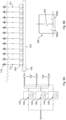
- FIGs 3 and 4 illustrates possible placements of switches 150 between the one-phase transformers and the three-phase subgrid of the power collection system.
- the switches 150 which may be used for isolating faults, are arranged between the primary side 141 of each one-phase transformer 140 and the power output point 122.
- the switches 150 are arranged on the inputs to the one-phase transformers 140, corresponding to respective phases u, v, w of the subsea power station 130.
- the switches are implemented as a dedicated switch unit 150 separate from the housings 143.
- the switches 150 are arranged inside the respective housings 143.
- a possible schematic of a one-phase switch 150 for this purpose is suggested at the top right corner of figure 3 .
- the one-phase switch is composed of two sub-switches 151, 152 which are arranged between two feedthroughs 153, 154 allowing the input to the one-phase transformer 140 to enter and leave the housing of the switch unit 150.
- the second sub-switch 152 can be set in a ground position or a closed position. In normal operation, both sub-switches 151, 152 are closed. When one or both sub-switches 151, 152 are open, the corresponding one-phase transformer 140 is disconnected from the subgrid, and the one-phase transformer 140 is optionally grounded.
- a simpler implementation of the one-phase switch 150 may include a single sub-switch.
- FIG. 5 shows a detail of a power collection system 100 in which serially connected subsea power extender modules 160 are used for connecting the offshore power generation units 110 to an array cable 123 of the subgrid 120.
- the power extender modules 160 can be understood as a modular way of providing the branch switches 164 and trunk switches 165 introduced above with reference to figure 2 .
- a power extender module 160 comprises a switchable input terminal 162 arranged to be connected to a power generation unit 110, and at least two interconnection terminals 163, suitable for connecting the power extender module 160 in series to adjacent power extender modules.
- the power extender module 160 may further comprise a connection to a data network 128, on which it may exchange protection and control related information with other components of the power collection system 100.
- the data network 128 maybe a digital packet-switched network, such as an ethernet network.
- the power extender module 160 is arranged to rest on the seabed 102 and therefore has a housing 161 designed to be watertight in seabed conditions.
- the power extender module's 160 input terminal 162 connected to the power generation unit 110 is switchable by means of switching circuitry constituting a branch switch 164, whereby the power generation unit 110 can be decoupled as desired.
- the interconnection terminal 163 is switchable too, namely, by means of switching circuitry constituting a trunk switch 165, which allows it to decouple an adjacent power extender module.
- the power extender module 160 includes two trunk switches 165a, 165b, one on each side of the branch switch 164. The availability of two trunk switches 165a, 165b which are switchable independently of one another allows fault isolation with an even finer granularity.
- Figure 6A shows a way of arranging the power extender modules 160 serially on an array cable 123 of the subgrid.
- the array cable has a ring topology, so that each power generation unit 110 sits on a loop that has two paths to the power output point 122, which allows many options for fault isolation.
- the subgrid further comprises switches 150 between the power output point 122 and each array cable 123. More precisely, there is an independent switch 150 between each end of the loop-shaped array cable 123 and the power output point 122.
- figure 6A contains multiple instances of reference number 122, which refer to galvanically connected points of the power collection system 110 which can collectively be identified as the power output point of the subgrid.
- figure 6B shows an alternative configuration of the power extender module 160, which can replace one or more of the power extender modules 160 seen in figure 6A .
- Figure 7 shows an embodiment of the subsea power substation 130 where the windings 144 of the one-phase transformers 140 are star-connected on the primary side 131 and star-connected on the secondary side 132. It is understood that the two windings 144 inside each of the three housings 140 are magnetically coupled. This embodiment is relatively simple and inexpensive to manufacture and install. Neutral points 146 on both the primary and secondary side can be solidly grounded inside the housing 143. To attenuate third- and higher-order harmonics, an unloaded delta-connected tertiary winding can be added to the circuit shown in figure 7 .
- FIG 8 shows an embodiment where the windings 144 of the one-phase transformers are delta-connected on the primary side and star-connected on the secondary side.
- power jumpers 145 each of which is an electric connection provided between pairs of the one-phase transformers 140. At least one segment of each power jumper 145 is provided as a sea cable.
- each power jumper 145 is permanently connected to one one-phase transformer 140 and arranged to be connected to a further one-phase transformer 140 when the two transformers 140 have been deployed (pigtail configuration).
- the connection to the further one-phase transformer 140 is releasable, i.e., it can be undone non-destructively.
- each pair of one-phase transformers 140 may be connected by multiple power jumpers 145 in parallel.
Landscapes
- Engineering & Computer Science (AREA)
- Power Engineering (AREA)
- Life Sciences & Earth Sciences (AREA)
- Sustainable Development (AREA)
- Sustainable Energy (AREA)
- Chemical & Material Sciences (AREA)
- Combustion & Propulsion (AREA)
- Mechanical Engineering (AREA)
- General Engineering & Computer Science (AREA)
- Supply And Distribution Of Alternating Current (AREA)
- Other Liquid Machine Or Engine Such As Wave Power Use (AREA)
Priority Applications (5)
| Application Number | Priority Date | Filing Date | Title |
|---|---|---|---|
| EP23193494.4A EP4513704A1 (fr) | 2023-08-25 | 2023-08-25 | Système de collecte d'énergie sous-marin comprenant un agencement de transformateur distribué |
| AU2024330912A AU2024330912A1 (en) | 2023-08-25 | 2024-03-07 | A subsea power collection system including a distributed transformer arrangement |
| CN202480053098.9A CN121713347A (zh) | 2023-08-25 | 2024-03-07 | 包括分布式变压器装置的海底功率收集系统 |
| KR1020267008499A KR20260049663A (ko) | 2023-08-25 | 2024-03-07 | 분산형 변압기 장치를 포함하는 해저 전력 수집 시스템 |
| PCT/EP2024/056068 WO2025045394A1 (fr) | 2023-08-25 | 2024-03-07 | Système de collecte d'énergie sous-marin comprenant un agencement de transformateur distribué |
Applications Claiming Priority (1)
| Application Number | Priority Date | Filing Date | Title |
|---|---|---|---|
| EP23193494.4A EP4513704A1 (fr) | 2023-08-25 | 2023-08-25 | Système de collecte d'énergie sous-marin comprenant un agencement de transformateur distribué |
Publications (1)
| Publication Number | Publication Date |
|---|---|
| EP4513704A1 true EP4513704A1 (fr) | 2025-02-26 |
Family
ID=87845822
Family Applications (1)
| Application Number | Title | Priority Date | Filing Date |
|---|---|---|---|
| EP23193494.4A Pending EP4513704A1 (fr) | 2023-08-25 | 2023-08-25 | Système de collecte d'énergie sous-marin comprenant un agencement de transformateur distribué |
Country Status (5)
| Country | Link |
|---|---|
| EP (1) | EP4513704A1 (fr) |
| KR (1) | KR20260049663A (fr) |
| CN (1) | CN121713347A (fr) |
| AU (1) | AU2024330912A1 (fr) |
| WO (1) | WO2025045394A1 (fr) |
Citations (6)
| Publication number | Priority date | Publication date | Assignee | Title |
|---|---|---|---|---|
| WO2013182205A1 (fr) * | 2012-06-08 | 2013-12-12 | Vestas Wind Systems A/S | Agencement d'un appareil de commutation dans une tour d'une turbine éolienne |
| JP2015080404A (ja) * | 2013-10-17 | 2015-04-23 | シーメンス アクチエンゲゼルシヤフトSiemens Aktiengesellschaft | 洋上入力端と陸上出力端を有する海底交流送電ケーブルにおける無効電力補償 |
| JP2015192593A (ja) * | 2014-03-31 | 2015-11-02 | 株式会社トーメック | 単独運転可能高調波抑制装置 |
| WO2022194667A1 (fr) * | 2021-03-17 | 2022-09-22 | Aker Solutions As | Ensemble de distribution d'énergie de centrale électrique en mer à haute tension |
| EP4063646A1 (fr) | 2021-03-25 | 2022-09-28 | ABB Schweiz AG | Système de collecte d'énergie pour le transfert sous-marin d'énergie provenant d'unités de production d'énergie en mer |
| US20220320836A1 (en) * | 2019-09-03 | 2022-10-06 | Aker Solutions As | Offshore subsea power distribution |
-
2023
- 2023-08-25 EP EP23193494.4A patent/EP4513704A1/fr active Pending
-
2024
- 2024-03-07 WO PCT/EP2024/056068 patent/WO2025045394A1/fr active Pending
- 2024-03-07 CN CN202480053098.9A patent/CN121713347A/zh active Pending
- 2024-03-07 AU AU2024330912A patent/AU2024330912A1/en active Pending
- 2024-03-07 KR KR1020267008499A patent/KR20260049663A/ko active Pending
Patent Citations (6)
| Publication number | Priority date | Publication date | Assignee | Title |
|---|---|---|---|---|
| WO2013182205A1 (fr) * | 2012-06-08 | 2013-12-12 | Vestas Wind Systems A/S | Agencement d'un appareil de commutation dans une tour d'une turbine éolienne |
| JP2015080404A (ja) * | 2013-10-17 | 2015-04-23 | シーメンス アクチエンゲゼルシヤフトSiemens Aktiengesellschaft | 洋上入力端と陸上出力端を有する海底交流送電ケーブルにおける無効電力補償 |
| JP2015192593A (ja) * | 2014-03-31 | 2015-11-02 | 株式会社トーメック | 単独運転可能高調波抑制装置 |
| US20220320836A1 (en) * | 2019-09-03 | 2022-10-06 | Aker Solutions As | Offshore subsea power distribution |
| WO2022194667A1 (fr) * | 2021-03-17 | 2022-09-22 | Aker Solutions As | Ensemble de distribution d'énergie de centrale électrique en mer à haute tension |
| EP4063646A1 (fr) | 2021-03-25 | 2022-09-28 | ABB Schweiz AG | Système de collecte d'énergie pour le transfert sous-marin d'énergie provenant d'unités de production d'énergie en mer |
Also Published As
| Publication number | Publication date |
|---|---|
| WO2025045394A1 (fr) | 2025-03-06 |
| CN121713347A (zh) | 2026-03-20 |
| KR20260049663A (ko) | 2026-04-14 |
| AU2024330912A1 (en) | 2026-03-19 |
Similar Documents
| Publication | Publication Date | Title |
|---|---|---|
| KR102883605B1 (ko) | 해상 전력 분배 | |
| EP2713468B1 (fr) | Systèmes électriques de transmission de puissance | |
| Reed et al. | Ship to grid: Medium-voltage DC concepts in theory and practice | |
| DK2863053T3 (en) | One-piece electrical device for connecting an offshore wind turbine with an electric submarine cable and method for mounting it | |
| CN100468922C (zh) | 风力发电设备 | |
| Lundberg et al. | Platforms for change: High-voltage DC converters and cable technologies for offshore renewable integration and DC grid expansions | |
| EP2341594A1 (fr) | Systèmes de transmission et de collecte d'alimentation | |
| US12372052B1 (en) | Wave energy converter with surface electric grid | |
| Robak et al. | Substations for offshore wind farms: a review from the perspective of the needs of the Polish wind energy sector | |
| EP3512062A1 (fr) | Parc éolien et sous-station en mer | |
| Callavik et al. | Technology developments and plans to solve operational challenges facilitating the HVDC offshore grid | |
| JP7490900B2 (ja) | 洋上発電ユニットからの電力の海中伝送のための集電システム | |
| US12146472B2 (en) | High voltage offshore power plant power distribution assembly | |
| Acaroğlu et al. | An economic and technical review for the utilization of HVDC in Turkey and in the world | |
| Prousalidis et al. | The ports as smart micro-grids: development perspectives | |
| EP4513704A1 (fr) | Système de collecte d'énergie sous-marin comprenant un agencement de transformateur distribué | |
| Barker et al. | Completing the Circuit: Integration of Offshore Wind Farms into the Grid using High Voltage dc Technology | |
| US12529356B2 (en) | Wind turbine and wind farm | |
| Nilsson | High voltage electric power transmission system expansions: technology options available | |
| EP4513029A1 (fr) | Système de collecte d'énergie pour unités de production d'énergie en mer | |
| EP4657697A1 (fr) | Modules offshore pour convertir de l'énergie en mode bipolaire, système de plateforme offshore et procédé associé | |
| Prada‐Gil et al. | Offshore Wind Power Plants (OWPPS) | |
| Luis et al. | OFFSHORE WIND POWER PLANTS (OWPPS) | |
| Fang | 1c Introduction to HVDC for Offshore Wind | |
| Curvers et al. | WP 3: Technologies state of the art |
Legal Events
| Date | Code | Title | Description |
|---|---|---|---|
| PUAI | Public reference made under article 153(3) epc to a published international application that has entered the european phase |
Free format text: ORIGINAL CODE: 0009012 |
|
| STAA | Information on the status of an ep patent application or granted ep patent |
Free format text: STATUS: THE APPLICATION HAS BEEN PUBLISHED |
|
| AK | Designated contracting states |
Kind code of ref document: A1 Designated state(s): AL AT BE BG CH CY CZ DE DK EE ES FI FR GB GR HR HU IE IS IT LI LT LU LV MC ME MK MT NL NO PL PT RO RS SE SI SK SM TR |
|
| STAA | Information on the status of an ep patent application or granted ep patent |
Free format text: STATUS: REQUEST FOR EXAMINATION WAS MADE |
|
| 17P | Request for examination filed |
Effective date: 20250728 |