EP4513710A2 - Batteriespeichersystem und verfahren zur bereitstellung einer verbesserten batterielebensdauer - Google Patents
Batteriespeichersystem und verfahren zur bereitstellung einer verbesserten batterielebensdauer Download PDFInfo
- Publication number
- EP4513710A2 EP4513710A2 EP24187580.6A EP24187580A EP4513710A2 EP 4513710 A2 EP4513710 A2 EP 4513710A2 EP 24187580 A EP24187580 A EP 24187580A EP 4513710 A2 EP4513710 A2 EP 4513710A2
- Authority
- EP
- European Patent Office
- Prior art keywords
- battery
- multilevel converter
- battery module
- state
- module
- Prior art date
- Legal status (The legal status is an assumption and is not a legal conclusion. Google has not performed a legal analysis and makes no representation as to the accuracy of the status listed.)
- Pending
Links
Images




Classifications
-
- B—PERFORMING OPERATIONS; TRANSPORTING
- B60—VEHICLES IN GENERAL
- B60L—PROPULSION OF ELECTRICALLY-PROPELLED VEHICLES; SUPPLYING ELECTRIC POWER FOR AUXILIARY EQUIPMENT OF ELECTRICALLY-PROPELLED VEHICLES; ELECTRODYNAMIC BRAKE SYSTEMS FOR VEHICLES IN GENERAL; MAGNETIC SUSPENSION OR LEVITATION FOR VEHICLES; MONITORING OPERATING VARIABLES OF ELECTRICALLY-PROPELLED VEHICLES; ELECTRIC SAFETY DEVICES FOR ELECTRICALLY-PROPELLED VEHICLES
- B60L58/00—Methods or circuit arrangements for monitoring or controlling batteries or fuel cells, specially adapted for electric vehicles
- B60L58/10—Methods or circuit arrangements for monitoring or controlling batteries or fuel cells, specially adapted for electric vehicles for monitoring or controlling batteries
- B60L58/18—Methods or circuit arrangements for monitoring or controlling batteries or fuel cells, specially adapted for electric vehicles for monitoring or controlling batteries of two or more battery modules
- B60L58/19—Switching between serial connection and parallel connection of battery modules
-
- B—PERFORMING OPERATIONS; TRANSPORTING
- B60—VEHICLES IN GENERAL
- B60L—PROPULSION OF ELECTRICALLY-PROPELLED VEHICLES; SUPPLYING ELECTRIC POWER FOR AUXILIARY EQUIPMENT OF ELECTRICALLY-PROPELLED VEHICLES; ELECTRODYNAMIC BRAKE SYSTEMS FOR VEHICLES IN GENERAL; MAGNETIC SUSPENSION OR LEVITATION FOR VEHICLES; MONITORING OPERATING VARIABLES OF ELECTRICALLY-PROPELLED VEHICLES; ELECTRIC SAFETY DEVICES FOR ELECTRICALLY-PROPELLED VEHICLES
- B60L58/00—Methods or circuit arrangements for monitoring or controlling batteries or fuel cells, specially adapted for electric vehicles
- B60L58/10—Methods or circuit arrangements for monitoring or controlling batteries or fuel cells, specially adapted for electric vehicles for monitoring or controlling batteries
- B60L58/18—Methods or circuit arrangements for monitoring or controlling batteries or fuel cells, specially adapted for electric vehicles for monitoring or controlling batteries of two or more battery modules
- B60L58/21—Methods or circuit arrangements for monitoring or controlling batteries or fuel cells, specially adapted for electric vehicles for monitoring or controlling batteries of two or more battery modules having the same nominal voltage
-
- H—ELECTRICITY
- H01—ELECTRIC ELEMENTS
- H01M—PROCESSES OR MEANS, e.g. BATTERIES, FOR THE DIRECT CONVERSION OF CHEMICAL ENERGY INTO ELECTRICAL ENERGY
- H01M10/00—Secondary cells; Manufacture thereof
- H01M10/42—Methods or arrangements for servicing or maintenance of secondary cells or secondary half-cells
- H01M10/44—Methods for charging or discharging
- H01M10/441—Methods for charging or discharging for several batteries or cells simultaneously or sequentially
-
- H—ELECTRICITY
- H01—ELECTRIC ELEMENTS
- H01M—PROCESSES OR MEANS, e.g. BATTERIES, FOR THE DIRECT CONVERSION OF CHEMICAL ENERGY INTO ELECTRICAL ENERGY
- H01M10/00—Secondary cells; Manufacture thereof
- H01M10/42—Methods or arrangements for servicing or maintenance of secondary cells or secondary half-cells
- H01M10/48—Accumulators combined with arrangements for measuring, testing or indicating the condition of cells, e.g. the level or density of the electrolyte
- H01M10/482—Accumulators combined with arrangements for measuring, testing or indicating the condition of cells, e.g. the level or density of the electrolyte for several batteries or cells simultaneously or sequentially
-
- G—PHYSICS
- G01—MEASURING; TESTING
- G01R—MEASURING ELECTRIC VARIABLES; MEASURING MAGNETIC VARIABLES
- G01R31/00—Arrangements for testing electric properties; Arrangements for locating electric faults; Arrangements for electrical testing characterised by what is being tested not provided for elsewhere
- G01R31/36—Arrangements for testing, measuring or monitoring the electrical condition of accumulators or electric batteries, e.g. capacity or state of charge [SoC]
- G01R31/392—Determining battery ageing or deterioration, e.g. state of health
Definitions
- the invention relates to a battery storage system using multilevel converters and to a Method for providing an enhanced battery lifetime.
- US 2014/0049230 A1 discloses a multilevel converter topology for generating AC signals by switching multiple batteries.
- each battery management unit includes a battery cell, an isolation element, and a bypass element. This allows to activate or isolate individual battery cells.
- the problem to be solved by the invention is to provide a battery storage system, where the batteries have a longer lifetime compared to known battery storage systems. Further, a method should be provided for increasing lifetime of batteries within a battery storage system, but without interruption of the operation of the battery system.
- a method of operating a battery storage system is based on a battery storage system comprising at least one multilevel converter (MLC).
- a multilevel converter includes a plurality of battery modules, where each of the plurality of battery modules includes at least one battery.
- the at least one multi-level converter is configured for multilevel converter mode (MLC mode) including at least one of delivering electrical power by discharging at least one battery and/or receiving electrical power by charging at least one battery. This also includes that for short periods of time, e.g., when a sine wave passes zero, no battery module may be connected and such no batter is charged or discharged.
- the electrical power may be delivered to a load, e.g., a power grid, battery, motor or current consumer. Further, the electrical power may be received from a source, e.g., power grid, battery, motor/generator or power plant.
- the method comprises at least the steps of:
- the same problem is solved by performing at least the following steps.
- the at least one multilevel converter is configured for multilevel converter mode by using a subset of the plurality of batteries.
- the steps include:
- the selection of the battery modules may be made from a group of battery modules which
- step a) may be executed some time ahead steps b) and c). Prediction may be based on load of the battery system, such that step b) falls in a time with low load to the battery storage system, e.g., at night.
- the additional step max be executed before any step b).
- a string may be configured to provide balancing of its battery modules. Normally, the number N of battery modules within a string is selected, such that the string may provide a higher output voltage than its nominal output voltage. Therefore, normally, not all battery modules are required to each provide a nominal output voltage and not all battery modules are in a connected state. The remaining battery modules are in a bypass state and do not deliver power, such that only the batteries of the connected battery modules will be discharged while the batteries of the modules in bypass state keep their charge.
- the battery modules in a string may be configured to different states, e.g., from connected state to bypass state or from bypass state to connected state, such that all batteries are discharged to a common power state, e.g., state of charge.
- the battery storage system may be configured to select within a string over multiple periods of time/and or time intervals different combinations of battery modules for a connected state while the remaining battery modules are in a bypass state.
- at least one of the battery modules with a higher power state may have longer times in a connected state than at least one of the battery modules with a lower power state.
- the temperature of a battery module being in rest state may be monitored from the beginning of the rest state. The decrease in temperature may be evaluated. This may be done until the temperature change has been settled to a predetermined value.
- the battery module may have at least one temperature sensor. During the rest state, the temperature may decrease to an ambient temperature. With the information from this cooldown temperature profile a thermal model can be obtained.
- one or more further rested battery modules may be put in a connected state for short time intervals, generating pulses with sequential positive and negative pulse currents, wherein one or more of those pulses result in net zero charge transfer.
- the thermal response on a specified charge transfer can be observed and the thermal model can be calculated or verified. Based on the thermal model and the temperature increase during the energy pulses the battery health and/or internal battery losses can be estimated from measured battery temperature and/or voltage values without stopping MLC operation.
- a further embodiment relates to a method and device for controlling a multilevel converter which is connected to a power grid.
- This embodiment provides an excellent control while reducing the amount of processing power, such that the control can be implemented with comparatively simple and inexpensive microcontrollers.
- the control device or method may be implemented as software on a memory device and may be executed by a microcontroller or microprocessor.
- the control device or method controls a multilevel converter being connected to a power grid or any other load/source herein referred to as grid.
- the control further includes a grid voltage filter and a current controller.
- the current controller receives a measured grid current and/or output current of the multilevel converter. It further receives a current set point from which it generates a current controller output.
- the grid voltage filter receives a measured grid voltage and/or an output voltage of the multilevel converter and generates a grid voltage estimate including a direct component and its quadrature component.
- the direct component which is used as a feedforward compensation term, is added e.g., by a summing node to the current controller output and fed to the multilevel converter.
- This feedforward term reduces the workload of the microcontroller and increases the overall bandwidth of the current controller. In case multiple harmonics are observed, the feedforward term even serves as a means to reduce harmonics in the multilevel converter output current.
- Fig. 1 shows a circuit diagram of an embodiment of a battery storage system 100.
- the battery storage system 100 includes a plurality of strings of battery modules. This figure shows three strings 110, 120, 130 which are connected in parallel. There may also be two strings or any higher number of strings.
- Each string of battery modules 110, 120, 130 includes a plurality of battery modules which may be connected in series.
- exemplary three battery modules are shown. Instead, there may be at least two battery modules and any higher number of battery modules.
- Each battery module may include at least a battery, one switch for disconnecting the battery and another switch for bridging the battery module.
- a first string 110 includes three battery modules 111, 112, 113 which are connected in series.
- the first string may have a first connector 114 connected to the first battery module 111 and a second connector 115 connected to the last battery module of the string which is the third battery module 113 in this embodiment.
- the third string 130 includes battery modules 131, 132 and 133 which are connected to first connector of third string 134 and second connector of third string 135.
- the first connectors 114, 124 and 134 may be connected together to a common first battery storage system connector. Further, the second connectors 115, 125 and 135 may also be connected together to a second battery system connector 142. In this embodiment, the battery storage system 100 may deliver power at the first battery system connector 141 and the second system battery connector 142. The battery storage system 100 may also be charged through these connectors.
- Each string may be configured to provide different output voltages by connecting any number of batteries in series. If no battery is connected, then the output voltage may be zero. There may also be a high impedance, if at least one battery module is in an open state.
- Fig. 2 shows a block diagram of a battery storage system 100.
- the individual battery modules are shown as blocks. Further, control means are shown.
- a first string controller 161 may control via a control bus 164 the battery modules of the first string 111, 112 and 113.
- the individual battery modules of a string may be on varying potentials depending on the switching states of the battery modules, there must be an isolation to the bus. This may be done by isolated bus couplers in the battery modules. Alternatively, individual isolated bus lines may be provided between a string controller and the battery modules of a string.
- String 2 is controlled by second string controller 162 via second control bus 165 and string 3 is controlled by third string controller 163 via third control bus 166.
- the string controllers may be controlled by a master controller 160 via a master control bus 167.
- a master controller 160 may be controlled by a master controller 160 via a master control bus 167.
- a plurality of individual string controllers which may operate independently, and which further may operate autonomously may increase the reliability of the system. In the case, the master controller would fail, the individual string controllers may revert to a previous configuration or to a standard failsafe configuration.
- the module controllers and/or the master controller form a controller structure.
- a backup master controller 170 which may communicate with the string controllers via a backup master control bus 177.
- a backup string controller 170 may also be a backup control bus within the strings.
- a battery module 200 may include a battery 210. Such a battery may be any source of electrical DC power. Normally, such a battery may be based on a rechargeable technology, like LiPo, LiFe, Li-Ion, NiCd, NiMH. It may also include a fuel cell.
- the battery module 200 may further include a series switch 220 which may be connected in series to the battery, and which may be configured to connect or to disconnect the battery for providing a disconnected state in which the battery is isolated from other batteries. If the series switch 220 is closed, the battery is in a connected state.
- the battery 210 together with the series switch 220 may be connected between a first module connector 240 and a second module connector 250.
- the positive pole (+) of a battery is connected to the second module connector 250 whereas the negative (-) pole of a battery is connected to the first module connector 240.
- the parallel switch 230 may be configured to provide a short-circuit between the first module connector 240 and the second module connector 250 in a closed state which is called the bypass state herein. When the parallel switch 230 is closed, the series switch 220 may be opened to avoid a short-circuit of the battery.
- the battery module 200 may further be configured to provide an open state, where the series switch 220 and the parallel switch 230 are open. In such a state, no current can flow through the battery module and therefore through the string in which the battery module is integrated. This means, that the string is disconnected from the other strings in the battery storage system.
- a module controller 260 may be provided. This module controller 260 may control the series switch 220 via a series switch control line 261. It may further control the parallel switch 230 by a parallel switch control line 262. There may also be a battery signal line or a bus 263 for receiving battery parameters like battery temperature, battery voltage, battery current or state of charge or state of health. Based on these parameters, the module controller may control the switches.
- the module controller 260 may be connected by a bus connector 270 to a control bus of a string controller.
- the module controller may receive commands for controlling the switch from the string controller and may forward status information of switches and/or battery to the string controller.
- the first step 412 is selecting at least one battery module out of the plurality of battery modules.
- the second step 413 is setting the at least one selected battery module in a bypass state for a specified time interval between 1 second and 30 days or between 5 minutes and 10 days, while maintaining multilevel converter mode with the remaining modules.
- the third step 414 is releasing the selected battery module from the bypass state.
- the method ends in 415.
- First, second and third method steps may be repeated in sequence. The steps may also be performed simultaneously with different selected battery modules.
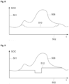
- Fig. 9 shows a second exemplary SOC curve 512 of a selected battery module.
- the battery is first discharged resulting in a lower SOC. Later it is charged for a higher SOC.
- the charge and discharge is not correlated with curve 503 and is only for recovery and/or measurements of the selected batter module.
- Fig. 10 shows a third exemplary SOC curve 514 of a selected battery module together with a curve indicating the current i 503 of the selected battery module.
- the SOC 514 of the selected battery module is approximately constant.
- the current through the selected battery module is approximately zero except for the intervals, where short positive and negative current pulses 522, 524 are fed through the selected battery module.
- Fig. 11 shows an embodiment of a multilevel converter control.
- the control may be part of a controller. It may be implemented as software on a memory device and may be executed by a microcontroller or microprocessor. It may also be part of a control device.
- a multilevel converter 806 may be connected to a power grid 820 or any other load/source herein referred to as grid.
- the control further includes a grid voltage filter 802 and a current controller 804.
- the current controller 804 receives a measured grid current 814 and/or output current of the multi-level converter. It further receives a current set point 807 from which it generates a current controller output 805.
- the grid voltage filter 802 receives a measured grid voltage 812 and/or output voltage of the multilevel converter and generates a grid voltage estimate 803 including a direct component and its quadrature component.
- the direct component is added e.g., by a summing node 808 to the current controller output 805 and fed to the multilevel converter 806.
- one or more further rested battery modules can be put in a connected state for short time intervals, generating pulses with sequential positive and negative pulse currents 623. These may result in voltage response 633, thermal response 613, and SOC response 643.
- positive and negative current pulses can be used to transfer a specific charge, the charge may be in sum also zero. This test may be repeated during different rest intervals with different SOCs of the battery.
- the pulses may be positive or negative in current while operation without negative effects to the MLC operation of the storage system.
Landscapes
- Engineering & Computer Science (AREA)
- Mechanical Engineering (AREA)
- Sustainable Development (AREA)
- Sustainable Energy (AREA)
- Power Engineering (AREA)
- Transportation (AREA)
- Life Sciences & Earth Sciences (AREA)
- Manufacturing & Machinery (AREA)
- Chemical & Material Sciences (AREA)
- Chemical Kinetics & Catalysis (AREA)
- Electrochemistry (AREA)
- General Chemical & Material Sciences (AREA)
- Charge And Discharge Circuits For Batteries Or The Like (AREA)
- Secondary Cells (AREA)
Applications Claiming Priority (1)
| Application Number | Priority Date | Filing Date | Title |
|---|---|---|---|
| EP23192664.3A EP4513707A1 (de) | 2023-08-22 | 2023-08-22 | Batteriespeichersystem und verfahren zur bereitstellung einer verbesserten batterielebensdauer |
Publications (2)
| Publication Number | Publication Date |
|---|---|
| EP4513710A2 true EP4513710A2 (de) | 2025-02-26 |
| EP4513710A3 EP4513710A3 (de) | 2025-04-30 |
Family
ID=87762869
Family Applications (2)
| Application Number | Title | Priority Date | Filing Date |
|---|---|---|---|
| EP23192664.3A Withdrawn EP4513707A1 (de) | 2023-08-22 | 2023-08-22 | Batteriespeichersystem und verfahren zur bereitstellung einer verbesserten batterielebensdauer |
| EP24187580.6A Pending EP4513710A3 (de) | 2023-08-22 | 2024-07-10 | Batteriespeichersystem und verfahren zur bereitstellung einer verbesserten batterielebensdauer |
Family Applications Before (1)
| Application Number | Title | Priority Date | Filing Date |
|---|---|---|---|
| EP23192664.3A Withdrawn EP4513707A1 (de) | 2023-08-22 | 2023-08-22 | Batteriespeichersystem und verfahren zur bereitstellung einer verbesserten batterielebensdauer |
Country Status (3)
| Country | Link |
|---|---|
| EP (2) | EP4513707A1 (de) |
| CN (1) | CN121794865A (de) |
| WO (1) | WO2025040306A1 (de) |
Families Citing this family (1)
| Publication number | Priority date | Publication date | Assignee | Title |
|---|---|---|---|---|
| DE102024120546A1 (de) * | 2024-07-19 | 2026-01-22 | Bayerische Motoren Werke Aktiengesellschaft | Verfahren zum Kalibrieren eines Batterietemperaturmodells für eine Traktionsbatterie, Traktionsbatterie für ein Kraftfahrzeug sowie Kraftfahrzeug |
Citations (2)
| Publication number | Priority date | Publication date | Assignee | Title |
|---|---|---|---|---|
| US20130234667A1 (en) | 2010-11-25 | 2013-09-12 | Cheevc Ltd | Battery management system and method |
| US20140049230A1 (en) | 2010-11-30 | 2014-02-20 | Technische Universitaet Muenchen | Novel multi-level converter topology with the possibility of dynamically connecting individual modules in series and in parallel |
Family Cites Families (3)
| Publication number | Priority date | Publication date | Assignee | Title |
|---|---|---|---|---|
| JP5673512B2 (ja) * | 2011-12-01 | 2015-02-18 | トヨタ自動車株式会社 | 蓄電システムおよび蓄電素子の温度推定方法 |
| GB2518759A (en) * | 2014-09-29 | 2015-04-01 | Daimler Ag | Battery management system for a motor vehicle |
| US11897362B2 (en) * | 2021-05-04 | 2024-02-13 | Exro Technologies Inc. | Systems and methods for individual control of a plurality of controllable units of battery cells |
-
2023
- 2023-08-22 EP EP23192664.3A patent/EP4513707A1/de not_active Withdrawn
-
2024
- 2024-07-10 CN CN202480054113.1A patent/CN121794865A/zh active Pending
- 2024-07-10 WO PCT/EP2024/069428 patent/WO2025040306A1/en active Pending
- 2024-07-10 EP EP24187580.6A patent/EP4513710A3/de active Pending
Patent Citations (2)
| Publication number | Priority date | Publication date | Assignee | Title |
|---|---|---|---|---|
| US20130234667A1 (en) | 2010-11-25 | 2013-09-12 | Cheevc Ltd | Battery management system and method |
| US20140049230A1 (en) | 2010-11-30 | 2014-02-20 | Technische Universitaet Muenchen | Novel multi-level converter topology with the possibility of dynamically connecting individual modules in series and in parallel |
Also Published As
| Publication number | Publication date |
|---|---|
| EP4513710A3 (de) | 2025-04-30 |
| CN121794865A (zh) | 2026-04-03 |
| EP4513707A1 (de) | 2025-02-26 |
| WO2025040306A1 (en) | 2025-02-27 |
Similar Documents
| Publication | Publication Date | Title |
|---|---|---|
| JP6936578B2 (ja) | バッテリパックの充電装置及び方法 | |
| CN1998110B (zh) | 平衡锂离子或锂聚合物电池的充电的方法 | |
| US20130187465A1 (en) | Power management system | |
| JPH01148030A (ja) | バッテリー充電装置 | |
| CN102405577B (zh) | 电池充电器、电气系统和可充电电池充电方法 | |
| EP2548283A2 (de) | Managementsysteme für batteriezellenumrichter | |
| JP3828354B2 (ja) | バッテリセル用セルシャント回路 | |
| US9692239B2 (en) | Method for battery equalization | |
| JP2015195674A (ja) | 蓄電池集合体制御システム | |
| JP2023526829A (ja) | バッテリー制御装置、バッテリーシステム、電源供給システム及びバッテリー制御方法 | |
| EP4513710A2 (de) | Batteriespeichersystem und verfahren zur bereitstellung einer verbesserten batterielebensdauer | |
| CN108565914B (zh) | 电池组循环充放电系统及方法 | |
| RU2479894C2 (ru) | СПОСОБ ЗАРЯДА ЛИТИЙ-ИОННОЙ АККУМУЛЯТОРНОЙ БАТАРЕИ ИЗ n ПОСЛЕДОВАТЕЛЬНО СОЕДИНЕННЫХ АККУМУЛЯТОРОВ С ПОДКЛЮЧЕННЫМИ К НИМ ЧЕРЕЗ КОММУТАТОРЫ БАЛАНСИРОВОЧНЫМИ РЕЗИСТОРАМИ | |
| JP5861063B2 (ja) | 蓄電装置及び電力供給システム | |
| US11316352B2 (en) | Battery management | |
| JP4727562B2 (ja) | 充電方法および充電回路 | |
| CN108574326B (zh) | 并联电池组的放电控制方法 | |
| KR20170087821A (ko) | 배터리 팩 충전 장치 및 방법 | |
| JP7097456B2 (ja) | 蓄電システムおよび充電制御方法 | |
| CN103516015A (zh) | 用于为电能存储器充电的方法和装置 | |
| ELVIRA et al. | Active battery balancing via a switched DC/DC converter: Description and performance analysis | |
| WO2016205079A1 (en) | Apparatus and method for charging valve regulated lead acid batteries | |
| CN116231875A (zh) | 一种储能系统及其控制方法 | |
| La et al. | Reactive balancing circuit for paralleled battery modules employing dynamic capacitance modulation | |
| KR102409123B1 (ko) | 다수의 전력 저장 장치를 이용한 전력 관리 시스템 |
Legal Events
| Date | Code | Title | Description |
|---|---|---|---|
| PUAI | Public reference made under article 153(3) epc to a published international application that has entered the european phase |
Free format text: ORIGINAL CODE: 0009012 |
|
| STAA | Information on the status of an ep patent application or granted ep patent |
Free format text: STATUS: THE APPLICATION HAS BEEN PUBLISHED |
|
| AK | Designated contracting states |
Kind code of ref document: A2 Designated state(s): AL AT BE BG CH CY CZ DE DK EE ES FI FR GB GR HR HU IE IS IT LI LT LU LV MC ME MK MT NL NO PL PT RO RS SE SI SK SM TR |
|
| PUAL | Search report despatched |
Free format text: ORIGINAL CODE: 0009013 |
|
| AK | Designated contracting states |
Kind code of ref document: A3 Designated state(s): AL AT BE BG CH CY CZ DE DK EE ES FI FR GB GR HR HU IE IS IT LI LT LU LV MC ME MK MT NL NO PL PT RO RS SE SI SK SM TR |
|
| RIC1 | Information provided on ipc code assigned before grant |
Ipc: H01M 10/48 20060101ALI20250325BHEP Ipc: H01M 10/44 20060101ALI20250325BHEP Ipc: G01R 31/392 20190101ALI20250325BHEP Ipc: B60L 58/21 20190101ALI20250325BHEP Ipc: B60L 58/19 20190101ALI20250325BHEP Ipc: H02J 7/00 20060101AFI20250325BHEP |
|
| STAA | Information on the status of an ep patent application or granted ep patent |
Free format text: STATUS: REQUEST FOR EXAMINATION WAS MADE |
|
| 17P | Request for examination filed |
Effective date: 20250818 |