EP4513741A1 - Convertisseur multimoteur pour plusieurs moteurs et procédé de détection des déplacements des vitesses du moteur - Google Patents
Convertisseur multimoteur pour plusieurs moteurs et procédé de détection des déplacements des vitesses du moteur Download PDFInfo
- Publication number
- EP4513741A1 EP4513741A1 EP24194625.0A EP24194625A EP4513741A1 EP 4513741 A1 EP4513741 A1 EP 4513741A1 EP 24194625 A EP24194625 A EP 24194625A EP 4513741 A1 EP4513741 A1 EP 4513741A1
- Authority
- EP
- European Patent Office
- Prior art keywords
- current
- motor
- motors
- target
- soll
- Prior art date
- Legal status (The legal status is an assumption and is not a legal conclusion. Google has not performed a legal analysis and makes no representation as to the accuracy of the status listed.)
- Pending
Links
Images

Classifications
-
- H—ELECTRICITY
- H02—GENERATION; CONVERSION OR DISTRIBUTION OF ELECTRIC POWER
- H02P—CONTROL OR REGULATION OF ELECTRIC MOTORS, ELECTRIC GENERATORS OR DYNAMO-ELECTRIC CONVERTERS; CONTROLLING TRANSFORMERS, REACTORS OR CHOKE COILS
- H02P21/00—Arrangements or methods for the control of electric machines by vector control, e.g. by control of field orientation
- H02P21/22—Current control, e.g. using a current control loop
-
- H—ELECTRICITY
- H02—GENERATION; CONVERSION OR DISTRIBUTION OF ELECTRIC POWER
- H02P—CONTROL OR REGULATION OF ELECTRIC MOTORS, ELECTRIC GENERATORS OR DYNAMO-ELECTRIC CONVERTERS; CONTROLLING TRANSFORMERS, REACTORS OR CHOKE COILS
- H02P6/00—Arrangements for controlling synchronous motors or other dynamo-electric motors using electronic commutation dependent on the rotor position; Electronic commutators therefor
- H02P6/04—Arrangements for controlling or regulating the speed or torque of more than one motor
-
- H—ELECTRICITY
- H02—GENERATION; CONVERSION OR DISTRIBUTION OF ELECTRIC POWER
- H02P—CONTROL OR REGULATION OF ELECTRIC MOTORS, ELECTRIC GENERATORS OR DYNAMO-ELECTRIC CONVERTERS; CONTROLLING TRANSFORMERS, REACTORS OR CHOKE COILS
- H02P21/00—Arrangements or methods for the control of electric machines by vector control, e.g. by control of field orientation
- H02P21/05—Arrangements or methods for the control of electric machines by vector control, e.g. by control of field orientation specially adapted for damping motor oscillations, e.g. for reducing hunting
-
- H—ELECTRICITY
- H02—GENERATION; CONVERSION OR DISTRIBUTION OF ELECTRIC POWER
- H02P—CONTROL OR REGULATION OF ELECTRIC MOTORS, ELECTRIC GENERATORS OR DYNAMO-ELECTRIC CONVERTERS; CONTROLLING TRANSFORMERS, REACTORS OR CHOKE COILS
- H02P5/00—Arrangements specially adapted for regulating or controlling the speed or torque of two or more electric motors
-
- H—ELECTRICITY
- H02—GENERATION; CONVERSION OR DISTRIBUTION OF ELECTRIC POWER
- H02P—CONTROL OR REGULATION OF ELECTRIC MOTORS, ELECTRIC GENERATORS OR DYNAMO-ELECTRIC CONVERTERS; CONTROLLING TRANSFORMERS, REACTORS OR CHOKE COILS
- H02P6/00—Arrangements for controlling synchronous motors or other dynamo-electric motors using electronic commutation dependent on the rotor position; Electronic commutators therefor
- H02P6/24—Arrangements for stopping
-
- H—ELECTRICITY
- H02—GENERATION; CONVERSION OR DISTRIBUTION OF ELECTRIC POWER
- H02P—CONTROL OR REGULATION OF ELECTRIC MOTORS, ELECTRIC GENERATORS OR DYNAMO-ELECTRIC CONVERTERS; CONTROLLING TRANSFORMERS, REACTORS OR CHOKE COILS
- H02P6/00—Arrangements for controlling synchronous motors or other dynamo-electric motors using electronic commutation dependent on the rotor position; Electronic commutators therefor
- H02P6/04—Arrangements for controlling or regulating the speed or torque of more than one motor
- H02P2006/045—Control of current
Definitions
- the invention relates to a method and a sensorless multi-motor converter for parallel operation of at least two, in particular several motors, as well as a control method for operating the two or more motors on a common multi-motor converter, in particular with the ability to detect and control the rotor positions or shifts in the speeds of the motors.
- the motor drive device comprises an inverter which comprises a number of matching switching elements and supplies alternating current to a first motor and a second motor by converting direct current into alternating current by switching the switching elements, and a control unit which controls the inverter.
- the control unit sets a target value for the magnetic flux current according to a speed difference or a phase difference of the first motor and the second motor, and controls the inverter based on a switching control signal based on the set target value for the magnetic flux current. Accordingly, a speed error can be reduced when controlling a plurality of motors connected in parallel at the same time.
- KOS reference coordinate system
- This can be one of the two motor KOS or the inverter KOS, which is based on the total currents of the motors.
- an additional, namely another (third) observer is required. If the system is now fully determined by the observers, a control system can be set up including a stabilization controller, which switches on a d-current component based on the speed and angle information of the individual motors.
- the invention is based on the following starting point.
- An inverter has a current detection circuit at the output, with which the current flowing from the inverter into a system of several motors can be detected.
- the rotor position of the entire system is then detected for the system of several motors (preferably PMSM). This is not necessarily identical to the individual rotor positions. of the motors in the overall system. Furthermore, no statement can be made about the position of an individual motor.
- a well-known field-oriented FOC control method can be used to regulate the speed or torque of such an overall system.
- the high complexity of the FOC requires a programmable component that can efficiently handle the vector mathematics of the Clarke and Park transformations on which the FOC is based.
- the disadvantage here is the required current measurement of all motor phases and the corresponding number of observers required. By using the inverter output current, these can in principle be reduced. However, this leads to oscillations between the motors, which cannot be detected by the inverter and the overall system, which is also considered a disadvantage. Furthermore, it must be ensured that each motor operates at a safe operating point.
- a key difference of the multi-motor converter according to the invention is that a detection device or detection method is added, which offers the possibility of detecting the rotor position of individual motors within the overall system and adjusting it accordingly.
- PMSM / EC motor rotor position sensor
- a basic idea of the invention is to measure the phase current for the corresponding motor using (at least) one additional current detection device or circuit, thereby eliminating the need for observers that would otherwise be required.
- oscillations and the state of a system consisting of several motors can be detected and then regulated accordingly by a stabilization controller.
- DE 10 2018 124 209 A1 A control system comprising a multi-motor converter (PWR) for the controlled parallel operation of a number of n EC motors (M1, ..., Mn) is already known, the respective rotor position of which is detected without sensors.
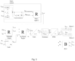
- PWR multi-motor converter
- the following two concepts are provided as preferred solutions for detecting the rotor position shift. Either the detection of the system oscillation (oscillation of the motors) based on the phase current information by means of d-q transformation and alternatively based on the direct rotor position-dependent current sampling.
- a detection device RLU for determining at least the rotor position and speed of a fictitious motor at the converter output using the previously measured phase currents or the total current I u,v,w and the terminal voltage U u,v,w of the two EC motors.
- the detection device RLU is thus particularly designed to determine the rotor position ⁇ U to obtain , where the total current I uvw is used as input variable and the terminal voltage U uvw is also used to determine the variables rotor position ⁇ U and speed ⁇ U.
Landscapes
- Engineering & Computer Science (AREA)
- Power Engineering (AREA)
- Control Of Multiple Motors (AREA)
Applications Claiming Priority (1)
| Application Number | Priority Date | Filing Date | Title |
|---|---|---|---|
| DE102023122262.7A DE102023122262A1 (de) | 2023-08-21 | 2023-08-21 | Mehrmotorenumrichter für mehrere Motoren und Detektionsverfahren zum Detektieren der Verschiebungen der Drehzahlen der Motoren |
Publications (1)
| Publication Number | Publication Date |
|---|---|
| EP4513741A1 true EP4513741A1 (fr) | 2025-02-26 |
Family
ID=92424423
Family Applications (1)
| Application Number | Title | Priority Date | Filing Date |
|---|---|---|---|
| EP24194625.0A Pending EP4513741A1 (fr) | 2023-08-21 | 2024-08-14 | Convertisseur multimoteur pour plusieurs moteurs et procédé de détection des déplacements des vitesses du moteur |
Country Status (3)
| Country | Link |
|---|---|
| US (1) | US20250070692A1 (fr) |
| EP (1) | EP4513741A1 (fr) |
| DE (1) | DE102023122262A1 (fr) |
Citations (3)
| Publication number | Priority date | Publication date | Assignee | Title |
|---|---|---|---|---|
| KR101687556B1 (ko) | 2015-08-31 | 2016-12-19 | 엘지전자 주식회사 | 모터 구동장치 및 이를 구비하는 홈 어플라이언스 |
| DE102018124209A1 (de) | 2018-10-01 | 2020-04-02 | Ebm-Papst Mulfingen Gmbh & Co. Kg | Mehrmotorenumrichter |
| EP3998702A1 (fr) * | 2019-07-09 | 2022-05-18 | Mitsubishi Electric Corporation | Dispositif d'entraînement, dispositif d'utilisation de fluide et climatiseur |
Family Cites Families (1)
| Publication number | Priority date | Publication date | Assignee | Title |
|---|---|---|---|---|
| US11424698B2 (en) * | 2019-01-16 | 2022-08-23 | Mitsubishi Electric Corporation | Motor control device and air-conditioning device |
-
2023
- 2023-08-21 DE DE102023122262.7A patent/DE102023122262A1/de active Pending
-
2024
- 2024-08-14 EP EP24194625.0A patent/EP4513741A1/fr active Pending
- 2024-08-20 US US18/809,728 patent/US20250070692A1/en active Pending
Patent Citations (3)
| Publication number | Priority date | Publication date | Assignee | Title |
|---|---|---|---|---|
| KR101687556B1 (ko) | 2015-08-31 | 2016-12-19 | 엘지전자 주식회사 | 모터 구동장치 및 이를 구비하는 홈 어플라이언스 |
| DE102018124209A1 (de) | 2018-10-01 | 2020-04-02 | Ebm-Papst Mulfingen Gmbh & Co. Kg | Mehrmotorenumrichter |
| EP3998702A1 (fr) * | 2019-07-09 | 2022-05-18 | Mitsubishi Electric Corporation | Dispositif d'entraînement, dispositif d'utilisation de fluide et climatiseur |
Non-Patent Citations (2)
| Title |
|---|
| LEE YONGJAE ET AL: "Control Method of Monoinverter Dual Parallel Drive System With Interior Permanent Magnet Synchronous Machines", IEEE TRANSACTIONS ON POWER ELECTRONICS, INSTITUTE OF ELECTRICAL AND ELECTRONICS ENGINEERS, USA, vol. 31, no. 10, 1 October 2016 (2016-10-01), pages 7077 - 7086, XP011610968, ISSN: 0885-8993, [retrieved on 20160520], DOI: 10.1109/TPEL.2015.2508063 * |
| PARK CHEONSU ET AL: "Control Method of Dual Parallel Surface-Mounted Permanent-Magnet Synchronous Motor Systems with Different Parameters Using Single Inverter", 2022 IEEE ENERGY CONVERSION CONGRESS AND EXPOSITION (ECCE), IEEE, 9 October 2022 (2022-10-09), pages 1 - 8, XP034239274, DOI: 10.1109/ECCE50734.2022.9947789 * |
Also Published As
| Publication number | Publication date |
|---|---|
| DE102023122262A1 (de) | 2025-02-27 |
| US20250070692A1 (en) | 2025-02-27 |
Similar Documents
| Publication | Publication Date | Title |
|---|---|---|
| EP2421148B1 (fr) | Dispositif et procédé d'identification des paramètres de référence mécaniques d'un moteur asynchrone triphasé sans utilisation d'encodeur de vitesse | |
| EP2227857B1 (fr) | Commutation d'un appareil de commande sur une machine asynchrone fonctionnant sans capteur de rotation | |
| EP0884835B1 (fr) | Méthode et dispositif pour contrôler par orientation de son champ un moteur asynchrone sans capteur | |
| EP0847617B1 (fr) | Procede et dispositif de correction de la direction de flux d'un modele de flux d'un moteur a champ rotatif, commande sans capteur et par orientation de champ jusqu'a une frequence zero | |
| EP2421145B1 (fr) | Dispositif et procédé d'identification des paramètres d'un schéma électrique équivalent d'un moteur asynchrone triphasé sans utilisation d'encodeur de vitesse | |
| DE69505577T2 (de) | Apparat zur Steuerung eines Induktionsmotor mit veränderlicher Geschwindigkeit | |
| EP2226929B1 (fr) | Système de surveillance de la plausibilité pour des mesures de mouvements sur un dispositif d'entraînement électrique | |
| EP3861629B1 (fr) | Convertisseur multi-moteur et procédé | |
| DE102006006032A1 (de) | Verfahren und Vorrichtung zum Betreiben einer Synchronmaschine | |
| DE102020109004A1 (de) | Verfahren zum Erfassen einer Rotorlage einer permanenterregten Synchronmaschine und permanenterregte Synchronmaschine mit Mitteln zum Erfassen ihrer Rotorlage | |
| EP1121740A1 (fr) | Dispositif pour surveiller le systeme de mesure d'une commande electrique | |
| DE10311028A1 (de) | Verfahren zur Bestimmung einer Startrotorlage und Drehzahl bei Impulsfreigabe einer stromrichtergespeisten, permanenterregten Synchronmaschine ohne Lage-und Drehzahlgeber | |
| EP4342069B1 (fr) | Procédé et dispositif pour déterminer une différence d'angle | |
| EP3729634B1 (fr) | Procédé de détermination de la position d'un rotor d'une machine triphaseé, sans l'utilisation d'un encodeur, et dispositif de régulation d'un moteur triphasé sans l'utilisation d'un encodeur | |
| DE102023122262A1 (de) | Mehrmotorenumrichter für mehrere Motoren und Detektionsverfahren zum Detektieren der Verschiebungen der Drehzahlen der Motoren | |
| EP1334546B1 (fr) | Dispositif et procede permettant de determiner l'angle du rotor electrique au demarrage | |
| DE19928481A1 (de) | Verfahren zur vereinfachten feldorientierten Regelung von Asynchronmaschinen | |
| EP3704790B1 (fr) | Procédé de détermination de la position du rotor de machines électriques synchrones sans capteur mécanique | |
| DE102021213595A1 (de) | Verfahren zum Ermitteln einer Korrekturinformation, Verfahren zur Regelung einer elektrischen Maschine, Vorrichtung, elektrische Antriebseinrichtung, Wärmepumpe | |
| DE69824420T2 (de) | Steuer- und Überwachungseinrichtung für die Öffnung oder die Schliessung eines elektrischen Betätigungselementes | |
| DE102020201087A1 (de) | Verfahren und Vorrichtung zum Betreiben einer Elektromaschine, Antriebseinrichtung | |
| DE102020134926A1 (de) | Steuervorrichtung und verfahren zur steuerung einer elektrischen servolenkung | |
| DE102023119025B4 (de) | Steuereinheit und Verfahren zum Steuern eines Betriebs einer Drehstrom-Maschine, Computerprogrammprodukt und Antriebsstrang | |
| EP4224704B1 (fr) | Machine électrique commutée électroniquement comprenant plusieurs machines partielles et procédé de fonctionnement d'une telle machine électrique | |
| EP4557602A1 (fr) | Convertisseur multimoteur |
Legal Events
| Date | Code | Title | Description |
|---|---|---|---|
| PUAI | Public reference made under article 153(3) epc to a published international application that has entered the european phase |
Free format text: ORIGINAL CODE: 0009012 |
|
| STAA | Information on the status of an ep patent application or granted ep patent |
Free format text: STATUS: THE APPLICATION HAS BEEN PUBLISHED |
|
| AK | Designated contracting states |
Kind code of ref document: A1 Designated state(s): AL AT BE BG CH CY CZ DE DK EE ES FI FR GB GR HR HU IE IS IT LI LT LU LV MC ME MK MT NL NO PL PT RO RS SE SI SK SM TR |
|
| STAA | Information on the status of an ep patent application or granted ep patent |
Free format text: STATUS: REQUEST FOR EXAMINATION WAS MADE |
|
| 17P | Request for examination filed |
Effective date: 20250731 |