EP4514029A1 - Terminal, station de base, procédé de communication, et circuit intégré - Google Patents
Terminal, station de base, procédé de communication, et circuit intégré Download PDFInfo
- Publication number
- EP4514029A1 EP4514029A1 EP23791591.3A EP23791591A EP4514029A1 EP 4514029 A1 EP4514029 A1 EP 4514029A1 EP 23791591 A EP23791591 A EP 23791591A EP 4514029 A1 EP4514029 A1 EP 4514029A1
- Authority
- EP
- European Patent Office
- Prior art keywords
- scheduling
- pusch
- data signal
- slot
- timing
- Prior art date
- Legal status (The legal status is an assumption and is not a legal conclusion. Google has not performed a legal analysis and makes no representation as to the accuracy of the status listed.)
- Pending
Links
Images


Classifications
-
- H—ELECTRICITY
- H04—ELECTRIC COMMUNICATION TECHNIQUE
- H04W—WIRELESS COMMUNICATION NETWORKS
- H04W72/00—Local resource management
- H04W72/12—Wireless traffic scheduling
- H04W72/1263—Mapping of traffic onto schedule, e.g. scheduled allocation or multiplexing of flows
- H04W72/1268—Mapping of traffic onto schedule, e.g. scheduled allocation or multiplexing of flows of uplink data flows
-
- H—ELECTRICITY
- H04—ELECTRIC COMMUNICATION TECHNIQUE
- H04W—WIRELESS COMMUNICATION NETWORKS
- H04W72/00—Local resource management
- H04W72/04—Wireless resource allocation
- H04W72/044—Wireless resource allocation based on the type of the allocated resource
- H04W72/0446—Resources in time domain, e.g. slots or frames
-
- H—ELECTRICITY
- H04—ELECTRIC COMMUNICATION TECHNIQUE
- H04L—TRANSMISSION OF DIGITAL INFORMATION, e.g. TELEGRAPHIC COMMUNICATION
- H04L1/00—Arrangements for detecting or preventing errors in the information received
- H04L1/08—Arrangements for detecting or preventing errors in the information received by repeating transmission, e.g. Verdan system
-
- H—ELECTRICITY
- H04—ELECTRIC COMMUNICATION TECHNIQUE
- H04L—TRANSMISSION OF DIGITAL INFORMATION, e.g. TELEGRAPHIC COMMUNICATION
- H04L1/00—Arrangements for detecting or preventing errors in the information received
- H04L1/12—Arrangements for detecting or preventing errors in the information received by using return channel
- H04L1/16—Arrangements for detecting or preventing errors in the information received by using return channel in which the return channel carries supervisory signals, e.g. repetition request signals
- H04L1/18—Automatic repetition systems, e.g. Van Duuren systems
- H04L1/1867—Arrangements specially adapted for the transmitter end
- H04L1/1887—Scheduling and prioritising arrangements
-
- H—ELECTRICITY
- H04—ELECTRIC COMMUNICATION TECHNIQUE
- H04L—TRANSMISSION OF DIGITAL INFORMATION, e.g. TELEGRAPHIC COMMUNICATION
- H04L1/00—Arrangements for detecting or preventing errors in the information received
- H04L1/12—Arrangements for detecting or preventing errors in the information received by using return channel
- H04L1/16—Arrangements for detecting or preventing errors in the information received by using return channel in which the return channel carries supervisory signals, e.g. repetition request signals
- H04L1/18—Automatic repetition systems, e.g. Van Duuren systems
- H04L1/1867—Arrangements specially adapted for the transmitter end
- H04L1/189—Transmission or retransmission of more than one copy of a message
Definitions
- the present disclosure relates to a terminal, a base station, a communication method, and an integrated circuit.
- the usage of mobile communication is expanding to all fields such as automobiles, houses, home electric appliances, or industrial equipment in addition to information terminals such as smartphones.
- IoT Internet of Things
- a substantial improvement in the performance and function of mobile communication systems has been required for various requirements such as an increase in the number of connected devices or low latency in addition to an increase in system capacity.
- the 5th generation mobile communication systems has features such as enhanced mobile broadband (eMBB), massive machine type communication (mMTC), and ultra reliable and low latency communication (URLLC), and can flexibly provide radio communication in response to a wide variety of needs.
- eMBB enhanced mobile broadband
- mMTC massive machine type communication
- URLLC ultra reliable and low latency communication
- the 3rd Generation Partnership Project (3GPP) as an international standardizing body has been specifying New Radio (NR) as one of 5G radio interfaces.
- NR New Radio
- NPL Non-Patent Literature
- a non-limiting embodiment of the present disclosure facilitates providing a terminal, a base station, a communication method, and an integrated circuit each capable of improving the reception performance of a signal in the uplink.
- a terminal includes: reception circuitry, which, in operation, receives first control information scheduling a first data signal and receives second control information scheduling a second data signal later than the first control information for the first data signal and the second data signal, at least one of the first data signal and the second data signal being transmitted repeatedly; and control circuitry, which, in operation, determines whether the scheduling is defined scheduling, based on a first timing for a transmission of the first data signal and a second timing for a transmission of the second data signal.
- a signal can be appropriately transmitted in the uplink.
- FR1 Frequency Range 1
- FR2 Frequency Range 2
- FR1 a millimeter-wave band such as 28 GHz or 39 GHz band capable of ensuring a wide band
- FR2 Frequency Range 2
- FR1 a high frequency band is possibly used compared with the frequency band used in Long Term Evolution (LTE) or 3rd Generation mobile communication systems (3G) such as 3.5 GHz band.
- LTE Long Term Evolution
- 3G 3rd Generation mobile communication systems
- NR for example, it is expected to ensure almost the same communication area (or coverage) as in the Radio Access Technology (RAT) such LTE or 3G, in other words, to ensure an appropriate communication quality when the high frequency band is used compared with LTE or 3G.
- RAT Radio Access Technology
- 3GPP Release 17 e.g., referred to as "Rel. 17”
- a method of improving the coverage in NR has been studied (e.g., see NPL 2).
- a terminal transmits/receives data in accordance with, for example, resource allocation indicated by a layer 1 control signal (for example, Downlink Control Information (DCI)) on a downlink control channel (for example, Physical Downlink Control Channel (PDCCH)) from a base station (for example, also referred to as gNB) or Radio Resource Control (RRC) that is layer 3 (for example, see NPLs 3 to 6).
- a layer 1 control signal for example, Downlink Control Information (DCI)
- DCI Downlink Control Information
- PDCCH Physical Downlink Control Channel
- RRC Radio Resource Control
- a terminal transmits an uplink data channel (for example, Physical Uplink Shared Channel (PUSCH)) in accordance with a resource allocation from a base station (for example, Grant or UL grant).
- the resource allocation information included in at least one of the DCI and RRC may include, for example, information on a time domain resource on which PUSCH is transmitted.
- the information on the time domain resource may include information on the timing until the terminal transmits the PUSCH from the slot in which the PDCCH is received (for example, K2), the leading symbol position of the PUSCH in the slot, or information on the number of symbols for the PUSCH transmission.
- NR Release 15 or NR Release 16 referred to as "NR Rel. 15/16", for example
- HARQ process ID#A the scheduling of any two Hybrid Automatic Repeat reQuest (HARQ) process ID#A and HARQ process ID#B is defined.
- a DCI also referred to as PDCCH#A, for example
- a DCI also referred to as PDCCH#B, for example
- the terminal does not assume that PUSCH#B is scheduled to be transmitted earlier than PUSCH#A.
- PUSCH#B being scheduled to be transmitted earlier than PUSCH#A to the terminal is referred to as "Out-of-order scheduling.”
- FIG. 1 illustrates an example of Out-of-order scheduling and an example of normal scheduling (referred to as "In-order scheduling", for example).
- a terminal (UE) not assuming Out-of-order scheduling is defined as follows (see, for example, NPL 6).
- the terminal Since the terminal does not assume Out-of-order scheduling, the terminal operation in a case of Out-of-order scheduling is not defined in the standard. For this reason, the base station is expected to schedule PUSCH so as to avoid Out-of-order scheduling, for example.
- a method for transmitting PUSCH using a plurality of slots (also referred to as Repetition or repetition transmission) is supported.
- information on the time domain resource for PUSCH transmission may include information on the number of Repetitions.
- PUSCH Repetition For example, in NR Rel. 15/16, two PUSCH repetition methods are defined for PUSCH Repetition (see, for example, NPL 6).
- the first PUSCH repetition method is Repetition in a slot unit, and the same time resource allocation is applied to a plurality of continuous slots.
- this PUSCH repetition method will be referred to as "PUSCH repetition Type A with continuous slot counting.”
- the second PUSCH repetition method is Repetition by which one or a plurality of PUSCHs repetition transmission is possible within one slot.
- this PUSCH repetition method will be referred to as "PUSCH repetition Type B".
- the base station may indicate, to the terminal, for example, a time domain resource and the number of repetitions for the first (initial) PUSCH transmission.
- time domain resource allocation for the second and each subsequent PUSCH transmission for example, time domain resources corresponding to symbols that are continuous with and have the same number of symbols as symbols for the previous PUSCH transmission may be allocated to the PUSCH.
- the number of repetition slots may be, for example, a value counted based on continuous slots.
- NR Release 17 for example, referred to as "NR Rel. 17”
- a method has been introduced in which the number of the repetition slots is set to a value counted based on an uplink slot (available slot) that can be used for PUSCH transmission, as a functional expansion of PUSCH repetition Type A (see, for example, NPLs 2 and 6).
- this PUSCH repetition method will be referred to as "PUSCH repetition Type A with available slot counting.”
- the number of repetition slots is counted based on an uplink slot that is available for PUSCH transmission.
- the method for determining the uplink slot available for PUSCH transmission may depend on, for example, a slot format (Slot Format Indication (SFI)) indication configured in advance by RRC (for example, semi-static SFI), and information on the time resource allocation for PUSCH transmission.
- SFI Slot Format Indication
- the terminal may determine whether to actually transmit PUSCH in each uplink slot that is available for PUSCH transmission, based on a dynamic indication (for example, an indication by DCI), for example.
- a dynamic indication for example, an indication by DCI
- the dynamic indication may be a dynamic SFI indication (dynamic SFI), an uplink transmission cancellation indication (UpLink Cancellation Indication (UL CI)), an uplink transmission allocation with a high priority, and the like.
- the slot may be counted as the number of repetition slots.
- a dynamic indication for example, indication by DCI.
- the criterion for determining whether PUSCH transmission is "In-order scheduling” or “Out-of-order scheduling” is "whether PUSCH transmission#B is scheduled to be transmitted earlier than the end (the end of the first PUSCH) of PUSCH transmission#A when scheduling DCI of PUSCH transmission#A (HARQ process ID#A, or first PUSCH) is received temporally earlier than scheduling DCI of PUSCH transmission#B (HARQ process ID#B)."
- the scheduling is determined to be "Out-of-order scheduling.”
- the scheduling is determined to be "In-order scheduling.”
- the slot (or symbol) in which PUSCH transmission is started and the last slot (or symbol) of the PUSCH transmission are determined based on the uplink slot available for PUSCH transmission. Further, there is a case where PUSCH is not transmitted in a certain slot (for example, in a case where PUSCH transmission is dropped) by the dynamic indication in the uplink slot that is available for PUSCH transmission.
- the slot in which the PUSCH transmission is actually started may be the uplink slot available for PUSCH transmission following the first slot.
- the slot in which the PUSCH transmission is actually ended may be a slot before the last slot.
- a method for appropriately determining whether the scheduling is Out-of-order scheduling when PUSCH repetition Type A with available slot counting is applied to PUSCH transmission.
- the timing of the end of PUSCH transmission#A (first PUSCH) (the end of the first PUSCH) and the timing at which PUSCH transmission#B is scheduled, which are for determining whether the scheduling is Out-of-order scheduling are clearly defined in a case where PUSCH repetition Type A with available slot counting is applied to PUSCH transmission.
- the terminal can determine whether the allocation of the PUSCH transmission is Out-of-order scheduling.
- a communication system includes, for example, at least one base station and at least one terminal.
- FIG. 3 is a block diagram illustrating an exemplary configuration of a part of base station 100 according to an embodiment of the present disclosure
- FIG. 4 is a block diagram illustrating an exemplary configuration of a part of terminal 200 according to an embodiment of the present disclosure.
- a transmitter transmits first control information (for example, PDCCH#A) scheduling a first data signal (for example, PUSCH#A) and transmits second control information (for example, PDCCH#B) scheduling a second data signal (for example, PUSCH#B) later than the first control information for the first data signal and the second data signal at least one of which is transmitted repeatedly.
- first control information for example, PDCCH#A
- second control information for example, PDCCH#B
- a controller determines whether the scheduling is defined (or normal) scheduling (for example, In-order scheduling), based on a first timing for a reception of the first data signal (for example, the timing of end of PUSCH reception#A) and a second timing for a reception of the second data signal (for example, the timing at which PUSCH reception#B is scheduled).
- a receiver receives first control information (for example, PDCCH#A) scheduling a first data signal (for example, PUSCH#A) and receives second control information (for example, PDCCH#B) scheduling a second data signal (for example, PUSCH#B) later than the first control information for the first data signal and the second data signal at least one of which is transmitted repeatedly.
- first control information for example, PDCCH#A
- second control information for example, PDCCH#B
- a controller determines whether the scheduling is defined (or normal) scheduling (for example, In-order scheduling), based on a first timing for a transmission of the first data signal (for example, the timing of end of PUSCH transmission#A) and a second timing for a transmission of the second data signal (for example, the timing at which PUSCH transmission#B is scheduled).
- FIG. 5 is a block diagram illustrating an exemplary configuration of base station 100 according to Embodiment 1.
- base station 100 includes controller 101, higher-layer control signal generator 102, downlink control information generator 103, encoder 104, modulator 105, signal assigner 106, transmitter 107, receiver 108, extractor 109, demodulator 110, and decoder 111.
- controller 101 higher-layer control signal generator 102, downlink control information generator 103, encoder 104, modulator 105, signal assigner 106, extractor 109, demodulator 110, and decoder 111 illustrated in FIG. 5 may be included in the controller illustrated in FIG. 3 .
- transmitter 107 illustrated in FIG. 5 may be included in the transmitter illustrated in FIG. 3 .
- Controller 101 determines information on PUSCH transmission, and outputs the determined information to at least one of higher-layer control signal generator 102 and downlink control information generator 103, for example.
- the information on the PUSCH transmission may include, for example, time domain resource allocation information (for example, Time Domain Resource Allocation (TDRA)). Further, controller 101 outputs the determined information to extractor 109, demodulator 110, and decoder 111.
- TDRA Time Domain Resource Allocation
- controller 101 may perform the scheduling to satisfy normal scheduling (for example, In-order scheduling) (for example, satisfy that the scheduling is not out-of-order scheduling) by the method described later.
- normal scheduling for example, In-order scheduling
- controller 101 determines, for example, information on a downlink signal for transmitting a higher-layer control signal or downlink control information (e.g., Modulation and Coding Scheme (MCS) and radio resource allocation), and outputs the determined information to encoder 104, modulator 105, and signal assigner 106. Further, controller 101 outputs the information on a downlink signal (for example, higher-layer control signal) to downlink control information generator 103, for example.
- MCS Modulation and Coding Scheme
- Higher-layer control signal generator 102 generates a higher-layer control signal bit string, for example, based on the information inputted from controller 101, and outputs the higher-layer control signal bit string to encoder 104.
- Downlink control information generator 103 generates a downlink control information (for example, DCI) bit string, for example, based on the information inputted from controller 101, and outputs the generated DCI bit string to encoder 104. Note that, the control information may be transmitted to a plurality of terminals.
- DCI downlink control information
- Encoder 104 encodes the bit string inputted from higher-layer control signal generator 102 or the DCI bit string inputted from downlink control information generator 103, for example, based on the information inputted from controller 101. Encoder 104 outputs the encoded bit string to modulator 105.
- Modulator 105 modulates encoded bit string inputted from encoder 104, for example, based on the information inputted from controller 101, and outputs the modulated signal (for example, a symbol string) to signal assigner 106.
- Signal assigner 106 maps, for example, based on the information inputted from controller 101 and indicating the radio resource, the symbol string (including, for example, a control signal) inputted from modulator 105 to the radio resource. Signal assigner 106 outputs a signal that has been mapped to a downlink to transmitter 107.
- Transmitter 107 performs, for example, transmission waveform generation processing such as orthogonal frequency division multiplexing (OFDM), on a signal inputted, for example, from signal assigner 106. Further, for example, in the case of an OFDM transmission in which a cyclic prefix (CP) is added, transmitter 107 performs Inverse Fast Fourier Transform (IFFT) processing on the signal, and adds a CP to the signal after the IFFT. Further, transmitter 107 performs, for example, RF processing such as D/A conversion or up-conversion on the signal, and transmits a radio signal to terminal 200 via an antenna.
- OFDM orthogonal frequency division multiplexing
- IFFT Inverse Fast Fourier Transform
- transmitter 107 performs, for example, RF processing such as D/A conversion or up-conversion on the signal, and transmits a radio signal to terminal 200 via an antenna.
- Receiver 108 performs RF processing such as down-conversion or A/D conversion on the uplink signal received from terminal 200 through, for example, an antenna. Further, in the case of an OFDM transmission, receiver 108 performs Fast Fourier Transform (FFT) processing on the received signal, for example, and outputs the obtained frequency domain signal to extractor 109.
- FFT Fast Fourier Transform
- Extractor 109 extracts, for example, based on the information inputted from controller 101, a radio resource portion on which the uplink data signal (for example, PUSCH) is transmitted, from the received signal inputted from receiver 108, and outputs the extracted radio resource portion to demodulator 110.
- a radio resource portion on which the uplink data signal for example, PUSCH
- Demodulator 110 demodulates the uplink data signal (for example, PUSCH) inputted from extractor 109 based on the information inputted from controller 101, for example. Demodulator 110 outputs, for example, the demodulation result to decoder 111.
- uplink data signal for example, PUSCH
- Demodulator 110 outputs, for example, the demodulation result to decoder 111.
- Decoder 111 performs error correction decoding on the uplink data signal (for example, PUSCH) and obtains a decoded reception bit sequence based on the information inputted from controller 101 and the demodulation result inputted from demodulator 110, for example.
- FIG. 6 is a block diagram illustrating an exemplary configuration of terminal 200 according to an exemplary embodiment of the present disclosure.
- terminal 200 includes receiver 201, extractor 202, demodulator 203, decoder 204, controller 205, encoder 206, modulator 207, signal assigner 208, and transmitter 209.
- extractor 202 demodulator 203, decoder 204, controller 205, encoder 206, modulator 207, and signal assigner 208 illustrated in FIG. 6 may be included in the controller illustrated in FIG. 4 .
- receiver 201 illustrated in FIG. 6 may be included in the receiver illustrated in FIG. 4 .
- Receiver 201 receives a downlink signal (for example, downlink control information) from base station 100 via an antenna, performs RF processing such as down-conversion or A/D conversion on the received radio signal, and obtains a received signal (baseband signal). Further, when receiver 201 receives an OFDM signal, receiver 201 performs FFT processing on the received signal and converts the received signal into that in the frequency domain. Receiver 201 outputs the received signal to extractor 202.
- a downlink signal for example, downlink control information
- RF processing such as down-conversion or A/D conversion
- baseband signal baseband signal
- receiver 201 performs FFT processing on the received signal and converts the received signal into that in the frequency domain.
- Receiver 201 outputs the received signal to extractor 202.
- Extractor 202 extracts, for example, based on information on a radio resource in downlink control information, which is inputted from controller 205, a radio resource portion, which may include downlink control information, from the received signal inputted from receiver 201, and outputs the radio resource portion to demodulator 203. Further, extractor 202 extracts, based on information on a radio resource in a data signal, which is inputted from controller 205, a radio resource portion including downlink data, and outputs the radio resource portion to demodulator 203.
- Demodulator 203 demodulates, for example, based on information inputted from controller 205, a signal inputted (for example, PDCCH or PDSCH) from extractor 202, and outputs the demodulation result to decoder 204.
- a signal inputted for example, PDCCH or PDSCH
- Decoder 204 performs error correction decoding of PDCCH or PDSCH, for example, and obtains a higher-layer control signal or downlink control information using the demodulation result inputted from demodulator 203, for example, based on information inputted from controller 205. Decoder 204 outputs the higher-layer control signal and the downlink control information to controller 205. Further, decoder 204 may generate a response signal (for example, ACK/NACK) based on the decoding result of the PDSCH.
- a response signal for example, ACK/NACK
- Controller 205 determines the radio resource for PUSCH transmission by the method described later based on, for example, the signal inputted from decoder 204 (for example, a higher-layer control signal or downlink control information). Controller 205 outputs the determined information to, for example, encoder 206 and signal assigner 208.
- Encoder 206 encodes an uplink data signal (UL data signal) or an uplink control signal based on the information inputted from controller 205, for example. Encoder 206 outputs the encoded bit string to modulator 207.
- Modulator 207 modulates, for example, the encoded bit string inputted from encoder 206, and outputs the modulated signal (symbol string) to signal assigner 208.
- Signal assigner 208 maps a signal (for example, a sequence) inputted from modulator 207 to a radio resource, for example, based on the information inputted from controller 205.
- Signal assigner 208 outputs, for example, an uplink signal in which the signal is mapped, to transmitter 209.
- Transmitter 209 generates a transmission signal waveform, such as OFDM, for the signal inputted from signal assigner 208. Further, in the case of an OFDM transmission using a CP, for example, transmitter 209 performs IFFT processing on the signal and adds a CP to the signal after the IFFT. Alternatively, in a case where transmitter 209 generates a single carrier waveform, a Discrete Fourier Transformer (DFT) may be added to a rear stage of modulator 207 or to a front stage of signal assigner 208, for example (not illustrated). Further, transmitter 209 performs, for example, RF processing such as D/A conversion and up-conversion on the transmission signal, and transmits the radio signal to base station 100 via an antenna.
- DFT Discrete Fourier Transformer
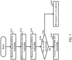
- FIG. 7 is a flowchart illustrating an operation example of terminal 200.
- terminal 200 receives and decodes, for example, DCI for PUSCH#A (DCI that schedules PUSCH#A) (S101).
- DCI for PUSCH#A DCI that schedules PUSCH#A
- Terminal 200 determines, for example, a slot that is available for PUSCH#A (S102).
- the slot that is available for PUSCH#A may be determined based on, for example, preconfiguration by RRC and DCI for PUSCH#A decoded in the processing of S101.
- Terminal 200 receives, for example, DCI for PUSCH#B (DCI for scheduling PUSCH#B), and decodes the DCI (S103).
- DCI for PUSCH#B DCI for scheduling PUSCH#B
- S103 decodes the DCI
- Terminal 200 determines, for example, whether the scheduling for PUSCH#A and PUSCH#B is out-of-order scheduling (S104). An example of a method for determining whether the scheduling is out-of-order scheduling will be described later.
- terminal 200 may transmit each of PUSCH#A and PUSCH#B (S105).
- terminal 200 In a case where the scheduling is determined to be Out-of-order scheduling (S104: Yes), the operation of terminal 200 (UE behavior) need not be defined (S106). Terminal 200 need not expect (or assume) the Out-of-order scheduling of the transmission of PUSCH#A and PUSCH#B, for example. For example, terminal 200 may determine the non-transmission of PUSCH#A and PUSCH#B in this case, or may determine the non-transmission of either one of PUSCH#A and PUSCH#B (for example, PUSCH#B).
- base station 100 may determine whether the scheduling for PUSCH#A and PUSCH#B is out-of-order scheduling, as in the case of terminal 200. For example, when base station 100 determines that the scheduling is not Out-of-order scheduling (or is In-order scheduling), base station 100 may actually perform the scheduling (for example, normal scheduling). Further, for example, in a case where base station 100 determines that the scheduling is Out-of-order scheduling, base station 100 need not perform the scheduling, or base station 100 may determine non-reception of PUSCH#A and PUSCH#B, or base station 100 may determine non-reception of one of PUSCH#A and PUSCH#B (for example, PUSCH#B).
- base station 100 may determine whether the scheduling for PUSCH#A and PUSCH#B is out-of-order scheduling, as in the case of terminal 200. For example, when base station 100 determines that the scheduling is not Out-of-order scheduling (or is In-order scheduling), base station 100 may actually perform the scheduling (for example, normal scheduling). Further,
- the transmission of PUSCH#A may be performed before the reception and the decoding of DCI for PUSCH#B (for example, the processing in S103).
- the criterion for determining whether PUSCH transmission is In-order scheduling or Out-of-order scheduling is, for example, "whether the PUSCH transmission#B is scheduled to be transmitted earlier than the end of PUSCH transmission#A (the end of the first PUSCH) in a case where the scheduling DCI of PUSCH transmission#A (for example, HARQ process ID#A or first PUSCH) is received temporally earlier than the scheduling DCI of PUSCH transmission#B (for example, HARQ process ID#B)."
- the scheduling may be determined to be Out-of-order scheduling. Further, for example, in a case where PUSCH transmission#B is scheduled to be transmitted later than the end of PUSCH transmission#A (the end of the first PUSCH), the scheduling may be determined to be In-order scheduling.
- the timing of the end of the PUSCH transmission#A (the end of the first PUSCH) as a criterion for determining whether the scheduling is Out-of-order scheduling may be determined based on an uplink slot that is available for PUSCH transmission#A (for example, repetition transmission of PUSCH#A).
- the timing of the end of the PUSCH transmission#A (the end of the first PUSCH) determined based on the uplink slot that is available for PUSCH transmission#A does not depend on an operation in which PUSCH is not transmitted (for example, an operation in which the PUSCH transmission is dropped) by a dynamic indication in any of the uplink slots that are available for PUSCH transmission#A.
- the timing at which PUSCH transmission#B is scheduled (or the timing at which PUSCH#B is scheduled to be transmitted) as a criterion for determining whether the scheduling is Out-of-order scheduling may be determined based on information (for example, the value of K2) related to the timing from a slot in which terminal 200 receives the DCI scheduling PUSCH transmission#B until terminal 200 receives PUSCH.
- terminal 200 determines that the scheduling is In-order scheduling.
- terminal 200 determines that the scheduling is Out-of-order scheduling (or is not In-order scheduling).
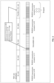
- FIG. 8 illustrates an example of Out-of-order scheduling and an example of normal scheduling (In-order scheduling).
- PUSCH repetition Type A with available slot counting with four times of Repetitions is applied to PUSCH#A is, and PUSCH repetition Type A with available slot counting with two times of Repetitions is applied to PUSCH#B. Further, in the example illustrated in FIG. 8 , the transmission of PUSCH transmission#A is dropped in Slot #8.
- the timing of the end of PUSCH transmission#A (the end of the first PUSCH) as a criterion for determining whether the scheduling is Out-of-order scheduling is determined based on an uplink slot available for PUSCH transmission#A, regardless of whether the transmission of PUSCH transmission#A is dropped or not.
- the uplink slots (UL slots) that are available for PUSCH transmission#A are Slots #3, #4, #7, and #8, and thus, the timing of the end of PUSCH transmission#A (the end of the first PUSCH) is Slot #8.
- Slot #8 may be configured as a criterion for determining whether the PUSCH transmission#A is Out-of-order scheduling.
- the timing at which PUSCH transmission#B is scheduled is Slot #9.
- terminal 200 determines that the scheduling is In-order scheduling.
- the timing at which PUSCH transmission#B is scheduled is Slot #8.
- the uplink slot that is available for PUSCH transmission in PUSCH repetition Type A with available slot counting can be determined depending on a slot format indication and information on a time resource allocation for PUSCH transmission configured in advance by RRC. Accordingly, terminal 200 is capable of determining, for example, the uplink slot that can be used for PUSCH transmission at the time of receiving (or decoding) DCI for scheduling the PUSCH. Meanwhile, whether PUSCH is actually transmitted in each of the uplink slots that are available for PUSCH transmission is determined for each slot by a dynamic indication.
- the timing of the end of PUSCH transmission#A (the end of the first PUSCH) as a criterion for determining whether the scheduling is Out-of-order scheduling, is determined based on the uplink slot that is available for PUSCH transmission#A.
- terminal 200 can determine the timing of the end of PUSCH transmission#A (the end of the first PUSCH) at the time when terminal 200 receives (or decodes) the DCI for scheduling PUSCH transmission#A.
- the timing of the end of PUSCH transmission#A (the end of the first PUSCH) as a criterion for determining whether the scheduling is Out-of-order scheduling is not dynamically updated after terminal 200 receives (or decodes) DCI for scheduling PUSCH transmission#A.
- terminal 200 can determine that the next normal PUSCH transmission to be allocated is scheduled later than the end of PUSCH transmission#A determined based on the uplink slot available for PUSCH transmission#A at the time when terminal 200 receives (or decodes) DCI for scheduling PUSCH transmission#A, for example. For this reason, the present embodiment has an advantage in that a process that terminal 200 determines whether the scheduling is Out-of-order scheduling can be simplified.
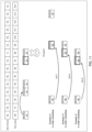
- FIG. 9 illustrates an example of Out-of-order scheduling and an example of normal scheduling (In-order scheduling).
- PUSCH repetition Type A with available slot counting with four times of Repetitions is applied to PUSCH#A
- PUSCH repetition Type A with available slot counting with two times of Repetitions is applied to PUSCH#B.
- Slot #7 and Slot #8 are uplink slots that are available for PUSCH transmission#A, while Slot #7 and Slot #8 are uplink slots that are not available for PUSCH transmission#B.
- Slot #7 and Slot #8 possibly include N symbols of the uplink symbols, are allocated a number of symbols less than or equal to N symbols for PUSCH transmission#A, and are allocated a number of symbols larger than N symbols for PUSCH transmission#B.
- PUSCH transmission#B is possibly deferred to the transmission from Slot #9 based on the uplink slot available for PUSCH transmission.
- the uplink slot for PUSCH transmission#B may be deferred from Slot #7 and Slot #8 to Slot #9 and Slot #13.
- the timing at which PUSCH transmission#B is scheduled which is a criterion for determining whether the scheduling is Out-of-order scheduling, may be determined based on information (for example, the value of K2) on the timing from the slot in which terminal 200 receives the DCI for scheduling PUSCH transmission#B until terminal 200 transmits PUSCH, regardless of whether the transmission of PUSCH transmission#B is deferred to a later slot.
- information for example, the value of K2
- the timing at which PUSCH transmission#B is scheduled is Slot #9, as illustrated in FIG. 9 .
- terminal 200 determines that the scheduling is In-order scheduling.
- the timing at which PUSCH transmission#B is scheduled is Slot #7.
- the timing at which PUSCH transmission#B is scheduled which is a criterion for determining whether the scheduling is Out-of-order scheduling, is determined based on information (for example, the value of K2) related to the timing from the slot in which terminal 200 receives the DCI for scheduling PUSCH transmission#B until terminal 200 transmits PUSCH, regardless of whether the transmission of PUSCH transmission#B is deferred to a later slot.
- the normal PUSCH transmission to be allocated after PUSCH transmission#A is scheduled later than the end of PUSCH transmission#A determined based on the uplink slot available for PUSCH transmission#A by K2.
- terminal 200 since the plurality of PUSCH allocations do not temporally overlap with each other, terminal 200 does not need to determine whether a certain slot is an uplink slot that is available for the plurality of PUSCH transmissions, and can specify the scheduling of one PUSCH transmission. Thus, there is an advantage in that the processing of terminal 200 can be simplified.
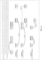
- FIG. 10 illustrates examples of Out-of-order scheduling and normal scheduling (In-order scheduling).
- PUSCH repetition Type A with available slot counting with four times of Repetitions is applied to PUSCH#A
- PUSCH repetition Type A with available slot counting with two times of Repetitions is applied to PUSCH#B.
- the transmission of PUSCH transmission#B is dropped in Slot #8.
- the timing at which PUSCH transmission#B is scheduled which is a criterion for determining whether the scheduling is Out-of-order scheduling, may be determined based on information (for example, the value of K2) on the timing from the slot in which terminal 200 receives the DCI for scheduling PUSCH transmission#B until terminal 200 transmits PUSCH, regardless of whether the transmission of PUSCH transmission#B is dropped.
- the timing at which PUSCH transmission#B is scheduled is Slot #9.
- terminal 200 determines that the scheduling is In-order scheduling.
- the uplink slot that is available for PUSCH transmission in PUSCH repetition Type A with available slot counting can be determined depending on a slot format indication and information on a time resource allocation for PUSCH transmission configured in advance by RRC. Accordingly, terminal 200 is capable of determining, for example, the uplink slot that can be used for PUSCH transmission at the time of receiving (or decoding) DCI for scheduling the PUSCH. Meanwhile, whether PUSCH is actually transmitted in each of the uplink slots that are available for PUSCH transmission is determined for each slot by a dynamic indication.
- the timing at which PUSCH transmission#B is scheduled which is a criterion for determining whether the scheduling is Out-of-order scheduling, can be determined at the time when DCI scheduling PUSCH transmission#B is received (or decoded). For this reason, the timing at which PUSCH transmission#B is scheduled, which is a criterion for determining whether the scheduling is an Out-of-order scheduling, is not dynamically updated after DCI scheduling PUSCH transmission#B is received (or decoded).
- terminal 200 can determine whether PUSCH transmission#B is Out-of-order scheduling at the time when terminal 200 receives (or decodes) DCI for scheduling PUSCH transmission#B, for example, and there is an advantage in that the processing in terminal 200 can be simplified.
- terminal 200 receives DCI (for example, PDCCH#A) scheduling PUSCH#A and receives DCI (for example, PDCCH#B) for scheduling PDSCH#B later than PDCCH#A for PUSCH#A and PUSCH#B at least one of which is repeatedly transmitted.
- terminal 200 determines whether the above-described scheduling is defined scheduling (for example, In-order scheduling) based on the timing for PDSCH transmission#A and the timing for PDSCH transmission#B.
- terminal 200 determines that the scheduling is Out-of-order scheduling, in other words, not In-order scheduling (for example, the defined scheduling).
- terminal 200 can appropriately determine whether the allocation of the PUSCH transmission is Out-of-order scheduling even in a case where PUSCH repetition Type A with available slot counting is applied to either of or both of the transmissions of PUSCH#A and PUSCH#B.
- terminal 200 can appropriately transmit a signal in the uplink.
- Configurations of base station 100 and terminal 200 according to the present embodiment may be the same as the configurations in Embodiment 1.
- the criterion for determining whether PUSCH transmission is In-order scheduling or Out-of-order scheduling is, for example, the same as in Embodiment 1, and is as follows: "whether the PUSCH transmission#B is scheduled to be transmitted earlier than the end of PUSCH transmission#A (the end of the first PUSCH) in a case where the scheduling DCI of PUSCH transmission#A (for example, HARQ process ID#A or first PUSCH) is received temporally earlier than the scheduling DCI of PUSCH transmission#B (for example, HARQ process ID#B)."
- the scheduling may be determined to be Out-of-order scheduling. Further, for example, when PUSCH transmission#B is scheduled to be transmitted later than the end of PUSCH transmission#A (the end of the first PUSCH), the scheduling may be determined to be In-order scheduling.
- the timing of the end of PUSCH transmission#A (the end of the first PUSCH), which serves as a criterion for determining whether the scheduling is Out-of-order scheduling, may be determined based on an uplink slot actually used for PUSCH transmission#A (for example, repetition transmission of PUSCH#A) (for example, the slot in which PUSCH#A is actually transmitted), for example.
- the timing of the end of PUSCH transmission#A (the end of the first PUSCH), which is determined based on the slot in which PUSCH#A is actually transmitted, may depend on an operation in which PUSCH transmission is not performed (for example, an operation in which PUSCH transmission is dropped) by dynamic indication in any uplink slot available for PUSCH transmission#A.
- the timing at which PUSCH transmission#B is scheduled (or the timing at which PUSCH#B is scheduled to be transmitted) as a criterion for determining whether the scheduling is Out-of-order scheduling may be determined based on information (for example, the value of K2) on the timing from the slot in which terminal 200 receives the DCI for scheduling PUSCH transmission#B until terminal 200 transmits PUSCH, as in Embodiment 1
- terminal 200 determines that the scheduling is In-order scheduling.
- terminal 200 determines that the scheduling is Out-of-order scheduling (or is not In-order scheduling).
- FIG. 11 illustrates an example of Out-of-order scheduling and normal scheduling (In-order scheduling).
- PUSCH repetition Type A with available slot counting with four times of Repetitions is applied to PUSCH#A
- PUSCH repetition Type A with available slot counting with two times of Repetitions is applied to PUSCH#B.
- the transmission of PUSCH transmission#A is dropped in Slot #8.
- the timing of the end of PUSCH transmission#A (the end of the first PUSCH) that serves as a criterion for determining whether the scheduling is Out-of-order scheduling is determined based on the actually transmitted PUSCH transmission#A depending on whether the transmission of PUSCH transmission#A is dropped.
- the uplink slots (UL slots) that are available for PUSCH transmission#A are Slots #3, #4, #7, and #8, and PUSCH transmission#A is dropped in Slot #8.
- the timing of the end of PUSCH transmission#A (the end of the first PUSCH) is the last Slot #7 among Slots #3, #4, and #7 which are actually used for transmission. Accordingly, Slot #7 may be set as a criterion for determining whether PUSCH transmission#A is Out-of-order scheduling.
- the timing at which PUSCH transmission#B is scheduled is Slot #9, as illustrated in FIG. 11 .
- terminal 200 determines that the scheduling is In-order scheduling.
- the timing at which PUSCH transmission#B is scheduled is Slot #8.
- terminal 200 determines that the scheduling is In-order scheduling.
- the timing at which PUSCH transmission#B is scheduled is Slot #7.
- the timing at which PUSCH transmission#B is scheduled is Slot #7.
- terminal 200 determines that the scheduling is Out-of-order scheduling.
- terminal 200 determines that the scheduling is Out-of-order scheduling, in other words, not In-order scheduling (for example, the defined scheduling).
- the timing of the end of PUSCH transmission#A (the end of the first PUSCH) and the timing at which PUSCH transmission#B is scheduled for determining whether the scheduling is Out-of-order scheduling are clearly defined in a case where PUSCH repetition Type A with available slot counting is applied to PUSCH transmission.
- terminal 200 can appropriately determine whether the allocation of the PUSCH transmission is Out-of-order scheduling.
- base station 100 and terminal 200 according to the present embodiment may be the same as those in Embodiment 1.
- the criterion for determining whether PUSCH transmission is In-order scheduling or Out-of-order scheduling is, for example, the same as in Embodiment 1, and is as follows: "whether the PUSCH transmission#B is scheduled to be transmitted earlier than the end of PUSCH transmission#A (the end of the first PUSCH) in a case where the scheduling DCI of PUSCH transmission#A (for example, HARQ process ID#A or first PUSCH) is received temporally earlier than the scheduling DCI of PUSCH transmission#B (for example, HARQ process ID#B)."
- the scheduling may be determined to be Out-of-order scheduling. Further, for example, when PUSCH transmission#B is scheduled to be transmitted later than the end of PUSCH transmission#A (the end of the first PUSCH), the scheduling may be determined to be In-order scheduling.
- the timing of the end of the PUSCH transmission#A (the end of the first PUSCH) as a criterion for determining whether the scheduling is Out-of-order scheduling may be determined based on the uplink slot available for PUSCH transmission#A (for example, repetition transmission of PUSCH#A), in the same manner as in Embodiment 1.
- the timing of the end of the PUSCH transmission#A (the end of the first PUSCH) that is determined based on the uplink slot that is available for PUSCH transmission#A does not depend on an operation in which PUSCH is not transmitted (for example, an operation in which the PUSCH transmission is dropped) by a dynamic indication in any of the uplink slots that are available for PUSCH transmission#A.
- the timing at which PUSCH transmission#B is scheduled which is a criterion for determining whether the scheduling is Out-of-order scheduling, may be determined based on an uplink slot available for PUSCH transmission#B (for example, repetition transmission of PUSCH#B), for example.
- terminal 200 determines that the scheduling is In-order scheduling.
- terminal 200 determines that the scheduling is Out-of-order scheduling (or is not In-order scheduling).
- FIG. 12 illustrates an example of Out-of- order scheduling and a normal scheduling (In-order scheduling).
- PUSCH repetition Type A with available slot counting with four times of Repetitions is applied to PUSCH#A
- PUSCH repetition Type A with available slot counting with two times of Repetitions is applied to PUSCH#B.
- Slot #7 and Slot #8 are uplink slots that are available for PUSCH transmission#A, while Slot #7 and Slot #8 are uplink slots that are not available for PUSCH transmission#B.
- Slot #7 and Slot #8 possibly include N symbols of the uplink symbols, are allocated a number of symbols less than or equal to N symbols for PUSCH transmission#A, and are allocated a number of symbols larger than N symbols for PUSCH transmission#B.
- the timing of the end of PUSCH transmission#A is determined based on the uplink slot available for PUSCH transmission#A.
- the uplink slots (UL slots) that can be used for PUSCH transmission#A are Slots #3, #4, #7, and #8, and thus, the timing of the end of PUSCH transmission#A (the end of the first PUSCH) is Slot #8.
- Slot #8 may be set as a criterion for determining whether the PUSCH transmission#A is Out-of-order scheduling.
- the uplink slots available for PUSCH transmission#B are Slots #9 and #13, as illustrated in FIG. 12 .
- Slot #9 may be set as a criterion for determining whether PUSCH transmission#B is an Out-of-order scheduling or not.
- the uplink slot that is available for PUSCH transmission#B is a timing later than the end of PUSCH transmission#A (the end of the first PUSCH: Slot #8), and thus, terminal 200 determines that the scheduling is In-order scheduling.
- the uplink slots that are available for PUSCH transmission#B may be configured as Slots #9 and #13 (or may be deferred). Accordingly, Slot #9 may be set as a criterion for determining whether PUSCH transmission#B is Out-of-order scheduling.
- the uplink slot that is available for PUSCH transmission#B is a timing later than the end of PUSCH transmission#A (the end of the first PUSCH: Slot #8), and thus, terminal 200 determines that the scheduling is In-order scheduling.
- the uplink slots that are available for PUSCH transmission#B may be configured as Slots #4 and #9 (or may be partially deferred). Accordingly, Slot #4 may be configured as a criterion for determining whether PUSCH transmission#B is Out-of-order scheduling or not. In this case, the uplink slot that is available for PUSCH transmission#B is at a timing earlier than the end of the PUSCH transmission#A (the end of the first PUSCH: Slot #8), and thus, terminal 200 determines that the scheduling is Out-of-order scheduling.
- terminal 200 determines that the scheduling is not In-order scheduling (for example, a defined scheduling), in other words, the scheduling is Out-of-order scheduling.
- the timing of the end of PUSCH transmission#A (the end of the first PUSCH) and the timing at which PUSCH transmission#B is scheduled for determining whether the scheduling is Out-of-order scheduling are clearly defined.
- terminal 200 can appropriately determine whether the allocation of the PUSCH transmission is Out-of-order scheduling.
- the uplink slot that is available for PUSCH transmission#B is configured as a criterion for determining whether the scheduling is Out-of-order scheduling, and thus, the allocation of PUSCH transmission#B is possible such that the scheduling is not Out-of-order scheduling even in a case where the value that may be indicated by the value of K2 is within a narrow range.
- the uplink slot that is available for PUSCH transmission#B is configured as a criterion for determining whether the scheduling is Out-of-order scheduling, and thus, the allocation of PUSCH transmission#B is possible such that the scheduling is not Out-of-order scheduling even in a case where the value that may be indicated by the value of K2 is within a narrow range.
- base station 100 and terminal 200 according to the present embodiment may be the same as those in Embodiment 1.
- the criterion for determining whether PUSCH transmission is In-order scheduling or Out-of-order scheduling is, for example, the same as in Embodiment 1, and is as follows: "whether the PUSCH transmission#B is scheduled to be transmitted earlier than the end of PUSCH transmission#A (the end of the first PUSCH) in a case where the scheduling DCI of PUSCH transmission#A (for example, HARQ process ID#A or first PUSCH) is received temporally earlier than the scheduling DCI of PUSCH transmission#B (for example, HARQ process ID#B)."
- the scheduling may be determined to be Out-of-order scheduling. Further, for example, when PUSCH transmission#B is scheduled to be transmitted later than the end of PUSCH transmission#A (the end of the first PUSCH), the scheduling may be determined to be In-order scheduling.
- the timing of the end (the end of the first PUSCH) of the PUSCH transmission#A as a criterion for determining whether the scheduling is Out-of-order scheduling may be determined based on the uplink slot available for PUSCH transmission#A (for example, repetition transmission of PUSCH#A), in the same manner as in Embodiment 1.
- the timing of the end of the PUSCH transmission#A (the end of the first PUSCH) that is determined based on the uplink slot that is available for PUSCH transmission#A does not depend on an operation in which PUSCH is not transmitted (for example, an operation in which the PUSCH transmission is dropped) by a dynamic indication in any of the uplink slots that are available for PUSCH transmission#A.
- the timing at which PUSCH transmission#B is scheduled may be determined based on an uplink slot actually used for PUSCH transmission#B (for example, repetition transmission of PUSCH#B) (or the slot in which PUSCH#B is actually transmitted),.
- terminal 200 determines that the scheduling is In-order scheduling.
- terminal 200 determines that the scheduling is Out-of-order scheduling (or is not In-order scheduling).
- FIG. 13 illustrates an example of Out-of-order scheduling and normal scheduling (In-order scheduling).
- PUSCH repetition Type A with available slot counting with four times of Repetitions is applied to PUSCH#A
- PUSCH repetition Type A with available slot counting with two times of Repetitions is applied to PUSCH#B.
- the transmission of PUSCH transmission#B is dropped in Slot #7 or Slot #8.
- the timing of the end of PUSCH transmission#A (the end of the first PUSCH) that serves as a criterion for determining whether the scheduling is Out-of-order scheduling is determined based on an uplink slot available for PUSCH transmission#A, regardless of whether the transmission of the PUSCH transmission#A is dropped.
- the uplink slots (UL slots) that can be used for PUSCH transmission#A are Slots #3, #4, #7, and #8, and thus, the timing of the end of the PUSCH transmission#A (the end of the first PUSCH) is Slot #8. Accordingly, Slot #8 may be set as a criterion for determining whether the scheduling is Out-of-order scheduling for PUSCH transmission#A.
- the uplink slots actually used for PUSCH transmission#B are Slots #9 and #13, as illustrated in FIG. 13 .
- Slot #9 may be set as a criterion for determining whether the scheduling is Out-of-order scheduling for PUSCH transmission#B.
- Slot #9, which is actually used for PUSCH transmission#B is a timing later than the end of PUSCH transmission#A (the end of the first PUSCH: Slot #8), and thus, terminal 200 determines that the scheduling is In-order scheduling.
- Slot #9 may be set as a criterion for determining whether the scheduling is Out-of-order scheduling for PUSCH transmission#B.
- Slot #9 which is actually used for PUSCH transmission#B, is a timing later than the end of PUSCH transmission#A (the end of the first PUSCH: Slot #8), and thus, terminal 200 determines that the scheduling is In-order scheduling.
- Slot #4 may be configured as a criterion for determining whether the scheduling is Out-of-order scheduling for PUSCH transmission#B.
- Slot #4 which is actually used for PUSCH transmission#B, is a timing earlier than the end of PUSCH transmission#A (the end of the first PUSCH: Slot #8), and thus, terminal 200 determines that the scheduling is Out-of-order scheduling.
- terminal 200 determines that the scheduling is not In-order scheduling (for example, a defined scheduling), that is, the scheduling is Out-of-order scheduling.
- the timing of the end of PUSCH transmission#A (the end of the first PUSCH) and the timing at which PUSCH transmission#B is scheduled for determining whether the scheduling is Out-of-order scheduling are clearly defined.
- terminal 200 can appropriately determine whether the allocation of the PUSCH transmission is Out-of-order scheduling.
- the uplink slot actually used for PUSCH transmission#B is configured as a criterion for determining whether the scheduling is Out-of-order scheduling or not, and thus, the allocation of PUSCH transmission#B is made possible such that the scheduling is not Out-of-order scheduling even in a case where the range of values that can be indicated by the value of K2 is narrow.
- the uplink slot actually used for PUSCH transmission#B is configured as a criterion for determining whether the scheduling is Out-of-order scheduling or not, and thus, the allocation of PUSCH transmission#B is made possible such that the scheduling is not Out-of-order scheduling even in a case where the range of values that can be indicated by the value of K2 is narrow.
- PUSCH overlapping the case where PUSCH transmission#A and PUSCH transmission#B are scheduled to temporally overlap with each other for any two HARQ process ID#A and HARQ process ID#B will be referred to as "PUSCH overlapping.”
- the UE is not expected to transmit a PUSCH that overlaps in time with another PUSCH.
- terminal 200 does not assume PUSCH overlapping, the terminal operation in a case of PUSCH overlapping is not defined in the standard. For this reason, base station 100 is expected to schedule PUSCH such that PUSCH overlapping does not occur, for example.
- terminal 200 determines whether PUSCH overlapping occurs, based on whether the transmission of PUSCH#A determined based on the uplink slot available for PUSCH transmission#A and the transmission of another PUSCH different from PUSCH#A temporally overlap with each other.
- the timing of PUSCH transmission#A determined based on the uplink slot available for PUSCH transmission#A need not depend on an operation in which PUSCH is not transmitted (for example, an operation in which PUSCH transmission is dropped) by the dynamic indication.
- terminal 200 may determine whether the PUSCH overlapping occurs, based on whether the actual transmission of PUSCH transmission#A (for example, the slot actually used) and the transmission of another PUSCH different from PUSCH#A temporally overlap with each other.
- PUSCH transmission#A for example, the slot actually used
- the timing at which transmission of another PUSCH different from PUSCH#A is scheduled may be determined based on information (for example, a value of K2) related to the timing from the slot in which the DCI for scheduling the PUSCH transmission is received until PUSCH is transmitted, an uplink slot that is available for the PUSCH transmission, or an uplink slot that is actually used for the PUSCH transmission.
- information for example, a value of K2 related to the timing from the slot in which the DCI for scheduling the PUSCH transmission is received until PUSCH is transmitted, an uplink slot that is available for the PUSCH transmission, or an uplink slot that is actually used for the PUSCH transmission.
- the unit of Repetition is not limited to the slot unit, and may be, for example, a mini-slot (sub-slot) unit obtained by dividing a slot into a plurality of units, a multi-slot unit constituted by a plurality of slots, or a symbol unit.
- the number of PUSCHs which is a determination target for Out-of-order scheduling, is not limited to two.
- the embodiment described above may also be applied to a case where the number of PUSCHs are three or more. In a case where the number of PUSCHs is three or more, the above-described embodiment may be applied to continuous two PUSCHs in an order in which terminal 200 receives DCI scheduling PUSCH.
- the timing of the end of PUSCH transmission#A (the end of the first PUSCH) that serves as a criterion for determining whether the scheduling is Out-of-order scheduling when PUSCH repetition Type A with available slot counting is applied to PUSCH transmission#A is either an uplink slot that is available for PUSCH transmission#A (for example, Embodiment 1, Embodiment 3, or Embodiment 4) or an uplink slot that is actually used for PUSCH transmission#A (for example, Embodiment 2).
- the timing at which PUSCH transmission#B is scheduled which serves as a criterion for determining whether the scheduling is Out-of-order scheduling, when PUSCH repetition Type A with available slot counting is applied to PUSCH transmission#B is any one of a timing based on the value of K2 (for example, Embodiment 1 or Embodiment 2), an uplink slot that is available for PUSCH transmission#B (for example, Embodiment 3), or an uplink slot that is actually used for PUSCH transmission#B (for example, Embodiment 4).
- K2 for example, Embodiment 1 or Embodiment 2
- an uplink slot that is available for PUSCH transmission#B for example, Embodiment 3
- an uplink slot that is actually used for PUSCH transmission#B for example, Embodiment 4
- the timing at which the end of the PUSCH transmission#A (the end of the first PUSCH) and the timing at which PUSCH transmission#B is scheduled, which serves as criteria for determining whether the scheduling is Out-of-order scheduling, may be set to any of the above-described timings.
- an uplink slot that is available for PUSCH transmission#B (for example, Embodiment 3), or an uplink slot that is actually used for PUSCH transmission#B (for example, Embodiment 4) may be applied to the timing at which PUSCH transmission#B is scheduled, which serves as a criterion for determining whether the scheduling is Out-of-order scheduling.
- terminal 200 may determine that the scheduling is Out-of-order scheduling (or is not In-order scheduling).
- terminal 200 may determine that the scheduling is Out-of-order scheduling (or not In-order scheduling).
- PUSCH transmission is described as an uplink transmission, but the channel used for the uplink transmission is not limited to PUSCH, and may be another channel. Further, the type of information to be transmitted is not limited to data, and may be information of another type (for example, an uplink control signal). Further, an exemplary embodiment of the present disclosure is not limited to the uplink transmission, but may be applied to downlink transmission or sidelink transmission.
- the parameters such as the number of slots, the number of symbols, symbol positions, the value of K2, the number of repetitions, and the like, which have been illustrated in the present disclosure, are merely examples, and may have other values.
- Repetition may also be referred to as, for example, slot aggregation, slot bundling, TTI aggregation, or TTI bundling.
- the present disclosure may be applied to, for example, communication between terminals, such as a sidelink communication.
- a downlink control channel, a downlink data channel, an uplink control channel, and an uplink data channel are not limited to PDCCH, PDSCH, PUCCH, and PUSCH, respectively, and may be control channels having other names.
- the RRC signaling is assumed for the higher layer signaling, but the signaling may be replaced with Medium Access Control (MAC) signaling and indication by a DCI that is physical layer signaling.
- MAC Medium Access Control
- Information indicating whether terminal 200 supports the functions, operations, or pieces of processing that have been indicated in the above-mentioned embodiments and complements may be transmitted (or indicated) from terminal 200 to base station 100, as capability information or a capability parameter for terminal 200, for example.
- the capability information may include information elements (IEs) that individually indicate whether terminal 200 supports at least one of the functions, operations, or pieces of processing that have been described in the above-mentioned embodiments, variations, and complements.
- the capability information may include information elements that indicate whether terminal 200 supports a combination of any two or more of the functions, operations, or pieces of processing that have been described in the above-mentioned embodiments, variations, and complements.
- Base station 100 may determine (or decide or assume), for example, based on the capability information received from terminal 200, the functions, operations, or processes that are supported (or not supported) by terminal 200, which is a transmission source of the capability information. Base station 100 may execute operations, processes, or control in accordance with a determination result based on the capability information. For example, base station 100 may control uplink-related processing based on the capability information received from terminal 200.
- terminal 200 does not entirely support the functions, operations, or pieces of processing described in the above-mentioned embodiments, variations, and complements, such an unsupported part of the functions, operations, or processes may be interpreted as a limitation in terminal 200.
- information or a request relating to such limitation may be indicated to base station 100.
- the information on the capability or the limitation of terminal 200 may be defined by standards or may be implicitly indicated to base station 100 in association with information known in base station 100 or information to be transmitted to base station 100, for example.
- the present disclosure may be applied to any of uplink, downlink and sidelink.
- the present disclosure may be applied to, for example, uplink channels, such as PUSCH, PUCCH, and PRACH, downlink channels, such as PDSCH, PDCCH, and PBCH, and side link channels, such as Physical Sidelink Shared Channel (PSSCH), Physical Sidelink Control Channel (PSCCH), and Physical Sidelink Broadcast Channel (PSBCH).
- uplink channels such as PUSCH, PUCCH, and PRACH
- downlink channels such as PDSCH, PDCCH, and PBCH
- side link channels such as Physical Sidelink Shared Channel (PSSCH), Physical Sidelink Control Channel (PSCCH), and Physical Sidelink Broadcast Channel (PSBCH).
- PSSCH Physical Sidelink Shared Channel
- PSCCH Physical Sidelink Control Channel
- PSBCH Physical Sidelink Broadcast Channel
- PDCCH, PDSCH, PUSCH, and PUCCH are examples of a downlink control channel, a downlink data channel, an uplink data channel, and an uplink control channel, respectively.
- PSCCH and PSSCH are examples of a sidelink control channel and a sidelink data channel, respectively.
- PBCH and PSBCH are examples of broadcast channels, respectively, and PRACH is an example of a random access channel.
- the present disclosure may be applied to any of data channels and control channels.
- the channels in the present disclosure may be replaced with data channels including PDSCH, PUSCH and PSSCH and/or control channels including PDCCH, PUCCH, PBCH, PSCCH, and PSBCH.
- the reference signals are signals known to both a base station and a mobile station and each reference signal may be referred to as a Reference Signal (RS) or sometimes a pilot signal.
- the reference signal may be any of a DMRS, a Channel State Information - Reference Signal (CSI-RS), a Tracking Reference Signal (TRS), a Phase Tracking Reference Signal (PTRS), a Cell-specific Reference Signal (CRS), and a Sounding Reference Signal (SRS).
- CSI-RS Channel State Information - Reference Signal
- TRS Tracking Reference Signal
- PTRS Phase Tracking Reference Signal
- CRS Cell-specific Reference Signal
- SRS Sounding Reference Signal
- time resource units are not limited to one or a combination of slots and symbols, and may be time resource units, such as frames, superframes, subframes, slots, time slots, subslots, minislots, or time resource units, such as symbols, Orthogonal Frequency Division Multiplexing (OFDM) symbols, Single Carrier-Frequency Division Multiple Access (SC-FDMA) symbols, or other time resource units.
- time resource units such as frames, superframes, subframes, slots, time slots, subslots, minislots, or time resource units, such as symbols, Orthogonal Frequency Division Multiplexing (OFDM) symbols, Single Carrier-Frequency Division Multiple Access (SC-FDMA) symbols, or other time resource units.
- OFDM Orthogonal Frequency Division Multiplexing
- SC-FDMA Single Carrier-Frequency Division Multiple Access
- the present disclosure may be applied to any of a licensed band and an unlicensed band.
- the present disclosure may be applied to any of communication between a base station and a terminal (Uu-link communication), communication between a terminal and a terminal (Sidelink communication), and Vehicle to Everything (V2X) communication.
- the channels in the present disclosure may be replaced with PSCCH, PSSCH, Physical Sidelink Feedback Channel (PSFCH), PSBCH, PDCCH, PUCCH, PDSCH, PUSCH, and PBCH.
- the present disclosure may be applied to any of a terrestrial network or a network other than a terrestrial network (NTN: Non-Terrestrial Network) using a satellite or a High Altitude Pseudo Satellite (HAPS).
- NTN Non-Terrestrial Network
- HAPS High Altitude Pseudo Satellite
- the present disclosure may be applied to a network having a large cell size, and a terrestrial network with a large delay compared with a symbol length or a slot length, such as an ultra-wideband transmission network.
- An antenna port refers to a logical antenna (antenna group) formed of one or more physical antenna(s). That is, the antenna port does not necessarily refer to one physical antenna and sometimes refers to an array antenna formed of multiple antennas or the like. For example, it is not defined how many physical antennas form the antenna port, and instead, the antenna port is defined as the minimum unit through which a terminal is allowed to transmit a reference signal. The antenna port may also be defined as the minimum unit for multiplication of a precoding vector weighting.
- 5G 5th generation cellular technology
- NR new radio access technology
- the first version of the 5G standard was completed at the end of 2017, which allows proceeding to 5G NR standard-compliant trials and commercial deployments of terminals (e.g., smartphones).
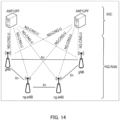
- the overall system architecture assumes an NG-RAN (Next Generation-Radio Access Network) that includes gNBs, providing the NG-radio access user plane (SDAP/PDCP/RLC/MAC/PHY) and control plane (RRC) protocol terminations towards the UE.
- NG-RAN Next Generation-Radio Access Network
- the gNBs are interconnected with each other by means of the Xn interface.
- the gNBs are also connected by means of the Next Generation (NG) interface to the NGC (Next Generation Core), more specifically to the AMF (Access and Mobility Management Function) (e.g., a particular core entity performing the AMF) by means of the NG-C interface and to the UPF (User Plane Function) (e.g., a particular core entity performing the UPF) by means of the NG-U interface.
- the NG-RAN architecture is illustrated in FIG. 14 (see e.g., 3GPP TS 38.300 v15.6.0, section 4).
- the user plane protocol stack for NR includes the PDCP (Packet Data Convergence Protocol, see clause 6.4 of TS 38.300), RLC (Radio Link Control, see clause 6.3 of TS 38.300) and MAC (Medium Access Control, see clause 6.2 of TS 38.300) sublayers, which are terminated in the gNB on the network side. Additionally, a new Access Stratum (AS) sublayer (SDAP, Service Data Adaptation Protocol) is introduced above the PDCP (see e.g., clause 6.5 of 3GPP TS 38.300 ).
- a control plane protocol stack is also defined for NR (see for instance TS 38.300, section 4.4.2).
- the Medium Access Control layer handles logical-channel multiplexing, and scheduling and scheduling-related functions, including handling of different numerologies.
- the physical layer is for example responsible for coding, PHY HARQ processing, modulation, multi-antenna processing, and mapping of the signal to the appropriate physical time-frequency resources.
- the physical layer also handles mapping of transport channels to physical channels.
- the physical layer provides services to the MAC layer in the form of transport channels.
- a physical channel corresponds to the set of time-frequency resources used for transmission of a particular transport channel, and each transport channel is mapped to a corresponding physical channel.
- Examples of the physical channel include a Physical Random Access Channel (PRACH), a Physical Uplink Shared Channel (PUSCH), and a Physical Uplink Control Channel (PUCCH) as uplink physical channels, and a Physical Downlink Shared Channel (PDSCH), a Physical Downlink Control Channel (PDCCH), and a Physical Broadcast Channel (PBCH) as downlink physical channels.
- PRACH Physical Random Access Channel
- PUSCH Physical Uplink Shared Channel
- PUCCH Physical Uplink Control Channel
- PDSCH Physical Downlink Shared Channel
- PDCCH Physical Downlink Control Channel
- PBCH Physical Broadcast Channel
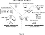
- Use cases/deployment scenarios for NR could include enhanced mobile broadband (eMBB), ultra-reliable low-latency communications (URLLC), and massive machine type communication (mMTC), which have diverse requirements in terms of data rates, latency, and coverage.
- eMBB enhanced mobile broadband
- URLLC ultra-reliable low-latency communications
- mMTC massive machine type communication
- eMBB is expected to support peak data rates (20 Gbps for downlink and 10 Gbps for uplink) and user-experienced data rates on the order of three times what is offered by IMT-Advanced.
- URLLC the tighter requirements are put on ultra-low latency (0.5 ms for UL and DL each for user plane latency) and high reliability (1-10-5 within 1 ms).
- mMTC may preferably require high connection density (1,000,000 devices/km 2 in an urban environment), large coverage in harsh environments, and extremely long-life battery for low cost devices (15 years).
- the OFDM numerology e.g., subcarrier spacing, OFDM symbol duration, cyclic prefix (CP) duration, and number of symbols per scheduling interval
- low-latency services may preferably require a shorter symbol duration (and thus larger subcarrier spacing) and/or fewer symbols per scheduling interval (aka, TTI) than an mMTC service.
- deployment scenarios with large channel delay spreads may preferably require a longer CP duration than scenarios with short delay spreads.
- the subcarrier spacing should be optimized accordingly to retain the similar CP overhead.
- NR may support more than one value of subcarrier spacing.
- the term "resource element" can be used to denote a minimum resource unit being composed of one subcarrier for the length of one OFDM/SC-FDMA symbol.
- resource grids of subcarriers and OFDM symbols are defined respectively for uplink and downlink.
- Each element in the resource grids is called a resource element and is identified based on the frequency index in the frequency domain and the symbol position in the time domain (see 3GPP TS 38.211 v15.6.0).
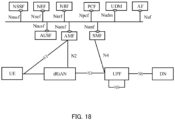
- FIG. 15 illustrates the functional split between the NG-RAN and the 5GC.
- a logical node of the NG-RAN is gNB or ng-eNB.
- the 5GC includes logical nodes AMF, UPF, and SMF.
- gNB and ng-eNB hosts the following main functions:
- the Access and Mobility Management Function hosts the following main functions:
- UPF User Plane Function
- Session Management Function hosts the following main functions:
- FIG. 16 illustrates some interactions between a UE, gNB, and AMF (a 5GC Entity) performed in the context of a transition of the UE from RRC_IDLE to RRC_CONNECTED for the NAS part (see TS 38 300 v15.6.0).
- AMF a 5GC Entity
Landscapes
- Engineering & Computer Science (AREA)
- Computer Networks & Wireless Communication (AREA)
- Signal Processing (AREA)
- Mobile Radio Communication Systems (AREA)
Applications Claiming Priority (2)
| Application Number | Priority Date | Filing Date | Title |
|---|---|---|---|
| JP2022070126 | 2022-04-21 | ||
| PCT/JP2023/010997 WO2023203938A1 (fr) | 2022-04-21 | 2023-03-20 | Terminal, station de base, procédé de communication, et circuit intégré |
Publications (2)
| Publication Number | Publication Date |
|---|---|
| EP4514029A1 true EP4514029A1 (fr) | 2025-02-26 |
| EP4514029A4 EP4514029A4 (fr) | 2025-08-20 |
Family
ID=88419714
Family Applications (1)
| Application Number | Title | Priority Date | Filing Date |
|---|---|---|---|
| EP23791591.3A Pending EP4514029A4 (fr) | 2022-04-21 | 2023-03-20 | Terminal, station de base, procédé de communication, et circuit intégré |
Country Status (6)
| Country | Link |
|---|---|
| US (1) | US20250330958A1 (fr) |
| EP (1) | EP4514029A4 (fr) |
| JP (1) | JPWO2023203938A1 (fr) |
| CN (1) | CN119054390A (fr) |
| TW (1) | TW202406392A (fr) |
| WO (1) | WO2023203938A1 (fr) |
Family Cites Families (1)
| Publication number | Priority date | Publication date | Assignee | Title |
|---|---|---|---|---|
| JP7537988B2 (ja) | 2020-10-26 | 2024-08-21 | 花王株式会社 | インクジェット印刷用水系インク |
-
2023
- 2023-03-20 EP EP23791591.3A patent/EP4514029A4/fr active Pending
- 2023-03-20 WO PCT/JP2023/010997 patent/WO2023203938A1/fr not_active Ceased
- 2023-03-20 CN CN202380035035.6A patent/CN119054390A/zh active Pending
- 2023-03-20 JP JP2024516138A patent/JPWO2023203938A1/ja active Pending
- 2023-03-20 US US18/855,273 patent/US20250330958A1/en active Pending
- 2023-04-12 TW TW112113676A patent/TW202406392A/zh unknown
Also Published As
| Publication number | Publication date |
|---|---|
| CN119054390A (zh) | 2024-11-29 |
| TW202406392A (zh) | 2024-02-01 |
| US20250330958A1 (en) | 2025-10-23 |
| JPWO2023203938A1 (fr) | 2023-10-26 |
| EP4514029A4 (fr) | 2025-08-20 |
| WO2023203938A1 (fr) | 2023-10-26 |
Similar Documents
| Publication | Publication Date | Title |
|---|---|---|
| US12609852B2 (en) | Terminal and communication method using semi-static physical uplink control channel (PUCCH) resource configuration | |
| US12563557B2 (en) | Terminal, base station, and communication method | |
| US20230261830A1 (en) | Terminal, base station, and communication method | |
| EP4383659A1 (fr) | Dispositif et procédé de communication | |
| EP4185044B1 (fr) | Terminal, station de base et procédé de communication | |
| US20250247831A1 (en) | Base station, terminal, and communication method | |
| EP4319382A1 (fr) | Dispositif de communication et procédé de communication | |
| EP4322661A1 (fr) | Terminal, station de base et procédé de communication | |
| US20230308330A1 (en) | Terminal, base station, and communication method | |
| EP4618639A1 (fr) | Terminal, station de base et procédé de communication | |
| EP4456641A1 (fr) | Dispositif de communication et procédé de communication | |
| EP4542945A1 (fr) | Terminal, station de base et procédé de communication | |
| EP4503481A1 (fr) | Terminal, station de base et procédé de communication | |
| EP4383906A1 (fr) | Terminal, station de base et procédé de communication | |
| US20250056511A1 (en) | Base station, terminal and communication method | |
| US20240357586A1 (en) | Joint channel estimation for multiple transport blocks | |
| EP4340493A1 (fr) | Dispositif de communication et procédé de communication | |
| EP4514029A1 (fr) | Terminal, station de base, procédé de communication, et circuit intégré | |
| EP4503482A1 (fr) | Terminal, station de base, et procédé de communication | |
| EP4503483A1 (fr) | Terminal, station de base, et procédé de communication | |
| EP4668904A1 (fr) | Terminal, station de base, procédé de communication et circuit intégré | |
| EP4615135A1 (fr) | Terminal, station de base, procédé de communication et circuit intégré | |
| EP4618683A1 (fr) | Terminal, station de base, et procédé de communication | |
| EP4572487A1 (fr) | Terminal, station de base et procédé de communication | |
| EP4564974A1 (fr) | Terminal, station de base, et procédé de communication |
Legal Events
| Date | Code | Title | Description |
|---|---|---|---|
| STAA | Information on the status of an ep patent application or granted ep patent |
Free format text: STATUS: THE INTERNATIONAL PUBLICATION HAS BEEN MADE |
|
| PUAI | Public reference made under article 153(3) epc to a published international application that has entered the european phase |
Free format text: ORIGINAL CODE: 0009012 |
|
| STAA | Information on the status of an ep patent application or granted ep patent |
Free format text: STATUS: REQUEST FOR EXAMINATION WAS MADE |
|
| 17P | Request for examination filed |
Effective date: 20240926 |
|
| AK | Designated contracting states |
Kind code of ref document: A1 Designated state(s): AL AT BE BG CH CY CZ DE DK EE ES FI FR GB GR HR HU IE IS IT LI LT LU LV MC ME MK MT NL NO PL PT RO RS SE SI SK SM TR |
|
| REG | Reference to a national code |
Ref country code: DE Ref legal event code: R079 Free format text: PREVIOUS MAIN CLASS: H04W0072126800 Ipc: H04L0001186700 |
|
| DAV | Request for validation of the european patent (deleted) | ||
| DAX | Request for extension of the european patent (deleted) | ||
| A4 | Supplementary search report drawn up and despatched |
Effective date: 20250717 |
|
| RIC1 | Information provided on ipc code assigned before grant |
Ipc: H04L 1/1867 20230101AFI20250711BHEP Ipc: H04L 1/08 20060101ALI20250711BHEP Ipc: H04W 72/1268 20230101ALI20250711BHEP |