EP4514044A1 - Verfahren und vorrichtung zum senden oder empfangen eines klangreferenzsignals in einem drahtloskommunikationssystem - Google Patents
Verfahren und vorrichtung zum senden oder empfangen eines klangreferenzsignals in einem drahtloskommunikationssystem Download PDFInfo
- Publication number
- EP4514044A1 EP4514044A1 EP23792064.0A EP23792064A EP4514044A1 EP 4514044 A1 EP4514044 A1 EP 4514044A1 EP 23792064 A EP23792064 A EP 23792064A EP 4514044 A1 EP4514044 A1 EP 4514044A1
- Authority
- EP
- European Patent Office
- Prior art keywords
- srs
- rrc
- transmission
- sdt
- positioning
- Prior art date
- Legal status (The legal status is an assumption and is not a legal conclusion. Google has not performed a legal analysis and makes no representation as to the accuracy of the status listed.)
- Pending
Links
Images


Classifications
-
- H—ELECTRICITY
- H04—ELECTRIC COMMUNICATION TECHNIQUE
- H04W—WIRELESS COMMUNICATION NETWORKS
- H04W64/00—Locating users or terminals or network equipment for network management purposes, e.g. mobility management
-
- H—ELECTRICITY
- H04—ELECTRIC COMMUNICATION TECHNIQUE
- H04L—TRANSMISSION OF DIGITAL INFORMATION, e.g. TELEGRAPHIC COMMUNICATION
- H04L5/00—Arrangements affording multiple use of the transmission path
- H04L5/003—Arrangements for allocating sub-channels of the transmission path
- H04L5/0048—Allocation of pilot signals, i.e. of signals known to the receiver
- H04L5/0051—Allocation of pilot signals, i.e. of signals known to the receiver of dedicated pilots, i.e. pilots destined for a single user or terminal
-
- H—ELECTRICITY
- H04—ELECTRIC COMMUNICATION TECHNIQUE
- H04L—TRANSMISSION OF DIGITAL INFORMATION, e.g. TELEGRAPHIC COMMUNICATION
- H04L5/00—Arrangements affording multiple use of the transmission path
- H04L5/0091—Signalling for the administration of the divided path, e.g. signalling of configuration information
- H04L5/0094—Indication of how sub-channels of the path are allocated
-
- H—ELECTRICITY
- H04—ELECTRIC COMMUNICATION TECHNIQUE
- H04W—WIRELESS COMMUNICATION NETWORKS
- H04W74/00—Wireless channel access
- H04W74/08—Non-scheduled access, e.g. ALOHA
- H04W74/0833—Random access procedures, e.g. with 4-step access
- H04W74/0841—Random access procedures, e.g. with 4-step access with collision treatment
- H04W74/0858—Random access procedures, e.g. with 4-step access with collision treatment collision detection
-
- H—ELECTRICITY
- H04—ELECTRIC COMMUNICATION TECHNIQUE
- H04W—WIRELESS COMMUNICATION NETWORKS
- H04W74/00—Wireless channel access
- H04W74/08—Non-scheduled access, e.g. ALOHA
- H04W74/0866—Non-scheduled access, e.g. ALOHA using a dedicated channel for access
- H04W74/0875—Non-scheduled access, e.g. ALOHA using a dedicated channel for access with assigned priorities based access
-
- H—ELECTRICITY
- H04—ELECTRIC COMMUNICATION TECHNIQUE
- H04W—WIRELESS COMMUNICATION NETWORKS
- H04W76/00—Connection management
- H04W76/20—Manipulation of established connections
-
- H—ELECTRICITY
- H04—ELECTRIC COMMUNICATION TECHNIQUE
- H04W—WIRELESS COMMUNICATION NETWORKS
- H04W76/00—Connection management
- H04W76/20—Manipulation of established connections
- H04W76/27—Transitions between radio resource control [RRC] states
Definitions
- the present disclosure relates to a method of transmitting and receiving a sounding reference signal (SRS) in a wireless communication system and a device thereof.
- SRS sounding reference signal
- Mobile communication systems have been developed to guarantee user activity while providing voice services.
- Mobile communication systems are expanding their services from voice only to data.
- Current soaring data traffic is depleting resources and users' demand for higher-data rate services is leading to the need for more advanced mobile communication systems.
- An object of the present disclosure is to propose a method for solving the above-described problems.
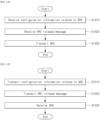
- a method performed by a user equipment (UE) in a wireless communication system comprises receiving, from a base station, configuration information related to a sounding reference signal (SRS), receiving an RRC release message from the base station, and transmitting, to the base station, the SRS in the RRC_INACTIVE state.
- SRS sounding reference signal
- the SRS may be related to a positioning.
- An RRC state of the UE may transit from an RRC_CONNECTED state to an RRC_INACTIVE state or an RRC_IDLE state based on the RRC release message.
- the RRC release message may include configuration information related to the SRS for positioning in the RRC_INACTIVE state.
- the SRS may be transmitted inside or outside an initial uplink (UL) bandwidth part (BWP).
- the transmission of the SRS may be dropped or performed in at least one symbol in which the collision occurs.
- Whether to perform the transmission of the SRS may be determined based on a priority between i) the SRS and ii) the other physical signal or the other physical channel, and the other physical channel may include a physical channel related to a small data transmission (SDT).
- SDT small data transmission
- the SDT may include a configured grant (CG)-SDT and/or a random access (RA)-SDT.
- CG configured grant
- RA random access
- the transmission of the SRS may be dropped in at least one symbol in which the collision occurs.
- the transmission of the SRS may be dropped in at least one symbol in which the collision occurs.
- the transmission of the SRS may be performed in at least one symbol in which the collision occurs.
- a physical channel related to the CG-SDT may be a physical uplink shared channel (PUSCH) transmitted based on a configured grant in the RRC_INACTIVE state.
- PUSCH physical uplink shared channel
- a physical channel related to the RA-SDT may be a physical uplink shared channel (PUSCH) transmitted based on a random access procedure in the RRC_INACTIVE state.
- PUSCH physical uplink shared channel
- the RRC release message may further include configuration information related to the SDT.
- the configuration information related to the SDT may include information related to a configured grant (CG)-SDT.
- the configuration information related to the SRS for positioning in the RRC_INACTIVE state may include information on at least one of i) an SRS resource and/or ii) a BWP. Based on information on the BWP, the SRS may be transmitted inside or outside the initial UL BWP.
- the method may further comprise transmitting, to the base station, the SRS in the RRC_CONNECTED state.
- the SRS may be transmitted inside an active UL BWP.
- the method may further comprise transmitting capability information to the base station.
- the capability information may be related to a support of the transmission of the SRS for positioning in the RRC_INACTIVE state.
- the capability information may include at least one of i) information representing whether the transmission of the SRS for positioning for the initial UL BWP in the RRC_INACTIVE state is supported and/or ii) information representing whether the transmission of the SRS for positioning outside the initial UL BWP in the RRC_INACTIVE state is supported.
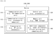
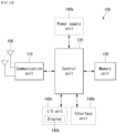
- a user equipment (UE) operating in a wireless communication system comprises one or more transceivers, one or more processors configured to control the one or more transceivers, and one or more memories operably connected to the one or more processors.
- the one or more memories store instructions for performing operations based on being executed by the one or more processors.
- the operations comprise receiving, from a base station, configuration information related to a sounding reference signal (SRS), receiving an RRC release message from the base station, and transmitting, to the base station, the SRS in the RRC_INACTIVE state.
- SRS sounding reference signal
- the SRS may be related to a positioning.
- An RRC state of the UE may transit from an RRC_CONNECTED state to an RRC_INACTIVE state or an RRC_IDLE state based on the RRC release message.
- the RRC release message may include configuration information related to the SRS for positioning in the RRC_INACTIVE state.
- the SRS may be transmitted inside or outside an initial uplink (UL) bandwidth part (BWP).
- the transmission of the SRS may be dropped or performed in at least one symbol in which the collision occurs.
- Whether to perform the transmission of the SRS may be determined based on a priority between i) the SRS and ii) the other physical signal or the other physical channel, and the other physical channel may include a physical channel related to a small data transmission (SDT).
- SDT small data transmission
- a device controlling a user equipment (UE) in a wireless communication system comprises one or more processors, and one or more memories operably connected to the one or more processors.
- the one or more memories store instructions for performing operations based on being executed by the one or more processors.
- the operations comprise receiving, from a base station, configuration information related to a sounding reference signal (SRS), receiving an RRC release message from the base station, and transmitting, to the base station, the SRS in the RRC_INACTIVE state.
- SRS sounding reference signal
- the SRS may be related to a positioning.
- An RRC state of the UE may transit from an RRC_CONNECTED state to an RRC_INACTIVE state or an RRC_IDLE state based on the RRC release message.
- the RRC release message may include configuration information related to the SRS for positioning in the RRC_INACTIVE state.
- the SRS may be transmitted inside or outside an initial uplink (UL) bandwidth part (BWP).
- the transmission of the SRS may be dropped or performed in at least one symbol in which the collision occurs.
- Whether to perform the transmission of the SRS may be determined based on a priority between i) the SRS and ii) the other physical signal or the other physical channel, and the other physical channel may include a physical channel related to a small data transmission (SDT).
- SDT small data transmission
- One or more non-transitory computer-readable medium stores one or more instructions.
- the one or more instructions perform operations based on being executed by the one or more processors.
- the operations comprise receiving, from a base station, configuration information related to a sounding reference signal (SRS), receiving an RRC release message from the base station, and transmitting, to the base station, the SRS in the RRC_INACTIVE state.
- SRS sounding reference signal
- the SRS may be related to a positioning.
- An RRC state of the UE may transit from an RRC_CONNECTED state to an RRC_INACTIVE state or an RRC_IDLE state based on the RRC release message.
- the RRC release message may include configuration information related to the SRS for positioning in the RRC_INACTIVE state.
- the SRS may be transmitted inside or outside an initial uplink (UL) bandwidth part (BWP).
- the transmission of the SRS may be dropped or performed in at least one symbol in which the collision occurs.
- Whether to perform the transmission of the SRS may be determined based on a priority between i) the SRS and ii) the other physical signal or the other physical channel, and the other physical channel may include a physical channel related to a small data transmission (SDT).
- SDT small data transmission
- a method performed by a base station in a wireless communication system comprises transmitting, to a user equipment (UE), configuration information related to a sounding reference signal (SRS), transmitting an RRC release message to the UE, and receiving the SRS from the UE of the RRC_INACTIVE state.
- UE user equipment
- SRS sounding reference signal
- the SRS may be related to a positioning.
- An RRC state of the UE may transit from an RRC_CONNECTED state to an RRC_INACTIVE state or an RRC_IDLE state based on the RRC release message.
- the RRC release message may include configuration information related to the SRS for positioning in the RRC_INACTIVE state.
- the SRS may be received inside or outside an initial uplink (UL) bandwidth part (BWP).
- UL initial uplink
- the transmission of the SRS may be dropped or performed in at least one symbol in which the collision occurs.
- Whether to perform the transmission of the SRS may be determined based on a priority between i) the SRS and ii) the other physical signal or the other physical channel, and the other physical channel may include a physical channel related to a small data transmission (SDT).
- SDT small data transmission
- a base station operating in a wireless communication system comprises one or more transceivers, one or more processors configured to control the one or more transceivers, and one or more memories operably connected to the one or more processors.
- the one or more memories store instructions for performing operations based on being executed by the one or more processors.
- the operations comprise transmitting, to a user equipment (UE), configuration information related to a sounding reference signal (SRS), transmitting an RRC release message to the UE, and receiving the SRS from the UE of the RRC_INACTIVE state.
- UE user equipment
- SRS sounding reference signal
- the transmission of the SRS may be dropped or performed in at least one symbol in which the collision occurs.
- Whether to perform the transmission of the SRS may be determined based on a priority between i) the SRS and ii) the other physical signal or the other physical channel, and the other physical channel may include a physical channel related to a small data transmission (SDT).
- SDT small data transmission
- the SRS transmission is performed or dropped based on a predefined priority. Therefore, ambiguity in terms of UE operation can be resolved. In addition, the reliability of uplink transmission performed in RRC_INACTIVE state can be improved.
- SRS sounding reference signal
- known structures or devices may be omitted or be shown in block diagrams while focusing on core features of each structure and device.
- downlink means communication from a base station to a terminal
- uplink means communication from the terminal to the base station.
- a transmitter may be part of the base station, and a receiver may be part of the terminal.
- the transmitter may be part of the terminal and the receiver may be part of the base station.
- the base station may be expressed as a first communication device and the terminal may be expressed as a second communication device.
- a base station may be replaced with terms including a fixed station, a Node B, an evolved-NodeB (eNB), a Next Generation NodeB (gNB), a base transceiver system (BTS), an access point (AP), a network (5G network), an AI system, a road side unit (RSU), a vehicle, a robot, an Unmanned Aerial Vehicle (UAV), an Augmented Reality (AR) device, a Virtual Reality (VR) device, and the like.
- the terminal may be fixed or mobile and may be replaced with terms including a User Equipment (UE), a Mobile Station (MS), a user terminal (UT), a Mobile Subscriber Station (MSS), a Subscriber Station (SS), an Advanced Mobile Station (AMS), a Wireless Terminal (WT), a Machine-Type Communication (MTC) device, a Machine-to-Machine (M2M) device, and a Device-to-Device (D2D) device, the vehicle, the robot, an AI module, the Unmanned Aerial Vehicle (UAV), the Augmented Reality (AR) device, the Virtual Reality (VR) device, and the like.
- UAV Unmanned Aerial Vehicle
- AR Augmented Reality
- VR Virtual Reality
- the following technology may be used in various wireless access systems, such as code division multiple access (CDMA), frequency division multiple access (FDMA), time division multiple access (TDMA), orthogonal frequency division multiple access (OFDMA), single carrier-FDMA (SC-FDMA), non-orthogonal multiple access (NOMA), and the like.
- CDMA may be implemented by radio technology such as universal terrestrial radio access (UTRA) or CDMA2000.
- UTRA universal terrestrial radio access
- TDMA may be implemented by radio technology such as global system for mobile communications (GSM)/general packet radio service (GPRS)/enhanced data rates for GSM evolution (EDGE).
- GSM global system for mobile communications
- GPRS general packet radio service
- EDGE enhanced data rates for GSM evolution
- the OFDMA may be implemented as radio technology such as IEEE 802.11 (Wi-Fi), IEEE 802.16 (WiMAX), IEEE 802-20, E-UTRA (evolved UTRA), and the like.
- the UTRA is a part of a universal mobile telecommunication system (UMTS).
- LTE-A evolution of 3GPP LTE.
- LTE means technology after 3GPP TS 36.xxx Release 8.
- LTE technology after 3GPP TS 36.xxx Release 10 is referred to as the LTE-A
- LTE technology after 3GPP TS 36.xxx Release 13 is referred to as the LTE-A pro.
- the 3GPP NR means technology after TS 38.xxx Release 15.
- the LTE/NR may be referred to as a 3GPP system.
- "xxx" means a standard document detail number.
- the LTENR may be collectively referred to as the 3GPP system. Matters disclosed in a standard document published before the present disclosure may refer to a background art, terms, abbreviations, etc., used for describing the present disclosure. For example, the following documents may be referenced.
- next-generation radio access technology considering enhanced mobile broadband communication (eMBB), massive MTC (mMTC), ultra-reliable and low latency communication (URLLC) is discussed, and in the present disclosure, the technology is called NR for convenience.
- eMBB enhanced mobile broadband communication
- mMTC massive MTC
- URLLC ultra-reliable and low latency communication
- NR is an expression representing an example of 5G radio access technology
- a New RAT system including NR uses an OFDM transmission scheme or a similar transmission scheme thereto.
- the new RAT system may follow OFDM parameters different from OFDM parameters of LTE.
- the new RAT system may follow numerology of conventional LTE/LTE-A as it is or have a larger system bandwidth (e.g., 100 MHz).
- one cell may support a plurality of numerologies. In other words, UEs that operate with different numerologies may coexist in one cell.
- the numerology corresponds to one subcarrier spacing in a frequency domain. By scaling a reference subcarrier spacing by an integer N, different numerologies may be defined.
- FIG. 1 illustrates an example overall NR system structure to which a method as proposed in the disclosure may apply.
- an NG-RAN is constituted of gNBs to provide a control plane (RRC) protocol end for user equipment (UE) and NG-RA user plane (new AS sublayer/PDCP/RLC/MAC/PHY).
- RRC control plane
- UE user equipment
- NG-RA user plane new AS sublayer/PDCP/RLC/MAC/PHY
- the gNBs are mutually connected via an Xn interface.
- the gNBs are connected to the NGC via the NG interface.
- the gNB connects to the access and mobility management function (AMF) via the N2 interface and connects to the user plane function (UPF) via the N3 interface.
- AMF access and mobility management function
- UPF user plane function
- the numerology may be defined by the subcarrier spacing and cyclic prefix (CP) overhead.
- CP cyclic prefix
- multiple subcarrier spacings may be derived by scaling the basic subcarrier spacing by integer N (or, ⁇ ).
- N integer
- the numerology used may be selected independently from the frequency band.
- various frame structures according to multiple numerologies may be supported.
- OFDM orthogonal frequency division multiplexing
- the multiple OFDM numerologies supported in the NR system may be defined as shown in Table 1.
- NR supports multiple numerologies (or subcarrier spacings (SCS)) for supporting various 5G services. For example, if SCS is 15 kHz, NR supports a wide area in typical cellular bands. If SCS is 30 kHz/60 kHz, NR supports a dense urban, lower latency and a wider carrier bandwidth. If SCS is 60 kHz or higher, NR supports a bandwidth greater than 24.25 GHz in order to overcome phase noise.
- numerologies or subcarrier spacings (SCS)
- An NR frequency band is defined as a frequency range of two types FR1 and FR2.
- the FR1 and the FR2 may be configured as in Table 1 below. Furthermore, the FR2 may mean a millimeter wave (mmW).
- mmW millimeter wave
- one set of frames for uplink and one set of frames for downlink may exist.
- FIG. 2 illustrates a relationship between an uplink frame and downlink frame in a wireless communication system to which a method described in the present disclosure is applicable.
- slots are numbered in ascending order of n s ⁇ ⁇ 0 , ... , N subframe slots , ⁇ ⁇ 1 in the subframe and in ascending order of n s ,f ⁇ ⁇ 0 , ... , N frame slots , ⁇ ⁇ 1 in the radio frame.
- One slot includes consecutive OFDM symbols of N symb ⁇ , and N symb ⁇ is determined according to the used numerology and slot configuration.
- the start of slot n s ⁇ is temporally aligned with the start of n s ⁇ N symb ⁇ .
- Not all UEs are able to transmit and receive at the same time, and this means that not all OFDM symbols in a downlink slot or an uplink slot are available to be used.
- Table 3 represents the number N symb slot of OFDM symbols per slot, the number N slot frame , ⁇ of slots per radio frame, and the number N slot subframe , ⁇ of slots per subframe in a normal CP.
- Table 4 represents the number of OFDM symbols per slot, the number of slots per radio frame, and the number of slots per subframe in an extended CP. [Table 3] ⁇ N symb slot N slot frame , ⁇ N slot subframe , ⁇ 2 12 40 4 [Table 4] ⁇ N symb slot N slot frame , ⁇ N slot subframe , ⁇ 0 14 10 1 1 14 20 2 2 14 40 4 3 14 80 8 4 14 160 16
- FIG. 3 illustrates an example of a frame structure in a NR system.
- FIG. 3 is merely for convenience of explanation and does not limit the scope of the present disclosure.
- a mini-slot may consist of 2, 4, or 7 symbols, or may consist of more symbols or less symbols.
- an antenna port In regard to physical resources in the NR system, an antenna port, a resource grid, a resource element, a resource block, a carrier part, etc. May be considered.
- the antenna port is defined so that a channel over which a symbol on an antenna port is conveyed may be inferred from a channel over which another symbol on the same antenna port is conveyed.
- the two antenna ports may be regarded as being in a quasi co-located or quasi co-location (QC/QCL) relation.
- the large-scale properties may include at least one of delay spread, Doppler spread, frequency shift, average received power, and received timing.
- FIG. 4 illustrates an example of a resource grid supported in a wireless communication system to which a method proposed in the present disclosure is applicable.
- a resource grid consists of N RB ⁇ N sc RB subcarriers on a frequency domain, each subframe consisting of 14 ⁇ 2 ⁇ OFDM symbols, but the present disclosure is not limited thereto.
- a transmitted signal is described by one or more resource grids, consisting of N RB ⁇ N sc RB subcarriers, and 2 ⁇ N symb ⁇ OFDM symbols, where N RB ⁇ ⁇ N RB max , ⁇ . N RB max , ⁇ denotes a maximum transmission bandwidth and may change not only between numerologies but also between uplink and downlink.
- one resource grid may be configured per numerology ⁇ and antenna port p.
- FIG. 5 illustrates examples of a resource grid per antenna port and numerology to which a method proposed in the present disclosure is applicable.
- the resource element ( k , l ) for the numerology ⁇ and the antenna port p corresponds to a complex value a k , l ⁇ p ⁇ .
- the indexes p and ⁇ may be dropped, and as a result, the complex value may be a k , l ⁇ p or a k , l ⁇ .
- Point A serves as a common reference point of a resource block grid and may be obtained as follows.
- the common resource blocks are numbered from 0 and upwards in the frequency domain for subcarrier spacing configuration ⁇ .
- n CRB ⁇ k N sc RB
- Physical resource blocks are defined within a bandwidth part (BWP) and are numbered from 0 to N BWP , i size ⁇ 1 , where i is No. Of the BWP.
- BWP bandwidth part
- n PRB in BWP i the common resource block
- n CRB n PRB + N BWP , i start
- N BWP , i start may be the common resource block where the BWP starts relative to the common resource block 0.
- FIG. 6 illustrates physical channels and general signal transmission used in a 3GPP system.
- the UE receives information from the eNB through Downlink (DL) and the UE transmits information from the eNB through Uplink (UL).
- the information which the eNB and the UE transmit and receive includes data and various control information and there are various physical channels according to a type/use of the information which the eNB and the UE transmit and receive.
- the UE When the UE is powered on or newly enters a cell, the UE performs an initial cell search operation such as synchronizing with the eNB (S601). To this end, the UE may receive a Primary Synchronization Signal (PSS) and a (Secondary Synchronization Signal (SSS) from the eNB and synchronize with the eNB and acquire information such as a cell ID or the like. Thereafter, the UE may receive a Physical Broadcast Channel (PBCH) from the eNB and acquire in-cell broadcast information. Meanwhile, the UE receives a Downlink Reference Signal (DL RS) in an initial cell search step to check a downlink channel status.
- PSS Primary Synchronization Signal
- SSS Secondary Synchronization Signal
- PBCH Physical Broadcast Channel
- DL RS Downlink Reference Signal
- a UE that completes the initial cell search receives a Physical Downlink Control Channel (PDCCH) and a Physical Downlink Control Channel (PDSCH) according to information loaded on the PDCCH to acquire more specific system information (S602).
- PDCCH Physical Downlink Control Channel
- PDSCH Physical Downlink Control Channel
- the UE may perform a Random Access Procedure (RACH) to the eNB (S603 to S606).
- RACH Random Access Procedure
- the UE may transmit a specific sequence to a preamble through a Physical Random Access Channel (PRACH) (S603 and S605) and receive a response message (Random Access Response (RAR) message) for the preamble through the PDCCH and a corresponding PDSCH.
- PRACH Physical Random Access Channel
- RAR Random Access Response
- a Contention Resolution Procedure may be additionally performed (S606).
- the UE that performs the above procedure may then perform PDCCH/PDSCH reception (S607) and Physical Uplink Shared Channel (PUSCH)/Physical Uplink Control Channel (PUCCH) transmission (S608) as a general uplink/downlink signal transmission procedure.
- the UE may receive Downlink Control Information (DCI) through the PDCCH.
- DCI Downlink Control Information
- the DCI may include control information such as resource allocation information for the UE and formats may be differently applied according to a use purpose.
- control information which the UE transmits to the eNB through the uplink or the UE receives from the eNB may include a downlink/uplink ACK/NACK signal, a Channel Quality Indicator (CQI), a Precoding Matrix Index (PMI), a Rank Indicator (RI), and the like.
- the UE may transmit the control information such as the CQI/PMI/RI, etc., through the PUSCH and/or PUCCH.
- the base station described in this disclosure may be a generic term for an object that transmits/receives data to and from UE.
- the base station described herein may be a concept including one or more transmission points (TPs), one or more transmission and reception points (TRPs), and the like.
- TPs transmission points
- TRPs transmission and reception points
- multiple TPs and/or multiple TRPs described herein may be included in one base station or included in multiple base stations.
- the TP and/or TRP may include a panel of a base station, a transmission and reception unit, and the like.
- the TRP described in this disclosure means an antenna array having one or more antenna elements available in a network located at a specific geographical location in a specific area.
- TRP transmission point
- the TRP may be replaced with a base station, a transmission point (TP), a cell (e.g., a macro cell/small cell/pico cell, etc.), an antenna array, or a panel and understood and applied as such.
- Positioning may mean determining the geographic location and / or speed of the UE by measuring a radio signal.
- the location information may be requested by a client (e.g. an application) related to the UE and reported to the client.
- the location information may be included in a core network or may be requested by a client connected to the core network.
- the location information may be reported in a standard format such as cell-based or geographic coordinates, and in this case, the estimation error values for the location(position) and speed of the UE and/or the positioning measurement method used for positioning may be reported together.
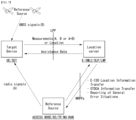
- FIG. 7 illustrates an example of a positioning protocol configuration for measuring a location of a user equipment (UE).
- UE user equipment
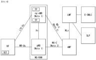
- FIG. 8 illustrates an example of architecture of a system for measuring a location of a UE.
- the AMF may receive a request for location service related to a specific target UE from another entity such as the GMLC (Gateway Mobile Location Center), or may decide to start the location service on behalf of the specific target UE in the AMF itself. Then, the AMF transmits a location service request to the LMF (Location Management Function).
- the LMF receiving the location service request may process the location service request and return a processing result including the estimated location of the UE to the AMF.
- the AMF may transmit the processing result received from the LMF to another entity.
- New generation evolved-NB (ng-eNB) and gNB may be network elements of NG-RAN that can provide measurement results for location tracking, and measure a radio signal for the target UE and transmit the result to the LMF.
- the ng-eNB may control some TPs (Transmission Points), such as remote radio heads, or PRS-only TPs supporting a PRS-based beacon system for E-UTRA.
- TPs Transmission Points
- the LMF may be connected to an Enhanced Serving Mobile Location Center (E-SMLC), and the E-SMLC may enable the LMF to access the E-UTRAN.
- E-SMLC may enable the LMF to support Observed Time Difference Of Arrival (OTDOA) which is one of the E-UTRAN positioning measurement methods, based on the downlink measurement which is obtained by the target UE through a signal transmitted from TPs dedicated for PRS in the eNB and/or E-UTRAN.
- OTDOA Observed Time Difference Of Arrival
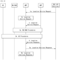
- FIG. 9 illustrates an example of a procedure for measuring a location of a UE.
- CM-IDLE Connection Management - IDLE
- the AMF may establish a signaling connection with the UE, and request a network trigger service to allocate a specific serving gNB or ng-eNB.
- This operation process is omitted in FIG. 9 . That is, in FIG. 8 , it may be assumed that the UE is in a connected mode. However, the signaling connection may be released during the positioning process by the NG-RAN for reasons such as signaling and data inactivity.
- a 5GC entity such as GMLC may request a location service for measuring the location of a target UE with a serving AMF.
- the serving AMF may determine that the location service is necessary for measuring the location of the target UE. For example, in order to measure the location of the UE for an emergency call, the serving AMF may decide to directly perform the location service.
- the AMF may send a location service request to the LMF, and based on step 3a, the LMF may initiate location procedures for obtaining location measurement data or location measurement assistance data together with the serving ng-eNB and the serving gNB.
- the LMF may request location-related information related to one or more UEs to the NG-RAN, and instruct the type of location information required and the associated QoS.
- the NG-RAN may transmit the location-related information to the LMF.
- the NG-RAN may transmit additional location-related information to the LMF through one or more NRPPa messages.
- 'location-related information' may mean all values used for location calculation, such as actual location estimation information and wireless measurement or location measurement, etc.
- the protocol used in step 3a may be an NRPPa protocol, which will be described later.
- the LMF may initiate location procedures for downlink positioning with the UE.
- the LMF may send location assistance data to the UE, or obtain a location estimate or location measurement.
- a capability transfer process may be performed.
- the LMF may request capability information from the UE, and the UE may transmit capability information to the LMF.
- the capability information may include information on a location measurement method that the LFM or UE can support, information on various aspects of a specific location measurement method, such as various types of assistance data for A-GNSS, and information on common characteristics that are not limited to any one location measurement method, such as the ability to handle multiple LPP transactions, etc.
- the UE may provide capability information to the LMF.
- a location assistance data transfer process may be performed in step 3b.
- the UE may request location assistance data from the LMF, and may indicate required specific location assistance data to the LMF.
- the LMF may deliver location assistance data corresponding thereto to the UE, and additionally, may transmit additional assistance data to the UE through one or more additional LPP messages.
- location assistance data transmitted from the LMF to the UE may be transmitted through a unicast method, and in some cases, the LMF may transmit location assistance data and/or additional assistance data to the UE without the UE requesting assistance data from the LMF.
- a location information transfer process may be performed in step 3b.
- the LMF may request the UE for location-related information related to the UE, and may indicate the type of location information required and the associated QoS. Then, in response to the request, the UE may transmit the location related information to the LMF. In this case, the UE may additionally transmit additional location-related information to the LMF through one or more LPP messages.
- 'location-related information' may mean all values used for location calculation, such as actual location estimation information and wireless measurement or location measurement, etc, and representatively, there may be a Reference Signal Time Difference (RSTD) value measured by the UE based on downlink reference signals transmitted from a plurality of NG-RAN and/or E-UTRAN to the UE. Similar to the above, the UE may transmit the location-related information to the LMF even if there is no request from the LMF.
- RSTD Reference Signal Time Difference
- step 3b is performed in the order of a capability transfer process, an assistance data transfer process, and a location information transfer process, but is not limited to this order.
- step 3b is not limited to a specific order in order to improve the flexibility of location measurement.
- the UE may request location assistance data at any time to perform the location measurement request already requested by the LMF.
- the LMF may also request location information, such as location measurements or location estimates, at any time.
- the UE may transmit capability information to the LMF at any time.
- an Error message may be transmitted/received, and an Abort message may be transmitted/received for stopping position measurement.
- the protocol used in step 3b may be an LPP protocol, which will be described later.
- step 3b may be additionally performed after step 3a is performed, or may be performed instead of step 3a.
- the LMF may provide a location service response to the AMF.
- the location service response may include information on whether the location estimation of the UE was successful and the location estimate of the UE.
- the AMF may deliver a location service response to a 5GC entity such as GMLC, and if the procedure of FIG. 9 is initiated by step 1b, the AMF may use a location service response to provide a location service related to an emergency call or the like.
- LTP LTE Positioning Protocol
- FIG. 10 illustrates an example of a protocol layer for supporting LPP message transmission.
- an LPP PDU may be transmitted through a NAS PDU between the MAF and the UE.
- the LPP may terminate a connection between a target device (e.g., UE in the control plane or SUPL Enabled Terminal (SET) in the user plane) and a location server (e.g. LMF in the control plane or SLP in the user plane).
- the LPP message may be delivered in the form of a transparent PDU through an intermediate network interface using an appropriate protocol such as NGAP through the NG-C interface, NAS/RRC through the LTE-Uu and NR-Uu interfaces.
- the LPP protocol enables positioning for NR and LTE based on various positioning methods.
- the target device and the location server may exchange capability information, assistance data for positioning, and/or location information with each other through the LPP protocol.
- error information exchange and/or an instruction to stop the LPP procedure may be performed through the LPP message.
- a signal transmission/reception operation based on the LPP protocol to which the method proposed in the present disclosure can be applied may be performed based on Table 5 below.
- Table 5 the protocol operates between a "target" and a "server".
- these entities are the UE and LMF respectively; in the SUPL context they are the SET and the SLP.
- a procedure may be initiated by either the target or the server.
- Capability Transfer Capabilities in an LPP context refer to the ability of a target or server to support different position methods defined for LPP, different aspects of a particular position method (e.g. different types of assistance data for A-GNSS) and common features not specific to only one position method (e.g. ability to handle multiple LPP transactions).
- LPP Capability Transfer procedure 1 The server may send a request for the LPP related capabilities of the target. 2. The target transfers its LPP-related capabilities to the server. The capabilities may refer to particular position methods or may be common to multiple position methods. LPP Capability Indication procedure is used for unsolicited capability transfer. 2) Assistance data Transfer Assistance data may be transferred either by request or unsolicited.
- assistance data delivery is supported only via unicast transport from server to target.
- Example of LPP Assistance Data Transfer procedure 1.
- the target may send a request to the server for assistance data and may indicate the particular assistance data needed.
- the server transfers assistance data to the target.
- the transferred assistance data should match any assistance data requested in step 1.
- the server may transfer additional assistance data to the target in one or more additional LPP messages.
- LPP Assistance Data Delivery procedure is used for unilateral assistance data transfer. This procedure is unidirectional; assistance data are always delivered from the server to the target.
- Location Information Transfer The term "location information" applies both to an actual position estimate and to values used in computing position (e.g., radio measurements or positioning measurements). It is delivered either in response to a request or unsolicited.
- Example of LPP Location Information Transfer procedure 1 The server may send a request for location information to the target, and may indicate the type of location information needed and associated QoS. 2. In response to step 1, the target transfers location information to the server. The location information transferred should match the location information requested in step 1. 3. Optionally (e.g., if requested in step 1), the target in step 2 may transfer additional location information to the server in one or more additional LPP messages.
- LPP Location Information Delivery procedure is used for unilateral location information transfer. Furthermore, the LPP Location Information Delivery procedure can only be piggybacked in the MO-LR request. 4) Multiple Transactions Multiple LPP transactions may be in progress simultaneously between the same target and server nodes, to improve flexibility and efficiency.
- no more than one LPP procedure between a particular pair of target and server nodes to obtain location information shall be in progress at any time for the same position method.
- the objective is to request location measurements from the target, and the server does not provide assistance data in advance, leaving the target to request any needed assistance data.
- Example of multiple LPP procedures 1.
- the server sends a request to the target for positioning measurements. 2.
- the target sends a request for particular assistance data. 3.
- the server returns the assistance data requested in step 2.
- the target obtains and returns the location information (e.g., positioning method measurements) requested in step 1. 5) Error handling
- the procedure is used to notify the sending endpoint by the receiving endpoint that the receiving LPP message is erroneous or unexpected.
- This procedure is bidirectional at the LPP level; either the target or the server may take the role of either endpoint in the corresponding procedure.
- Example of Error handling procedure 1. The target or server sends a LPP message to the other endpoint (i.e, "Server/Target"). 2. If the server or target ("Server/Target") detects that the receiving LPP message is erroneous or unexpected, the server or target transfers error indication information to the other endpoint ("Target/Server"). 6) Abort The procedure is used to notify the other endpoint by one endpoint to abort an ongoing procedure between the two endpoints. This procedure is bidirectional at the LPP level; either the target or the server may take the role of either endpoint in the corresponding procedure.
- Example of Abort procedure A LPP procedure is ongoing between target and server. 2. If the server or target (“Server/Target”) determines that the procedure must be aborted, and then the server or target sends an LPP Abort message to the other endpoint ("Target/Server”) carrying the transaction ID for the procedure.
- server/Target the server or target
- NRPPa NR Positioning Protocol A
- FIG. 11 illustrates an example of a protocol layer for supporting NRPPa transmission. Specifically, FIG. 11 illustrates a protocol layer for supporting transmission of an NRPPa PDU (NR Positioning Protocol a Protocol Data Unit).
- NRPPa PDU NR Positioning Protocol a Protocol Data Unit
- the NRPPa may be used for information exchange between the NG-RAN node and the LMF. Specifically, the NRPPa may be used to exchange E-CID for measurement transmitted from ng-eNB to LMF, data for supporting the OTDOA positioning method, Cell-ID and Cell location ID for the NR Cell ID positioning method, and the like.
- the AMF may route NRPPa PDUs based on the routing ID of the associated LMF through the NG-C interface even if there is no information on the associated NRPPa transaction.
- the procedure of the NRPPa protocol for location and data collection can be divided into two types.
- the first type is a UE associated procedure for delivering information on a specific UE (e.g., location measurement information, etc.)
- the second type is a non-UE associated procedure for delivering information applicable to an NG-RAN node and related TPs (e.g., gNB/ng-eNG/TP timing information, etc.).
- the two types of procedures may be supported independently or at the same time.
- a signal transmission/reception operation based on the NRPPa protocol to which the embodiments proposed in the present disclosure can be applied may be performed based on Table 6 below.
- Table 6 Positioning and data acquisition transactions between a LMF and NG-RAN node are modelled by using procedures of the NRPPa protocol.
- NRPPa procedures There are two types of NRPPa procedures: - UE associated procedure, i.e. transfer of information for a particular UE (e.g. positioning measurements); - Non UE associated procedure, i.e. transfer of information applicable to the NG-RAN node and associated TPs (e.g. gNB/ng-eNB/TP timing information).
- Parallel transactions between the same LMF and NG-RAN node are supported; i.e.
- a pair of LMF and NG-RAN node may have more than one instance of an NRPPa procedure in execution at the same time.
- the protocol is considered to operate between a generic "access node” (e.g. ng-eNB) and a “server” (e.g. LMF).
- a procedure is only initiated by the server.
- Example of a single NRPPa transaction 1. Access Node sends NRPPa Procedure Request to Server. 2. Server sends NRPPa Procedure Response to Acces Node. N. Access Node sends NRPPa Procedure Response (end transaction) to Server. (this step may be omitted).
- the exmaple shows a single NRPPa transaction. The transaction is terminated in step 2 in the case of a non UE associated procedure.
- LPPa transaction type may be "Location Information Transfer".
- location information applies both to an actual position estimate and to values used in computing position (e.g., radio measurements or positioning measurements). It is delivered in response to a request.
- the server sends a request for location related information to the NG-RAN node, and indicates the type of location information needed and associated QoS.
- the request may refer to a particular UE.
- the NG-RAN Node transfers location related information to the server.
- the location related information transferred should match the location related information requested in step 1.
- the NG-RAN node may transfer additional location related information to the server in one or more additional NRPPa messages when the positioning method is E-CID for E-UTRA.
- a message exchanged (transmitted and received) between a UE (a target device)/location server for positioning and a configuration related to the message may be based on Table 7 below.
- the positioning measurement methods supported by NG-RAN may include GNSS, OTDOA, E-CID (enhanced cell ID), Multi RTT (round trip time)/Multi-cell RTT, barometric pressure sensor positioning, WLAN positioning, Bluetooth positioning, and TBS (terrestrial beacon system), UTDOA (Uplink Time Difference of Arrival), etc.
- GNSS Global System for Mobile Communications
- OTDOA enhanced cell ID
- E-CID enhanced cell ID
- Multi RTT round trip time
- Multi-cell RTT barometric pressure sensor positioning
- WLAN positioning Bluetooth positioning
- TBS terrestrial beacon system
- UTDOA Uplink Time Difference of Arrival
- the reference RS can be an SRS configured by the higher layer parameter SRS-Resource or SRS-PosResource, CSI-RS, SS/PBCH block, or a DL PRS configured on a serving cell or a SS/PBCH block or a DL PRS configured on a non-serving cell. If the UE is configured for transmission of SRS-PosResource in RRC_INACTIVE mode, the configured spatialRelationInfoPos is also applicable. The UE is not expected to transmit multiple SRS resources with different spatial relations in the same OFDM symbol.
- the UE may use a fixed spatial domain transmission filter for transmissions of the SRS configured by the higher layer parameter SRS-PosResource across multiple SRS resources or it may use a different spatial domain transmission filter across multiple SRS resources.
- the UE In RRC_CONNECTED mode, the UE is only expected to transmit an SRS configured by the higher layer parameter SRS- PosResource within the active UL BWP of the UE.
- the UE can only be provided with a single RS source in spatialRelationInfoPos per SRS resource for positioning. For operation on the same carrier, if an SRS configured by the higher parameter SRS-PosResource collides with a scheduled PUSCH, the SRS is dropped in the symbols where the collision occurs.
- the sounding procedure may be triggered by the SRS request field included in DCI format 0_1.
- DCI format 0_1 A more specific DCI format configuration may be based on Table 9 below.
- ResourceSetForPositioning set to 'aperiodic' for a 2nd set of serving cells configured by higher layers 11 SRS resource set(s) configured with higher layer parameter aperiodicSRS-ResourceTrigger set to 3 or an entry in aperiodicSRS-ResourceTriggerList set to 3 SRS resource set(s) configured with higher layer parameter usage in SRS-ResourceSet set to 'antennaSwitching' and resourceType in SRS-ResourceSet set to 'aperiodic' for a 3rd set of serving cells configured by higher layers, or SRS resource set(s) configured by [SRS-ResourceSetForPositioning] and resourceType in [SRS-ResourceSetForPositioning] set to 'aperiodic' for a 3rd set of serving cells configured by higher layers, or SRS resource set(s) configured by [SRS-ResourceSetForPositioning] and resourceType in [SRS-ResourceSetForPositioning] set to
- PRS mapping may be based on Table 10 below.
- the MAC entity may be configured by RRC with SDT and the SDT procedure may be initiated by RRC layer.
- the SDT procedure can be performed either by Random Access procedure with 2-step RA type or 4-step RA type (i.e., RA-SDT) or by configured grant Type 1 (i.e., CG-SDT).
- RRC configures the following parameters for SDT procedure: - sdt-DataVolumeThreshold : data volume threshold for the UE to determine whether to perform SDT procedure; - sdt-RSRP-Threshold: RSRP threshold for UE to determine whether to perform SDT procedure; - cg-SDT RSRP-ThresholdSSB: an RSRP threshold configured for SSB selection for CG-SDT.
- Size of the CCCH message is not considered for data volume calculation 1> if the RSRP of the downlink pathloss reference is higher than sdt-RSRP-Threshold ; or 1> if sdt-RSRP-Threshold is not configured: 2> if the Serving Cell is configured with supplementary uplink as specified in TS 38.331 [5]; and 2> if the RSRP of the downlink pathloss reference is less than rsrp-ThresholdSSB-SUL : 3> select the SUL carrier. 2> else: 3> select the NUL carrier.
- the UE monitors PDCCH addressed to C-RNTI received in random access response until the RA-SDT procedure is terminated. If CG-SDT is selected above and after the initial transmission for CG-SDT is performed, the UE monitors PDCCH addressed to C-RNTI as stored in UE Inactive AS context as specified in TS 38.331 [5] and CS-RNTI until the CG-SDT procedure is terminated.
- Random Access Procedure RACH
- the UE may perform a random access procedure with respect to the base station.
- Random access procedures are used for a variety of purposes.
- the random access procedure may be triggered based on following events.
- the UE may acquire UL synchronization and UL transmission resources through a random access procedure.
- the random access procedure is divided into a contention-based random access procedure and a contention free random access procedure.
- the contention-based random access procedure is divided into a 4-step random access procedure (4-step RACH) and a 2-step random access procedure (2-step RACH).
- the UE may transmit a message (message 1, Msg1) including a preamble related to a specific sequence through a physical random access channel (PRACH), and receive a response message (Random Access Response (RAR) message) (message 2, Msg2) to the preamble through the PDCCH and the corresponding PDSCH.
- the UE may transmit a message (message 3, Msg3) including a Physical Uplink Shared Channel (PUSCH) by using the scheduling information in the RAR, and perform a collision (contention) resolution procedure such as reception of a physical downlink control channel signal and a corresponding physical downlink shared channel signal.
- the UE may receive a message (message 4, Msg4) including collision (contention) resolution information for a collision resolution procedure from the base station.
- the UE may transmit the UL transmission on the uplink shared channel as Msg3 of the random access procedure based on random access response information.
- Msg3 may include an RRC connection request and a UE identifier.
- the network may transmit Msg4, which may be treated as a contention resolution message on DL.
- Msg4 the UE may enter the RRC connected state.
- the UL grant in the RAR schedules PUSCH transmission to the base station.
- the PUSCH carrying the initial UL transmission by the UL grant in the RAR is also referred to as Msg3 PUSCH.
- Type-2 random access procedure (2-step RACH procedure), in which a (contention-based) random access procedure is performed in two steps, has been proposed to simplify the RACH procedure to achieve low signaling overhead and low latency.
- the operation of transmitting message 1 and the operation of transmitting message 3 in the 4-step RACH procedure may be performed as one operation in which the UE performs transmission of one message (message A) including PRACH and PUSCH in the 2-step RACH procedure, and the operation of transmitting message 2 and transmitting message 4 by the base station
- the 4-step RACH procedure may be performed as one operation in which the base station performs transmission of one message (message B) including the RAR and collision resolution information in the 2-step RACH procedure.
- a PUSCH transmission operation in RRC_INACTIVE state may be based on Table 13 below.
- a positioning measurement (or a procedure related to the positioning measurement) was supported only in the RRC connected state. Specifically, the entire procedure in which the UE receives PRS for the purpose of location measurement of the UE and reports an analysis of the received PRS to the base station/server was supported only in the RRC connected state. In addition, UL positioning measurement through SRS transmission was equally supported only in the RRC connected state.
- the PRS resource and/or the SRS resource may be configured not only inside an initial bandwidth part (BWP) but also outside the initial BWP for gain in terms of accuracy.
- the transmission of the PRS (and/or the transmission of the SRS) may be performed inside the initial BWP and/or outside the initial BWP.
- the initial BWP may mean an initial uplink (UL) BWP.
- the present disclosure sequentially describes a configuration method and a delivery method of a priority rule in consideration of a resource collision with other UL channels for SRS transmission in an RRC inactive state at a UE side.
- the terms ⁇ RRC inactive state' and ⁇ RRC connected state' related to an RRC state of the UE can be changed/interpreted/applied to 'RRC_INACTIVE mode' and ⁇ RRC_CONNECTED mode', respectively.
- the present disclosure is described focusing on an uplink channel, but it is not intended to limit the application of a priority rule according to embodiments of the present disclosure.
- the priority rule described below can be applied in relation to at least one of other downlink channels, other downlink physical signals, other uplink channels, and/or other uplink physical signals.
- an uplink channel e.g., PUSCH
- a downlink channel e.g., PDSCH
- the positioning measurement may be supported not only in RRC connected state but also in RRC inactive state.
- Information on SRS resources that the UE shall transmit when performing DL+UL positioning measurement such as UL or multi-RRT may be configured based on at least one of the following embodiments.
- the SRS resource in the RRC inactive state may be configured through a message releasing RRC connection (e.g., RRC Release message).
- a message releasing RRC connection e.g., RRC Release message
- the base station may configure the SRS resource in the RRC inactive state to the UE in a form of suspending resources pre-configured to the UE in the connected state through the RRC Release message.
- the RRC Release message may include configuration information (e.g., suspendConfig) for RRC_INACTIVE state.
- the suspendConfig may include configuration information related to the SRS for positioning in the RRC inactive state.
- the configuration information (e.g., SRS-PosRRC-InactiveConfig-r17) related to the SRS for positioning in the RRC inactive state may include i) a configuration (e.g., SRS-PosConfig-r17 ⁇ srs-PosResourceSetToAddModList-r17, srs-PosResourceToAddModList-r17) related to resources of the SRS and/or ii) a bandwidth part (BWP) configuration (e.g., bwp-NUL-r17 and/or bwp-SUL-r17).
- a carrier related to the BWP on which the SRS is transmitted may be a normal uplink carrier and/or a supplementary uplink carrier.
- the configuration related to the resources of the SRS may include information on at least one of SRS resources and/or a set of SRS resources.
- the RRC Release message may be based on Table 14below.
- a base station may transmit, to a UE, configuration information related to SRS for positioning in RRC inactive state via a physical channel used for data transmission to the UE in the RRC inactive state.
- the base station may transmit the configuration information to the UE via a physical channel related to Configured Grant-Small Data Transmission (CG-SDT) or Random Access-Small Data Transmission (RA-SDT).
- CG-SDT Configured Grant-Small Data Transmission
- R-SDT Random Access-Small Data Transmission
- the Small Data Transmission may refer to transmission/signaling of data performed through a radio bearers allowed in the RRC inactive state without a transition to RRC connected state.
- the UE may transmit the SRS to the base station in the RRC inactive state based on the configuration information.
- the SRS transmission in the RRC inactive state may be periodic and/or semi-persistent.
- a resource type of resources e.g., SRS-PosResource
- SRS-PosResource for the SRS transmission in the RRC inactive state may be configured with 'semi-persistent' or 'periodic'.
- the SRS resource may be configured/transmitted in up to 12 symbols (e.g., 1, 2, 4, 8 or 12 symbol(s)) within 1 slot.
- the expression 'the SRS resource is transmitted' in the present disclosure may mean ⁇ the SRS is transmitted based on the SRS resource' or 'the SRS is transmitted on the SRS resource'.
- An overlap configuration may be performed on UL channel (PRACH/msgA or msg3 as well as configured grant (CG)/random access (RA) based SDT) based on the configuration related to the SRS resource. Therefore, a priority configuration between the SRS transmitted for positioning in the RRC Inactive state and other channels is required.
- Information related to a method described below may be configured based on an RRC message or system information.
- information related to embodiments described below may be transmitted together in resource configuration for SRS for positioning.
- the RRC Release message may include information related to a priority described below.
- the information related to the priority described below may be pre-defined/pre-configured.
- the information related to the priority described below may be information defined/configured in UE/base station implementation.
- PRACH For PRACH, the following operation may be performed with respect to collision avoidance. Specifically, in a situation of single cell operation or Intra band CA, PRACH transmission is not performed in the same slot as SRS in order to prevent collision with other transmissions in advance (see Table 15 below).
- a UE does not transmit PRACH and PUSCH/PUCCH/SRS in a same slot or when a gap between the first or last symbol of a PRACH transmission in a first slot is separated by less than N symbols from the last or first symbol, respectively, of a PUSCH/PUCCH/SRS transmission in a second slot
- ⁇ is the SCS configuration for the active UL BWP.
- msg3 or msgA related to the RACH procedure has no restriction on SRS for positioning (i.e., transmission restriction in the same slot).
- the UE can transmit small data in the RRC inactive state without RRC connection from Rel-15 (Small Data Transmission in RRC inactive State).
- RACH based SDT and configured-grant based SDT are supported.
- the PUSCH data may also be transmitted within the initial BWP. Except for a PRACH preamble, a collision may occur between the SRS for positioning and the physical channel that may be transmitted in the RRC inactive state.
- a collision may occur between data channel (CG-SDT based PUSCH or RA-SDT based PUSCH), that may be transmitted from the UE to the base station in the RRC inactive state, and SRS for positioning in the RRC inactive state supported from Rel-17.
- data channel CG-SDT based PUSCH or RA-SDT based PUSCH
- SRS for positioning in the RRC inactive state supported from Rel-17.
- ACK information in the CG-SDT is transmitted to PUCCH in response to the base station, a collision may occur between the PUCCH and the SRS (for positioning) in the RRC inactive state.
- the collision may mean that two transmissions (e.g., SRS transmission and PUCCH/PUSCH transmission) overlap in a time domain.
- the collision may mean that at least one symbol for the SRS transmission overlaps with at least one symbol for the PUCCH transmission.
- the collision may mean that at least one symbol for the SRS transmission is the same as at least one symbol for the PUCCH transmission.
- only one of the two transmissions may be performed, and the other transmission may be dropped.
- an operation in which transmission is dropped due to the collision may be expressed as that the UE does not perform the corresponding transmission from a perspective of UE operation.
- the operation of the UE for collision handling (i.e., the operation that the UE performs one transmission and drops the other transmission in order to prevent the collision) may be performed only when carriers for the two transmissions are the same.
- the above operation is merely an example of the UE operation, and the operation of the UE for collision handling may be performed even when the carriers are not the same.
- the present disclosure describes a priority for a PUSCH transmitted by a UE and an SRS for positioning, and a rule of the priority may be configured as below.
- symbol '>' means that a variable on the left has a higher priority than a variable on the right.
- transmission of SRS for positioning has a priority for transmission of PUSCH for RACH. That is, in at least one symbol where a collision occurs, the transmission of SRS for positioning may be performed, and the transmission of PUSCH for RACH may be dropped.
- msg3 and msgA are determined at the UE side based on a selection of RACH type (e.g., Type 1 - 4-step RACH ⁇ msg3 or Type 2 ⁇ 2-step RACH ⁇ msgA). Therefore, since the overlapping is not expected in the time domain, msg3 and msgA are hereinafter referred to as ⁇ PUSCH for PRACH'.
- RACH type e.g., Type 1 - 4-step RACH ⁇ msg3 or Type 2 ⁇ 2-step RACH ⁇ msgA. Therefore, since the overlapping is not expected in the time domain, msg3 and msgA are hereinafter referred to as ⁇ PUSCH for PRACH'.
- the UE In CG-SDT and RA-SDT, the UE expects to preferentially select the CG- SDT, and when the associated PUSCH is not valid, the UE attempts the RA-SDT (i.e., the UE first performs the CG-SDT and performs the RA-SDT when the related resource/configuration is not valid).
- the PUSCH for CG-SDT and the PUSCH for RA-SDT are not expected to collide with each other, and thus are hereinafter referred to as ⁇ PUSCH for SDT'.
- ⁇ PUSCH for PRACH' may mean at least one of i) msg3 and/or ii) msgA
- ⁇ PUSCH for SDT' may mean at least one of i) PUSCH for CG-SDT and/or ii) PUSCH for RA-SDT.
- PUSCH used for RA based SDT is denoted as RA-SDT
- PUSCH used for CG-based SDT is denotes as CG-SDT.
- a rule defining SRS for positioning as the highest priority is defined.
- the rule according to the present embodiment considers the following technical matters.
- the UE For positioning measurement, the UE performs SRS for positioning transmission after a positioning related request is delivered from the LMF.
- SRS for positioning transmission
- a request for SRS transmission (for positioning) itself is determined as a request considering an emergency situation, etc., and the SRS for positioning is given the highest priority.
- the collision may occur in the CG-SDT.
- the rule i.e., Rule #1
- the rule since the UE can determine that the PUSCH for SDT(RA-SDT) is invalid, the UE may expect not to transmit a related preamble in a previous slot.
- the reason for this rule is as follows. In the case of CG-SDT, this is because the UE determines that the PUSCH resource is invalid when the collision occurs, and the UE may then attempt the RA-SDT in a duration in which the collision does not occur.
- SRS for positioning is given the highest priority for the same reason as the Rule # 1, but the CG-SDT is given a higher priority than PUSCH for RACH. That is, the present embodiment is a method of giving the importance of small data higher than that of RACH.
- the rule according to the present embodiment considers the following technical matters.
- SDT a state transition to RRC connected state is unnecessary because an amount of data to be transmitted is small, and thus PRACH transmission (e.g., preamble transmission) is unnecessary.
- the RA-SDT may be defined as having a priority over the PUSCH for RACH. In this instance, since the UE can determine that the PUSCH for SDT (RA-SDT) is invalid, the UE may expect not to transmit a related preamble in a previous slot.
- associated data (msg2, msgA PUSCH) is defined as the highest priority based on the priority of the PRACH.
- Other data (for SDT) is configured as a lower priority than the SRS for positioning due to the reason described in the Rule #1 ( ⁇ emergency situation').
- the SRS for positioning has a higher priority than the PUSCH for RA-SDT.
- the UE may determine that the resources (i.e., the resource for the PUSCH for RA-SDT) are invalid due to overlapping between the SRS for positioning and the PUSCH for RA-SDT.
- the UE may use a general preamble other than a preamble for the SDT when selecting the preamble. Since a plurality of SDTs can be configured, they may affect delay in the location measurement. Considering this, in the rule according to the present embodiment, the priority of the SRS for positioning is configured to be higher than the priority of data (i.e., PUSCH for SDT).
- the UE may prioritize the SRS for positioning transmission rather than the transmission of the SDT (i.e., in symbol(s) where the collision occurs, the UE may drop the SDT and perform the transmission of the SRS for positioning). Afterwards, the UE may transit to the RRC connected state and transmit data.
- the SRS may collide with the PUSCH for SDT. Hence, when the SRS is dropped, a delay for the SRS for positioning transmission may occur.
- the SRS for positioning is configured to be higher in priority than the PUSCH for SDT, and the SRS is not dropped when the collision occurs as in the above example. Therefore, the delay in the location measurement can be prevented.
- the UE may determine that the PUSCH resource where the collision occurs (e.g., the symbol(s) where the collision occurs) is invalid. Then, the UE may perform the RA-SDT. When a collision occurs between the RA-SDT and other transmissions, after that time point, the UE may retry the RA-SDT transmission based on a configured/indicated backoff indicator (BI).
- BI configured/indicated backoff indicator
- This rule is a method of giving a highest priority to PUSCH for RACH as in the reason described in the Rule #2.
- priorities of SRS for positioning and SDT are defined differently depending on a type of the SDT (i.e., CG-SDT or RA-SDT). Specifically, the CG-SDT is configured to be higher in priority than the SRS for positioning, and the RA-SDT is configured to be lower in priority than the SRS for positioning.
- the UE When small data transmission is needed, the UE expects to perform first the CG-SDT. Therefore, the UE may expect to perform the SDT through the CG- SDT as soon as possible and to perform the SRS transmission from remaining SRS resources for positioning before the deactivation for semi-persistent is delivered. In the case of RA-SDT, the UE may expect to attempt retransmission through the RA-SDT as indicated by BI.
- This rule is a method of giving a highest priority to PUSCH for RACH as in the reason described in the Rule #2 and varying a priority of SRS for positioning depending on a type of SDT.
- the UE may first perform CG-SDT. Since the UE only needs to perform RA-SDT in the event of failure of CG-SDT, the priority of the SRS for positioning is configured to be higher than the priority of CG- SDT in the present embodiment.
- the priority of the RA-SDT is configured to be higher than the priority of the SRS for positioning in the present embodiment. That is, if a collision occurs between the SRS for positioning and the CG-SDT, the UE may perform the SRS for positioning and not perform the CG- SDT. The UE may determine that the CG-SDT is invalid, and then perform RA-SDT.
- This rule is a method of giving a highest priority to small data transmission.
- the present embodiment considers a case where contents of small data to be transmitted are determined to be very important.
- the UE may operate as follows. 1) If the configured PUSCH resource is used for SDT(RA-SDT), the UE may suspend SRS transmission and select and transmit a preamble for SDT before the corresponding time point. 2) If a collision occurs between a PUSCH resource related to a RACH procedure and an SRS resource, the UE may perform SRS transmission, and may not transmit a preamble related to the RACH procedure (i.e., may not transmit a preamble and a PUSCH related to the RACH procedure).
- a priority of PUSCH transmission is defined to be higher than a priority of SRS for positioning.
- data transmission at the UE side may be considered to be more important than location measurement. For example, based on the data transmission at the UE side being determined to be more important than the location measurement, the priority rule according to the present embodiment may be applied.
- the UE may not perform SRS transmission in all the SRS resources for positioning (e.g., resources configured by SRS-PosResource) configured to overlap with other transmissions (PUSCH for RACH/PUSCH for SDT).
- the UE may perform transmission of the SRS for positioning in resources, where the collision does not occur, based on a capability.
- the resources where the collision does not occur may refer to resources (e.g., OFDM symbol(s)) in which other transmission is not scheduled. In this regard, specific examples are described.
- a priority of PUSCH transmission is defined to be higher than a priority of SRS for positioning.
- the priority rule according to the present embodiment prioritizes the SDT transmission over the PRACH for other purposes than the SDT. For example, if contents transmitted through the SDT consist of critical information, the priority rule according to the present embodiment may be applied.
- the UE may perform transmission of the SRS for positioning on resources, where a collision does not occur, based on a capability.
- priority rule may be defined based on a simple comparison between physical channels, not based on the purpose (RACH or SDT, etc.). That is, priority may be simply defined for collisions between PUSCH/PUCCH/SRS.
- the SRS for positioning may have the lowest priority.
- the PUCCH may refer to a PUCCH related to the SDT.
- the PUCCH may refer to a PUCCH related to feedback (ACKNACK) of the base station after performing the SDT. Since the PUCCH is a channel for data transmission and feedback (PUCCH) related to the data transmission, it may be determined that it is important to prioritize the data transmission over transmission of a reference signal. Considering this, the PUCCH may have a higher priority than the SRS for positioning. That is, the SRS for positioning may have a lower priority than all other UL channels if it is transmitted in an inactive state.
- transmission of the SRS for positioning is not performed in a partially overlapped portion, and transmission of the SRS for positioning may be performed in a portion where no collision occurs (e.g., non-overlapped symbol(s)).
- the UE may forward/transmit the capability to the base station or the LMF.
- a priority of the SRS for positioning may be higher than a priority of the PUCCH.
- the priority of the SRS for positioning may be lower than a priority of the PUSCH but higher than the priority of the PUCCH.
- the present embodiment takes the following technical matters into consideration.
- the PUCCH in the current RRC inactive state is transmitted for a response of the base station to data in the CG-SDT. That is, since the main purpose of the CG-SDT is data transmission of the UE, the response of the base station to the data may be less important than the data transmission.
- the SRS for positioning may be configured to be higher in priority than the PUCCH.
- a BW for the SRS for positioning transmission is configured to be large, including an initial BWP
- the UE may transmit the PUSCH in time/frequency resources colliding with PUSCH for SDT and/or RACH and expect the SRS for positioning transmission in the remaining resources. This is because performance for location measurement may be poor in terms of performance, but dropping the remaining portion may be inefficient in terms of resource efficiency.
- a power prioritization rule may be applied between the SRS and the PUSCH which are FDMed (frequency division multiplexing).
- the transmit power for the SRS/PUSCH may be determined by the rule as follows. Based on a collision rule, the transmit power may be first allocated for the PUSCH within the allowable transmit power, and the remaining power may be used for the transmission of the SRS for positioning.
- the UE may not transmit related msgA preamble or msg1 (related RA-SDT).
- the rule(s) listed above have been described focusing on the SRS for positioning, but the rules can also be applied when performing general SDT. Specifically, even if the SRS for positioning is excluded, when the UE attempts CG-SDT, a collision between multiple PUSCH resources and PRACH or PUSCH associated with a normal PRACH procedure not the RA-SDT (e.g., a RACH procedure triggered by another event not the SDT) may occur. Accordingly, the priority rules described above may be applied for collision handling with other UL channels in the SDT.
- a preamble (e.g., PRACH) used for the RACH procedure in the above description may have the highest priority regardless of whether to perform the SDT.
- the PRACH preamble may have the highest priority regardless of whether the RACH procedure has been triggered for the SDT.
- a priority of the preamble for RA-SDT may be configured to be the same as a priority of the RA-SDT.
- the CG-SDT may include a PUCCH for CG-SDT.
- the CG-SDT and the PUCCH have an equivalent relationship, unless otherwise stated. That is, the PUCCH for CG-SDT may follow the priority rule described above. This is because, in the case of PUCCH transmitted in the RRC inactive state, the PUCCH is transmitted only for the current CG-SDT.
- the priority of the SRS for positioning may be lower than the priority of the PUSCH, but higher than the priority of the priority of the PUCCH.
- the reason for this is as follows. This is because the PUCCH is a resource used for a response of the CG-SDT, and even if no response is given, the UE using the CG- SDT expects to try again RA-SDT or CG-SDT in the future.
- a capability related to the above-described priority rule may be defined/reported. That is, the UE may transmit capability information related to the above-described priority rule (and/or SRS for positioning in RRC INACTIVE state (mode)) to the base station.
- the capability may be based on at least one of the following examples.
- the capability may be related to whether to support the SRS for positioning in the RRC INACTIVE state (mode).
- the UE may transmit, to the base station, capability information including information representing whether to support the SRS for positioning in the RRC INACTIVE state (mode).
- the capability information may include 1) information (e.g., srs-PosResourcesRRC-Inactive-r17) representing whether positioning SRS transmission in the RRC INACTIVE state (mode) for an initial UL BWP is supported and/or 2) information (e.g., posSRS-RRC-Inactive-OutsideInitialUL-BWP-r17) representing whether positioning SRS transmission outside the initial UL BWP in the RRC INACTIVE state (mode) is supported.
- information e.g., srs-PosResourcesRRC-Inactive-r17
- posSRS-RRC-Inactive-OutsideInitialUL-BWP-r17 representing whether positioning SRS transmission outside the initial UL BWP in the RRC INACTIVE state (mode) is supported.
- the capability information according to the present embodiment may be based on Table 16 below.
- Table 16 srs-PosResourcesRRC-Inactive-r17 Indicates support of positioning SRS transmission in RRC_INACTIVE for initial UL BWP.
- the capability signalling comprises the following parameters: - maxNumberSRS-PosResourceSetPerBWP-r17 Indicates the max number of SRS Resource Sets for positioning supported by UE; - maxNumberSRS-PosResourcesPerBWP-r17 indicates the max number of P/SP SRS Resources for positioning; - maxNumberSRS-ResourcesPerBWP-PerSlot-r17 indicates the max number of P/SP SRS Resources for positioning per slot; - maxNumberPeriodicSRS-PosResourcesPerBWP-r17 indicates the max number of periodic SRS Resources for positioning; - maxNumberPeriodicSRS-PosResourcesPerBWP-PerSlot-r17 indicates the max number of periodic SRS Resources for positioning per slot.
- the capability signalling comprises the following parameters: - maxSRSposBandwidthForEachSCS-withinCC-FRI-r17 Indicates the maximum SRS bandwidth supported for each SCS that UE supports within a single CC for FR1; - maxSRSposBandwidthForEachSCS-withinCC-FR2-r17 indicates the maximum SRS bandwidth supported for each SCS that UE supports within a single CC for FR2; - maxNumOfSRSposResourceSets-r17 indicates the max number of SRS Resource Sets for positioning supported by UE; - maxNumOfPeriodicSRSposResources-r17 indicates the max number of periodic SRS Resources for positioning; - maxNumOfPeriodicSRSposResourcesPerSlot-r17 indicates the max number of periodic SRS Resources for positioning per slot; - differentNumerologyBetweenSRSposAndInitialBWP-r17 indicates the support of different numerology between the SRS and the initial UL
- the UE can include this field only if the UE supports srs-PosResourcesRRC-Inactive-r17 . Otherwise, the UE does not include this field;
- the SRS should have a locationAndBandwidth, SCS, CP, defined the same way as a legacy BWP.
- NOTE 2 If differentCenterFreqBetweenSRSposAndInitialBWP-r17 is not signalled, the UE only supports same center frequency between the SRS for positioning and initial UL BWP.
- NOTE 3 If differentNumerologyBetweenSRSposAndInitialBWP-r17 is not signalled, the UE only supports same numerology between the SRS and the initial UL BWP.
- maxSRSposBandwidthForEachSCS-withinCC-FRI-r17 and maxSRSposBandwidthForEachSCS-withinCC-FR2-r17 and the fields of maxNumOfSRSposResourceSets-r17, maxNumOfPeriodicSRSposResources-r17, maxNumOfPeriodicSRSposResourcesPerSlot-r17, maxNumOfPeriodicAndSemipersistentSRSposResources-r17, maxNumOfPeriodicAndSemipersistentSRSposResourcesPerSlot-r17, and switchingTimeSRS-TX-OtherTX-r17 shall be reported together if supported by UE.
- srsPosWithoutRestrictionOnBWP-r17 is not applicable to FDD or SUL bands.
- the capability may relate to a unit that applies a priority.
- the capability information may include information representing whether the above-described priority rule for at least one of a symbol, a slot, or a subframe is supported by the UE. If multiple units (e.g., symbols and slots) are supported at the same time, the UE may report whether the multiple units can be supported.
- the base station or the LMF may indicate/configure a unit for applying the priority rule based on the capability information.
- Configuration information based on the capability may be transmitted via LPP, RRC or MAC. For example, the base station may transmit the configuration information based on the capability to the UE based on at least one of an LPP message, an RRC message, or MAC CE.
- the priority rule may be defined/represented as bitwise information.
- the bitwise information may be one-to-one mapping of bits (or bit values) and the priority rules.
- the priority may be flexibly changed as the base station or the LMF configures the bitwise information to the UE.
- the bitwise information may represent specific priority rules selected from among the above-described priority rules (Rule #1 to Rule #3-1) in the form of bitwise. If '3 bits' are allocated to all bits for priority, the three bits may be sequentially associated with the Rules #1, #3 and #5 from the lowest bit (e.g., the Rule #1 is '001', the Rule #3 is '010', and the Rule #5 is '100'), respectively.
- the base station or the LMF may set ('ON') only one bit of the 3 bits to '1' and transmit it to the UE.
- the bitwise information may be transmitted directly to the UE from the LMF via LPP.
- information related to the bitwise information may be transmitted to the base station from the LMF via LPPa.
- the base station may indicate/configure information related to the priority rules (based on the bitwise information) to the UE via RRC/MAC.
- the UE may transmit corresponding support information (i.e., information related to the capability) to the LMF.
- the base station or the LMF may configure a window, in which the priority rule is valid, to the UE via LPP/RRC/MAC. That is, the UE may apply the above-described priority rule in a duration indicated/configured by the base station/LMF.
- a remaining duration (a duration other than the indicated/configured duration) may be given a priority by implementation of the UE or may follow a single priority (e.g., default priority) according to the rule.
- a start (or start point) of the duration may be based on a start/end point of a channel regularly monitored by the UE, such as an SSB or a paging occasion.
- the window may be as much as a defined duration starting from a start point based on the start/end point of the channel. In other words, the window may end when time as much as the duration defined above elapses from the corresponding start point. Further, the window may have a periodicity.
- a start point of the window may be time at which the UE receives a request for the SRS for positioning transmission, or a start point of the most contiguous SRS for positioning.
- capability reporting may be performed for each UE as to whether the priority is supported/applied in units of symbol, slot, or subframe. Specifically, the UE may report, to the LMF or the base station, whether the priority determined within the window is supported per unit.
- the above-described priority rules have been described focusing on the SRS for positioning in the RRC inactive state, the above-described priority rules can also be applied to SRSs for other purposes.
- a normal SRS used for beam management, channel estimation, or antenna switching may be transmitted in the RRC inactive state.
- the normal SRS may follow the above-described priority rules.
- the normal SRS may refer to an SRS configured with a usage according to other purposes, not for positioning. The usage may be configured with one of beamManagement, codebook, nonCodebook or antennaSwitching.
- the normal SRS and the SRS for positioning are transmitted within a single CC, the normal SRS may have a lower priority than the SRS for positioning.
- the rule may be applied to other UL RSs in the RRC inactive state.
- Observation #2 • The SRS for positioning can collide with the following UL channels in the RRC Inactive state: ⁇ PUSCH (in both SDT and RACH procedures(except for RA-SDT)) ⁇ PUCCH (in CG-SDT procedure)
- Proposal #2 • RAN1 should discuss/define a priority rule between SRS for positioning and other UL channels (e.g., PUSCH and PUCCH).
- An embodiment (e.g., Rule #2) in which the SRS for positioning has a higher priority than the SDT (e.g., at least one of RA-SDT and/or CG-SDT) as described above may be based on an observation and a proposal according to Table 19 below.
- Table 19 Observation #3: • Except for RA-SDT, PUSCH in the common RACH procedure needs to have higher priority than SRS for positioning since the common RACH procedure is the one of the major procedure in the RRC inactive state and it is used for many purposes. But for SDT, at least we think that RAN1 should consider the issue from the efficiency of view and also need to figure out carefully which has more critical impact between SRS for positioning and PUSCH/PUCCH for SDT.
- multiple resources can be configured and then the resources might be reserved until the UE is ready to transmit small data.
- SRS for positioning has lower priority than PUSCH/PUCCH for SDT and the resource are overlapped, not only do resources for PUSCH/PUCCH can be abandoned even UE does not ready for transmission of SDT, latency for positioning measurement would increase.
- the UE spontaneously regards the PUSCH for SDT as invalid and then the small data can be naturally transmitted through RA-SDT procedure.
- RA-SDT even though UE also fails to attempt transmission of SDT when SRS for positioning has high priority and the resource are overlapped, UE can repeat it several times in accordance with back-off indicator.
- RAN1 should at least adopt that SRS for positioning has higher priority than PUSCH/PUCCH for SDT.
- ⁇ Latency is not a crucial factor for SDT if the data transfer is transmitted properly without change of RRC state.
- Proposal #3 • For priority rule between SRS for positioning and other UL channels (e.g. PUSCH and PUCCH), RAN1 should adopt following rules: ⁇ SRS for positioning has higher priority than PUSCH/PUCCH for SDT ⁇ SRS for positioning has lower priority than other UL channel (except for PUSCH/PUCCH for SDT)
- priorities of other channels with respect to SRS for positioning of a UE need to be defined based on the above-described embodiments (e.g., at least one of the Rule #1, the Rule #1-1, the Rule #2, the Rule #2-1, the Rule #2-2, the Rule #2-3, the Rule #3, or the Rule #3-1).
- a method of configuring/indicating the priorities is described below.
- channels and related procedures required for the delivery of information related to the priorities may vary.
- an SRS for positioning is denoted as ⁇ SRSp' so as to be distinguished from an SRS ( ⁇ SRSn') configured/transmitted for usage of beam management, antenna switching, etc.
- ⁇ SRSp' an SRS for positioning
- ⁇ SRSn' an SRS configured/transmitted for usage of beam management, antenna switching, etc.
- the expressions 'SRSp' and ⁇ SRSn' are merely for ease of description and distinction, and are not intended to limit the technical idea of embodiments described below to the above expression. That is, the SRSp may refer to the SRS for positioning, and the SRSn may refer to an SRS configured with a usage for purposes other than positioning.
- the usage may be one of beamManagement, codebook, nonCodebook, or antennaSwitching.
- Information on a priority described below may be divided into a plurality of options to cover multiple use cases.
- Each option may include a plurality of states.
- a priority may be configured by each state.
- the state for each option may be defined in the regulations.
- the LMF or the base station may directly or indirectly indicate/configure priority information for the options and the states to the UE based on scenarios # 1/#2 described below.
- the LMF may directly indicate/configure information related to the above-described priority rules to the UE based on A of the scenario # 1 described below.
- the LMF may indirectly indicate/configure information related to the above-described priority rules to the UE based on B (i ⁇ iv) of the scenario #1 described below (i.e., LMF ⁇ base station ⁇ UE).
- the base station may indicate/configure information related to the above-described priority rules to the UE based on at least one of A to D of the scenario #2 described below.
- priority information may include three options for a priority of the SRSp. And/or, options 1/2/3 may have 2/3/2 states, respectively.
- the SRSp may have a highest priority based on the option # 1.
- the SRSp may have a lower priority than a preamble based on the option #2.
- the SRSp may have a lowest priority based on the option#3.
- Priorities of the SRSp, PUSCH, and PUCCH may be divided into high and low priorities based on two states of the option #1 .
- the SRSp may have a higher priority than the PUSCH/PUCCH based on a first state of the option #1 .
- the SRSp may have a lower priority than the PUSCH/PUCCH based on a second state of the option #1.
- priorities based on the option #2 may be subdivided based on three states of the option #2.
- a priority between the SRSp and other UL channels may be defined based on the three states of the option #2.
- the priority rules may be defined based on a plurality of options without distinction of the above-described states.
- the base station or the LMF may transmit priority information including a single value or a plurality of values for each of the following scenarios to the UE in indicating/configuring the priorities according to the regulations.
- each of the plurality of values may be a value assigned to indicate an option and configure/indicate priorities based on states belonging to the option.
- Priority information i.e., information related to the priority rules
- the priority information may be transmitted from the LMF and/or the base station to the UE via different physical channels or signaling based on the following scenarios.
- This scenario is a method in which the LMF selects priority information and transmits it to the UE.
- the LMF may not recognize RRC state of the UE.
- each base station may inform the LMF of whether a state transition for the RRC state of the UE is performed, via NRPPa message.
- the LMF even if the LMF sends the priority information to the UE, it may not be necessary for the UE to inform the base station of the priority information received from the LMF.
- the reason for this operation is as follows.
- the UE may not transmit the priority information to the base station in that the positioning is directly calculated/managed by the LMF.
- the LMF may send a priority (priority information) to the UE and at the same time send the priority information to the base station. Therefore, the UE may not transmit the priority information to the base station in order to reduce unnecessary signaling.
- the reason why the priority information is also transmitted to the base station is that it may be necessary to configure a resource such as a preamble occasion or an SDT in the base station.
- the corresponding information (information related to the priority rules) may be added to an existing specific NRPPa message, or an additional NRPPA message and a related procedure may be additionally defined.
- This method is a method in which the LMF directly transmits a priority to the UE.
- the gNB directly transmits/configurates it to the UE. Therefore, information on a priority of the SRSp may be transmitted through an existing LPP message to support the corresponding method.
- priority information for the SRSp may be transmitted together in addition to existing provided information through assistance information that delivers the configuration of the existing DL PRS resource. The information may also be transmitted via physical channel/signal described in the scenario #2.
- the LMF may include information on a preferred priority within the NRPPa message below in the base station and transmit the information to the base station. Finally, the determination of the priority may be performed by the base station. The base station may transmit information on the determined priority to the UE via the physical channel/signal described in the scenario #2.
- the LMF may send a message including information related to an SRS resource set/SRS resource to the base station.
- the SRS resource set/SRS resource may be an SRS resource set or an SRS resource for which triggering is required when the base station requests the UE to transmit semi-persistent (SP)/aperiodic (A) SRS.
- SP semi-persistent
- A aperiodic
- the SP/P SRSp may be supported in the RRC inactive state.
- the LMF may add priority information for the SRSp to the existing activation request/deactivation message and transmit it to the base station.
- the UE may operate on the assumption that the indicated/associated priority has expired or is invalid.
- the original purpose of the corresponding message is for the LMF to transmit resource information (e.g., resource type/# of periodic transmission, BW/SRS resource set, etc.) that would like to be further considered when the LMF configures the SRS resource to the base station.
- resource information e.g., resource type/# of periodic transmission, BW/SRS resource set, etc.
- This message (positioning information request) is a common message that is not related to a type (P/SP/A) of the SRSp. Therefore, if a priority of the SRSp does not depend on the type, the LMF may indirectly provide preferred priority information to the base station through the message.
- the base station may transmit the priority information received from the LMF to the UE.
- This message is a message transmitted when the LMF indicates a measurement report from the base station.
- the LMF may transmit together priority information within the message.
- the base station may perform an update of SRS resource on the UE based on the received priority information.
- the update of the SRS resource may be performed via RRC or system information. If the priority information is transmitted via the system information, an update of the system information may also be required.
- the LMF transmits a message (assistance information control) to the base station for assistance information broadcasting.
- the message includes assistance data related to DL PRS (related with posSIB) to be broadcasted by the base station.
- assistance data related to DL PRS (related with posSIB) to be broadcasted by the base station.
- the present embodiment may be applied based on determining that there is little change in a priority related to the SRSp.
- the base station may update the priority based on the information obtained through the message when the SRS resources are configured and may transmit the priority to the UE.
- the base station may transmit the priority information received from the LMF to the UE via system information/RRC/MAC.
- the scenario #2 is a case in which it is considered that the base station configures its own priority regardless of whether or not there is configuration/indication of the LMF and indicates/configures the priority to the UE. If the base station directly configures the priority, the priority information does not need to be additionally transmitted to the LMF, and a physical channel on which the priority information is transmitted may vary depending on the RRC state of the UE.
- the base station may indicate the priority information via RRC/system information/MAC-CE.
- the base station may directly indicate priority information related to the SRSp of the RRC inactive state in the RRC connected state of the UE, and the UE may apply the indicated/configured priority information in the RRC Inactive state.
- the base station may configure it to the UE in the RRC inactive state via a physical channel described below.
- the base station may directly indicate the priority information in the RRC inactive state to the UE through an RRC connection release message (e.g., RRC release message).
- RRC connection release message e.g., RRC release message
- the UE may transmit the SRSp in the RRC inactive state based on the priority information.
- Physical channels used by the base station to transmit priority information for the SRSp to the UE are described in detail below. Based on the physical channels described below, a single or a plurality of bit information as described above may be transmitted from the base station to the UE via each channel. All information may be sent to each single channel (e.g., PDCCH or PDSCH) required for each procedure. Alternatively, each information may be split and transmitted through a plurality of channels (e.g., PDCCH and PDSCH).
- priority information for the SRSp may be transmitted along with a response to the UL SDT.
- the base station may send a response to the data and additional information to the UE via the PDCCH and the PDSCH.
- the base station may transmit together priority information on the SRSp to the UE in addition to response information on the basic UL-SDT.
- the UE may prioritize the SRSp configured after the time of receiving the priority information to transmit the SRSp. This method may be constrained because the base station can transmit the information after the UE triggers the UL-SDT.
- priority information for the SRSp may be transmitted through the DL SDT.
- the base station may transmit not only data information but also resource information related to the SRSp or priority information related to the SRSp to the UE by using the DL-SDT.
- the base station may transmit priority information based on PDCCH and/or PDSCH for the DL-SDT.
- the present embodiment may be applied when the base station determines that SRSp transmission of the UE has the high priority.
- priority information for the SRSp may be transmitted through a paging procedure.
- the priority information may be transmitted through RAN paging triggering.
- the priority information for the SRSp may be transmitted together via system information.
- the base station may operate as follows.
- the base station may 'on' modification information for system information triggering the RAN paging to the UE based on the change of the system information.
- the base station sends a paging message to the UE to inform the UE of the change of the system information.
- the UE receiving the paging message may receive new system information (system information including the changed priority information) from the base station in a modification period.
- the base station may separately send the priority information to the UE through reserved bits of DCI.
- the base station may add the priority information to record information (e.g., a paging record list) and transmit the same to the UEs.
- the record information may be transmitted based on a PDSCH.
- the record information may sequentially include priority information for each UE. For example, after M records for M UEs in the record information, N bits may be additionally allocated for priority configuration information.
- the record information may include priority configuration information for each of the M UEs (e.g., the priority configuration information for each UE is N/M bit).
- priority information for the SRSp may be transmitted through a RACH procedure.
- the base station may send information on the SRSp to the UE together based on the existing msg2/4B message. And/or, the base station may send the priority information to the UE on a PDSCH related to the RACH procedure as well as a PDCCH associated with the PDSCH.
- the information transmission for priority described above may be used for indication of some priorities not only in the RRC inactive state but also in the RRC connected state.
- the above-described priority i.e., priority rule
- the indicated/configured priority may be deactivated.
- the base station or the LMF separately indicates and configures the priority for the SRSp of the RRC inactive state in the RRC connected state or the RRC inactive state.
- the UE may follow the priority only in the RRC inactive state, and then release the indicated/configured priority and follow a default priority in the RRC connected state.
- the UE may operate by prioritizing priority information received from the base station. That is, it may be assumed that the UE receives priority configuration information from the LMF, and then additionally receives priority configuration information from the base station. The UE may operate based on a priority according to the indication/configuration of the base station. Conversely, it may be assumed that priority configuration by the base station is first performed and additional indication/configuration from the LMF is performed. The UE may follow the priority indication/configuration of the base station as it is, and may report details (or reasons) of failure to the LMF through a response message.
- the above-described priority may be a priority between some UL channels and the SRSp, not a priority between all UL channels, that can be transmitted by the UE, and the SRSp.
- the some UL channels may be UL channels determined considering a case where positioning accuracy at the UE side needs to be ensured or a case where data transmission is instantaneously determined to be more important than a configurated priority.
- the UE may send preferred priority information to the base station or the LMF. The information may be sent via PUCCH, PUSCH, etc., used in the UL-SDT or paging or RACH procedure.
- the above-described priority may be configured based on an SRS type (e.g., periodic (P)/semi-persistent (SP)/aperiodic (A)).
- SRS type e.g., periodic (P)/semi-persistent (SP)/aperiodic (A)
- P periodic
- SP sub-persistent
- A aperiodic
- the above-described priority may be applied to all the SRS types based on one common priority information.
- the UE may send to the LMF whether to support the above-described priority together when sending a capability to the LMF, and the LMF may send information on the capability to the base station.
- Whether to support the priority may mean whether the UE supports the above-described priority rules when transmitting the SRSp in the RRC inactive state.
- the information transmission method for the priority may be utilized to transmit information on a priority of PRS as well as the SRSp.
- the PRS is a part of accuracy enhancement of the RRC inactive state, and a priority of the PRS with respect to other DL channels (e.g., SSB, PDCCH, PDSCH, etc.) may be stipulated per the above-described option and/or state.
- the SRS for positioning may be changed/replaced with the PRS and applied.
- the LMF may directly select priority information of the PRS and provide it to the UE.
- the LMF may transmit the priority information to the UE and at the same time transmit it to the base station through the NRPPa message.
- a rule may be defined so that a base station informs a UE of information about whether to apply the proposed methods (or information on rules of the proposed methods) via pre-defined signaling (e.g., physical layer signaling or higher layer signaling).
- operations e.g., operations related to the SRS for positioning
- a device e.g., processors 102 and 202 of FIG. 17
- FIGS. 16 to 20 operations related to the SRS for positioning
- the operations (e.g., operations related to the SRS for positioning) of the UE/base station/location server according to the above-described embodiments can be stored in a memory (e.g., memories 104 and 204 of FIG. 17 ) in the form of commands/programs (e.g., instructions, executable codes) for running at least one processor (e.g., processors 102 and 202 of FIG. 17 ).
- a memory e.g., memories 104 and 204 of FIG. 17
- commands/programs e.g., instructions, executable codes
- FIG. 12 illustrates operations of a UE, TRP, and LMF to which a method proposed in the present disclosure can be applied.
- the location server and/or the LMF may transmit configuration information to the UE, and the UE may receive it.
- the location server and/or the LMF may transmit reference configuration information to a transmission and reception point (TRP), and the TRP may receive it.
- TRP transmission and reception point
- the TRP may transmit reference configuration information to the UE, and the UE may receive it.
- the operation 2001 according to the exemplary embodiment may be omitted.
- the operations 2001 according to an exemplary embodiment and the operations 2003 and 2005 according to an exemplary embodiment may be optional.
- the TRP may transmit a signal related to configuration information to the UE, and the UE may receive it.
- the signal related to the configuration information may be a signal for positioning of the UE.
- the UE may transmit a signal related to positioning to the TRP, and the TRP may receive it.
- the TRP may transmit the signal related to positioning to the location server and/or the LMF, and the location server and/or the LMF may receive it.
- the UE may transmit the signal related to positioning to the location server and/or the LMF, and the location server and/or the LMF may receive it.
- operations 2009 and 2011 according to the exemplary embodiment may be omitted.
- operation 2013 according to an exemplary embodiment may be omitted.
- operations 2009 and 2011 according to the exemplary embodiment may be performed.
- operations 2009 and 2011 according to an exemplary embodiment and operations 2013 according to an exemplary embodiment may be optional.
- the signal related to positioning may be obtained based on the configuration information and/or the signal related to the configuration information.
- FIG. 13 is a flowchart for explaining an operation of each UE, TRP and LMF to which a method proposed in the present disclosure can be applied.
- the UE may receive configuration information.
- the UE may receive a signal related to configuration information.
- the UE may transmit information related to positioning.
- the TRP may receive configuration information from the location server and/or the LMF, and may transmit it to the UE.
- the TRP may transmit the signal related to configuration information.
- the TRP may receive information related to positioning, and may transmit it to the location server and/or the LMF.
- the location server and/or the LMF may transmit the configuration information.
- the location server and/or the LMF may receive the information related to positioning.
- FIG. 14 is a flowchart illustrating a method performed by a UE based on an embodiment of the present disclosure.
- a method performed by a UE based on an embodiment of the present disclosure may comprise a step S1410 of receiving configuration information related to an SRS, a step S1420 of receiving an RRC release message, and a step S1430 of transmitting the SRS.
- the UE receives configuration information related to a sounding reference signal (SRS) from a base station.
- SRS sounding reference signal
- the configuration information related to the SRS may be based on an SRS-config information element based on Table 11.
- an SRS e.g., the above-described SRSp
- an SRS e.g., the above-described SRSn
- the SRS may be related to positioning. That is, the SRS may be based on the SRS (e.g., the above-described SRSp) for positioning purpose.
- the configuration information related to the SRS may include a list of one or more SRS-PosResourceSets and a list of one or more SRS-PosResources.
- the SRS-PosResourceSet is a set of SRS resources for positioning, and the SRS-PosResource is an SRS resource for positioning.
- One SRS resource set (SRS-PosResourceSet) for positioning may include one or more SRS resources (SRS-PosResources) for positioning.
- one SRS-PosResourceSet may include up to 16 SRS-PosResources.
- the SRS may be based on the SRS (e.g., the above-described SRSn) for purposes other than the positioning purpose.
- a usage of the SRS may be configured with one of beamManagement, codebook, nonCodebook or antennaSwitching.
- an operation of the UE (100/200 of FIGS. 16 to 20 ) to receive the configuration information related to the SRS from the base station (100/200 of FIGS. 16 to 20 ) may be implemented by a device of FIGS. 16 to 20 .
- one or more processors 102 may control one or more transceivers 106 and/or one or more memories 104 so as to receive the configuration information related to the SRS from the base station 200.
- the UE receives the RRC release message from the base station.
- the RRC release message may be related to a release or suspension of RRC connection.
- An RRC state of the UE may transit from an RRC_CONNECTED state to an RRC_INACTIVE state or an RRC_IDLE state based on the RRC release message.
- the RRC release message may be based on Table 14.
- the terms 'RRC_INACTIVE state' and 'RRC_CONNECTED state' related to the RRC state of the UE can be changed/interpreted/applied to an ⁇ RRC_INACTIVE mode' and an ⁇ RRC_CONNECTED mode', respectively.
- the RRC release message may include configuration information related to the SRS for positioning in the RRC_INACTIVE state.
- the configuration information related to the SRS for positioning in the RRC_INACTIVE state may include information on at least one of i) an SRS resource and/or ii) a bandwidth part (BWP). Based on the information on the BWP, the SRS may be transmitted inside or outside an initial uplink (UL) BWP.
- the RRC release message may further include configuration information related to a small data transmission (SDT).
- the configuration information related to the SDT may include information related to a configured grant (CG)-SDT.
- CG configured grant
- the configuration information related to the SDT may be based on SDT-MAC-PHY-CG-Config-r17 included in the RRC release message in Table 14.
- an operation of the UE (100/200 of FIGS. 16 to 20 ) to receive the RRC release message from the base station (100/200 of FIGS. 16 to 20 ) may be implemented by the device of FIGS. 16 to 20 .
- one or more processors 102 may control one or more transceivers 106 and/or one or more memories 104 so as to receive the RRC release message from the base station 200.
- the UE transmits the SRS in the RRC_INACTIVE state to the base station.
- the SRS is the SRS for positioning purpose described above.
- the SRS may be transmitted inside or outside the initial UL BWP.
- the SRS may be transmitted inside or outside the initial UL BWP based on a capability of the UE.
- the SRS may be transmitted inside the initial UL BWP.
- the SRS may be transmitted outside the initial UL BWP.
- a BWP (i.e., inside the initial UL BWP or outside the initial UL BWP) in which the SRS is transmitted may be determined based on the configuration information related to the SRS for positioning in the RRC_INACTIVE state included in the RRC release message.
- the SRS may be transmitted based on a priority (or priority rule) (e.g., at least one of the Rules #1 to #3-1) related to the SRS for positioning.
- a priority or priority rule
- the transmission of the SRS may be dropped or performed in at least one symbol in which the collision occurs.
- Whether to perform the transmission of the SRS may be determined based on a priority between i) the SRS and ii) the other physical signal or the other physical channel.
- the other physical channel may include a physical channel related to the SDT.
- the other physical channel may include a downlink physical channel (e.g., PDCCH, PDSCH, PBCH) and/or an uplink physical channel (e.g., PRACH, PUCCH, PUSCH).
- the other physical signal may include a downlink physical signal (e.g., CSI-RS, DL DMRS) and/or an uplink physical signal (e.g., SRS, UL DMRS).
- the SDT may include configured grant (CG)-SDT and/or random access (RA)-SDT.
- the SDT may be performed based on Tables 12 and 13.
- the transmission of the SRS may be dropped in at least one symbol in which the collision occurs.
- the present embodiment may be based on the Rule #3 described above.
- the transmission of the SRS may be dropped in at least one symbol in which the collision occurs.
- the transmission of the SRS may be performed in at least one symbol in which the collision occurs.
- the present embodiment may be based on the Rule #2-2 described above.
- the physical channel related to the CG-SDT may be a physical uplink shared channel (PUSCH) transmitted based on a configured grant in the RRC_INACTIVE state (e.g., Configured-grant based PUSCH transmission in Table 13).
- PUSCH physical uplink shared channel
- the physical channel related to the RA-SDT may be a physical uplink shared channel (PUSCH) transmitted based on a random access procedure in the RRC_INACTIVE state (e.g., Random-access based PUSCH transmission in Table 13).
- PUSCH physical uplink shared channel
- an operation of the UE (100/200 of FIGS. 16 to 20 ) to transmit the SRS in the RRC_INACTIVE state to the base station (100/200 of FIGS. 16 to 20 ) may be implemented by the device of FIGS. 16 to 20 .
- one or more processors 102 may control one or more transceivers 106 and/or one or more memories 104 so as to transmit the SRS in the RRC_INACTIVE state to the base station 200.
- the method may further comprise a step of transmitting the SRS in the RRC_CONNECTED state.
- the UE may transmit the SRS to the base station in the RRC_CONNECTED state.
- the step may be performed after the step S1410 or before the step S 1420.
- the SRS may be transmitted inside an active UL BWP.
- an operation of the UE (100/200 of FIGS. 16 to 20 ) to transmit the SRS in the RRC_CONNECTED state to the base station (100/200 of FIGS. 16 to 20 ) may be implemented by the device of FIGS. 16 to 20 .
- one or more processors 102 may control one or more transceivers 106 and/or one or more memories 104 so as to transmit the SRS in the RRC_CONNECTED state to the base station 200.
- the method may further comprise a step of transmitting capability information.
- the UE may transmit the capability information to the base station.
- the capability information may be related to a support of the SRS transmission for positioning in the RRC_INACTIVE state.
- the step may be performed before the step S1410 or before the step S1420.
- the capability information may include at least one of i) information (e.g., srs-PosResourcesRRC-Inactive-r17 in Table 16) representing whether the transmission of the SRS for positioning for the initial UL BWP in the RRC INACTIVE state is supported and/or ii) information (e.g., posSRS-RRC-Inactive-OutsideInitialUL-BWP-r17) representing whether the transmission of the SRS for positioning outside the initial UL BWP in the RRC INACTIVE state is supported.
- the capability information may include information based on Table 16.
- the transmission (S1430) of the SRS for positioning in the RRC_INACTIVE state may be performed on the assumption that the SRS transmission inside the initial UL BWP or the SRS transmission outside the initial UL BWP is supported by the UE. Further, the SRS transmission outside the initial UL BWP may be based on the assumption that the SRS transmission inside the initial UL BWP is supported.
- the RRC release message may not include configuration of the BWP related to the SRS for positioning in the RRC_INACTIVE state (e.g., bwp-NUL (normal uplink carrier) in Table 14 or bwp-SUL (supplementary uplink carrier) in Table 14).
- bwp-NUL normal uplink carrier
- bwp-SUL supplementary uplink carrier
- the RRC release message may include configuration of the BWP related to the SRS for positioning in the RRC_INACTIVE state (e.g., bwp-NUL (normal uplink carrier) in Table 14 or bwp-SUL (supplementary uplink carrier) in Table 14).
- bwp-NUL normal uplink carrier
- bwp-SUL supplementary uplink carrier
- the SRS may be transmitted outside the initial UL BWP.
- the SRS may be transmitted inside the initial UL BWP.
- an operation of the UE (100/200 of FIGS. 16 to 20 ) to transmit the capability information to the base station (100/200 of FIGS. 16 to 20 ) may be implemented by the device of FIGS. 16 to 20 .
- one or more processors 102 may control one or more transceivers 106 and/or one or more memories 104 so as to transmit the capability information to the base station 200.
- the method may further comprise a step of transmitting a physical uplink shared channel (PUSCH) in the RRC_INACTIVE state.
- PUSCH physical uplink shared channel
- the UE may transmit the PUSCH to the base station in the RRC_INACTIVE state.
- the step may be performed after the step S1420.
- the PUSCH may be related to the CG-SDT or the RA-SDT.
- the transmission of the PUSCH may be based on Table 13.
- the PUSCH may be transmitted in the initial UL BWP based on configured grant Type 1.
- the PUSCH may be transmitted in the initial UL BWP based on a Type-1 random access procedure (4 step RACH) or a Type-2 random access procedure (2 step RACH).
- the above-described priority rules e.g., the Rule #1 to the Rule #3-1
- the SRS may be an SRS transmitted inside the initial UL BWP or outside the initial UL BWP.
- the transmission of the PUSCH may be performed, and the transmission of the SRS may be dropped (the Rule #3).
- the transmission of the PUSCH may be dropped, and the transmission of the SRS may be performed (the Rule #2).
- an operation of the UE (100/200 of FIGS. 16 to 20 ) to transmit the PUSCH in the RRC_INACTIVE state to the base station (100/200 of FIGS. 16 to 20 ) may be implemented by the device of FIGS. 16 to 20 .
- one or more processors 102 may control one or more transceivers 106 and/or one or more memories 104 so as to transmit the PUSCH in the RRC_INACTIVE state to the base station 200.
- FIG. 15 is a flowchart illustrating a method performed by a base station based on another embodiment of the present disclosure.
- a method performed by a base station based on another embodiment of the present disclosure may comprise a step S1510 of transmitting configuration information related to an SRS, a step S1520 of transmitting an RRC release message, and a step S1530 of receiving the SRS.
- the base station transmits configuration information related to a sounding reference signal (SRS) to a UE.
- SRS sounding reference signal
- the configuration information related to the SRS may be based on an SRS-config information element based on Table 11.
- an SRS e.g., the above-described SRSp
- an SRS e.g., the above-described SRSn
- the SRS may be related to positioning. That is, the SRS may be based on the SRS (e.g., the above-described SRSp) for positioning purpose.
- the configuration information related to the SRS may include a list of one or more SRS-PosResourceSets and a list of one or more SRS-PosResources.
- the SRS-PosResourceSet is a set of SRS resources for positioning, and the SRS-PosResource is an SRS resource for positioning.
- One SRS resource set (SRS-PosResourceSet) for positioning may include one or more SRS resources (SRS-PosResources) for positioning.
- one SRS-PosResourceSet may include up to 16 SRS-PosResources.
- the SRS may be based on the SRS (e.g., the above-described SRSn) for purposes other than the positioning purpose.
- a usage of the SRS may be configured with one of beamManagement, codebook, nonCodebook or antennaSwitching.
- an operation of the base station (100/200 of FIGS. 16 to 20 ) to transmit the configuration information related to the SRS to the UE (100/200 of FIGS. 16 to 20 ) may be implemented by a device of FIGS. 16 to 20 .
- one or more processors 202 may control one or more transceivers 206 and/or one or more memories 204 so as to transmit the configuration information related to the SRS to the UE 100.
- the base station transmits the RRC release message to the UE.
- the RRC release message may be related to a release or suspension of RRC connection.
- An RRC state of the UE may transit from an RRC _CONNECTED state to an RRC _INACTIVE state or an RRC_IDLE state based on the RRC release message.
- the RRC release message may be based on Table 14.
- the terms 'RRC_INACTIVE state' and 'RRC_CONNECTED state' related to the RRC state of the UE can be changed/interpreted/applied to an ⁇ RRC_INACTIVE mode' and an ⁇ RRC_CONNECTED mode', respectively.
- the RRC release message may include configuration information related to the SRS for positioning in the RRC_INACTIVE state.
- the configuration information related to the SRS for positioning in the RRC_INACTIVE state may include information on at least one of i) an SRS resource and/or ii) a bandwidth part (BWP). Based on the information on the BWP, the SRS may be received inside or outside an initial uplink (UL) BWP.
- the RRC release message may further include configuration information related to a small data transmission (SDT).
- the configuration information related to the SDT may include information related to a configured grant (CG)-SDT.
- CG configured grant
- the configuration information related to the SDT may be based on SDT-MAC-PHY-CG-Config-r17 included in the RRC release message in Table 14.
- an operation of the base station (100/200 of FIGS. 16 to 20 ) to transmit the RRC release message to the UE (100/200 of FIGS. 16 to 20 ) may be implemented by the device of FIGS. 16 to 20 .
- one or more processors 202 may control one or more transceivers 206 and/or one or more memories 204 so as to transmit the RRC release message to the UE 100.
- the base station receives the SRS from the UE of the RRC_INACTIVE state.
- the SRS is the SRS for positioning purpose described above.
- the SRS may be received inside or outside the initial UL BWP.
- the SRS may be received inside or outside the initial UL BWP based on a capability of the UE.
- the SRS may be received inside the initial UL BWP.
- the SRS may be received outside the initial UL BWP.
- a BWP (i.e., inside the initial UL BWP or outside the initial UL BWP) in which the SRS is transmitted may be determined based on the configuration information related to the SRS for positioning in the RRC_INACTIVE state included in the RRC release message.
- the SRS may be received based on a priority (or priority rule) (e.g., at least one of the Rules #1 to #3-1) related to the SRS for positioning.
- a priority or priority rule
- the transmission of the SRS may be dropped by the UE due to a collision.
- the base station may not receive the SRS.
- the transmission of the SRS may be performed based on the priority. In this case, the base station may receive the SRS.
- the transmission of the SRS may be dropped or performed in at least one symbol in which the collision occurs. That is, the base station may receive the SRS only when the transmission of the SRS by the UE is not dropped or is performed.
- Whether to perform the transmission of the SRS may be determined based on a priority between i) the SRS and ii) the other physical signal or the other physical channel.
- the other physical channel may include a physical channel related to the SDT.
- the other physical channel may include a downlink physical channel (e.g., PDCCH, PDSCH, PBCH) and/or an uplink physical channel (e.g., PRACH, PUCCH, PUSCH).
- the other physical signal may include a downlink physical signal (e.g., CSI-RS, DL DMRS) and/or an uplink physical signal (e.g., SRS, UL DMRS).
- the SDT may include configured grant (CG)-SDT and/or random access (RA)-SDT.
- the SDT may be performed based on Tables 12 and 13.
- the transmission of the SRS may be dropped in at least one symbol in which the collision occurs.
- the present embodiment may be based on the Rule #3 described above.
- the base station may receive the physical channel related to the RA-SDT or the CG-SDT from the UE.
- the transmission of the SRS may be dropped in at least one symbol in which the collision occurs.
- the transmission of the SRS may be performed in at least one symbol in which the collision occurs.
- the present embodiment may be based on the Rule #2-2 described above. That is, the base station may receive the SRS when the transmission of the SRS by the UE collides with a physical channel related to the CG-SDT in the time domain.
- the physical channel related to the CG-SDT may be a physical uplink shared channel (PUSCH) received based on a configured grant in the RRC_INACTIVE state (e.g., Configured-grant based PUSCH transmission in Table 13).
- PUSCH physical uplink shared channel
- the physical channel related to the RA-SDT may be a physical uplink shared channel (PUSCH) received based on a random access procedure in the RRC_INACTIVE state (e.g., Random-access based PUSCH transmission in Table 13).
- PUSCH physical uplink shared channel
- an operation of the base station (100/200 of FIGS. 16 to 20 ) to receive the SRS in the RRC_INACTIVE state from the UE (100/200 of FIGS. 16 to 20 ) may be implemented by the device of FIGS. 16 to 20 .
- one or more processors 202 may control one or more transceivers 206 and/or one or more memories 204 so as to receive the SRS in the RRC_INACTIVE state from the UE 100.
- the method may further comprise a step of receiving the SRS in the RRC_CONNECTED state.
- the base station may receive the SRS from the UE of the RRC_CONNECTED state.
- the step may be performed after the step S1510 or before the step S1520.
- the SRS may be received inside an active UL BWP.
- an operation of the base station (100/200 of FIGS. 16 to 20 ) to receive the SRS in the RRC_CONNECTED state from the UE (100/200 of FIGS. 16 to 20 ) may be implemented by the device of FIGS. 16 to 20 .
- one or more processors 202 may control one or more transceivers 206 and/or one or more memories 204 so as to receive the SRS in the RRC_CONNECTED state from the UE 100.
- the method may further comprise a step of receiving capability information.
- the base station may receive the capability information from the UE.
- the capability information may be related to a support of the SRS transmission for positioning in the RRC_INACTIVE state.
- the step may be performed before the step S1510 or before the step 51520.
- the capability information may include at least one of i) information (e.g., srs-PosResourcesRRC-Inactive-r17 in Table 16) representing whether the transmission of the SRS for positioning for the initial UL BWP in the RRC INACTIVE state is supported and/or ii) information (e.g., posSRS-RRC-Inactive-OutsideInitialUL-BWP-r17) representing whether the transmission of the SRS for positioning outside the initial UL BWP in the RRC INACTIVE state is supported.
- the capability information may include information based on Table 16.
- the reception (S1530) of the SRS for positioning from the UE of the RRC_INACTIVE state may be performed on the assumption that the SRS transmission inside the initial UL BWP or the SRS transmission outside the initial UL BWP is supported by the UE. Further, the SRS transmission outside the initial UL BWP may be based on the assumption that the SRS transmission inside the initial UL BWP is supported.
- the RRC release message may not include configuration of the BWP related to the SRS for positioning in the RRC_INACTIVE state (e.g., bwp-NUL (normal uplink carrier) in Table 14 or bwp-SUL (supplementary uplink carrier) in Table 14).
- bwp-NUL normal uplink carrier
- bwp-SUL supplementary uplink carrier
- the RRC release message may include configuration of the BWP related to the SRS for positioning in the RRC_INACTIVE state (e.g., bwp-NUL (normal uplink carrier) in Table 14 or bwp-SUL (supplementary uplink carrier) in Table 14).
- bwp-NUL normal uplink carrier
- bwp-SUL supplementary uplink carrier
- the SRS may be received outside the initial UL BWP.
- the SRS may be received inside the initial UL BWP.
- an operation of the base station (100/200 of FIGS. 16 to 20 ) to receive the capability information from the UE (100/200 of FIGS. 16 to 20 ) may be implemented by the device of FIGS. 16 to 20 .
- one or more processors 202 may control one or more transceivers 206 and/or one or more memories 204 so as to receive the capability information from the UE 100.
- the method may further comprise a step of receiving a physical uplink shared channel (PUSCH).
- the base station may receive the PUSCH from the UE of the RRC_INACTIVE state. The step may be performed after the step S1520.
- the PUSCH may be related to the CG-SDT or the RA-SDT.
- the reception of the PUSCH may be based on Table 13.
- the PUSCH may be received in the initial UL BWP based on configured grant Type 1.
- the PUSCH may be received in the initial UL BWP based on a Type-1 random access procedure (4 step RACH) or a Type-2 random access procedure (2 step RACH).
- the above-described priority rules e.g., the Rule #1 to the Rule #3-1 may be applied.
- the SRS may be an SRS transmitted inside the initial UL BWP or outside the initial UL BWP.
- the transmission of the PUSCH may be performed, and the transmission of the SRS may be dropped (the Rule #3). That is, the base station may receive the PUSCH from the UE in at least one symbol where the collision occurs.
- the transmission of the PUSCH may be dropped, and the transmission of the SRS may be performed (the Rule #2). That is, the base station may receive the SRS from the UE in at least one symbol where the collision occurs.
- an operation of the base station (100/200 of FIGS. 16 to 20 ) to receive the PUSCH in the RRC_INACTIVE state from the UE (100/200 of FIGS. 16 to 20 ) may be implemented by the device of FIGS. 16 to 20 .
- one or more processors 202 may control one or more transceivers 206 and/or one or more memories 204 so as to receive the PUSCH in the RRC_INACTIVE state from the UE 100.
- the UE may receive configuration information related to the priority from the base station or a location server (e.g., LMF). According to an embodiment, the UE may receive configuration information related to the priority from the location server. To this end, information on a transition of the RRC state of the UE may be transmitted from the base station to the location server.
- a location server e.g., LMF
- the UE may receive configuration information related to the priority from the base station.
- the base station may transmit the configuration information related to the priority to the UE.
- the configuration information related to the priority may be transmitted (received) based on the RRC state of the UE.
- the configuration information related to the priority may be transmitted (received) based on system information, an RRC message, or a medium access control-control element (MAC-CE).
- MAC-CE medium access control-control element
- the configuration information related to the priority may be transmitted (received) based on a predefined physical channel.
- the predefined physical channel may be a physical channel (e.g., PDCCH, PDSCH, msg2/4, msgB) based on A to D of the scenario #2.
- FIG. 16 illustrates a communication system 1 applied to the present disclosure.
- a communication system 1 applied to the present disclosure includes wireless devices, Base Stations (BSs), and a network.
- the wireless devices represent devices performing communication using Radio Access Technology (RAT) (e.g., 5G New RAT (NR)) or Long-Term Evolution (LTE)) and may be referred to as communication/radio/5G devices.
- RAT Radio Access Technology
- the wireless devices may include, without being limited to, a robot 100a, vehicles 100b-1 and 100b-2, an eXtended Reality (XR) device 100c, a hand-held device 100d, a home appliance 100e, an Internet of Things (IoT) device 100f, and an Artificial Intelligence (AI) device/server 400.
- RAT Radio Access Technology
- NR 5G New RAT
- LTE Long-Term Evolution
- the wireless devices may include, without being limited to, a robot 100a, vehicles 100b-1 and 100b-2, an eXtended Reality (XR) device 100c, a hand-held device 100d, a home appliance 100
- the vehicles may include a vehicle having a wireless communication function, an autonomous driving vehicle, and a vehicle capable of performing communication between vehicles.
- the vehicles may include an Unmanned Aerial Vehicle (UAV) (e.g., a drone).
- UAV Unmanned Aerial Vehicle
- the XR device may include an Augmented Reality (AR)/Virtual Reality (VR)/Mixed Reality (MR) device and may be implemented in the form of a Head-Mounted Device (HMD), a Head-Up Display (HUD) mounted in a vehicle, a television, a smartphone, a computer, a wearable device, a home appliance device, a digital signage, a vehicle, a robot, etc.
- the hand-held device may include a smartphone, a smartpad, a wearable device (e.g., a smartwatch or a smartglasses), and a computer (e.g., a notebook).
- the home appliance may include a TV, a refrigerator, and a washing machine.
- the IoT device may include a sensor and a smartmeter.
- the BSs and the network may be implemented as wireless devices and a specific wireless device 200a may operate as a BS/network node with respect to other wireless devices.
- the wireless devices 100a to 100f may be connected to the network 300 via the BSs 200.
- An AI technology may be applied to the wireless devices 100a to 100f and the wireless devices 100a to 100f may be connected to the AI server 400 via the network 300.
- the network 300 may be configured using a 3G network, a 4G (e.g., LTE) network, or a 5G (e.g., NR) network.
- the wireless devices 100a to 100f may communicate with each other through the BSs 200/network 300, the wireless devices 100a to 100f may perform direct communication (e.g., sidelink communication) with each other without passing through the BSs/network.
- the vehicles 100b-1 and 100b-2 may perform direct communication (e.g., Vehicle-to-Vehicle (V2VyVehicle-to-everything (V2X) communication).
- V2VyVehicle-to-everything (V2X) communication e.g., Vehicle-to-Vehicle (V2VyVehicle-to-everything (V2X) communication.
- V2X Vehicle-to-Vehicle
- the IoT device e.g., a sensor
- Wireless communication/connections 150a, 150b, or 150c may be established between the wireless devices 100a to 100f/BS 200, or BS 200BS 200.
- the wireless communication/connections may be established through various RATs (e.g., 5G NR) such as uplink/downlink communication 150a, sidelink communication 150b (or, D2D communication), or inter BS communication (e.g., relay, Integrated Access Backhaul (IAB)).
- the wireless devices and the BSs/the wireless devices may transmit/receive radio signals to/from each other through the wireless communication/connections 150a and 150b.
- the wireless communication/connections 150a and 150b may transmit/receive signals through various physical channels.
- various configuration information configuring processes various signal processing processes (e.g., channel encoding/decoding, modulation/demodulation, and resource mapping/demapping), and resource allocating processes, for transmitting/receiving radio signals, may be performed based on the various proposals of the present disclosure.
- various signal processing processes e.g., channel encoding/decoding, modulation/demodulation, and resource mapping/demapping
- resource allocating processes for transmitting/receiving radio signals
- Example of wireless device applied to the present disclosure Example of wireless device applied to the present disclosure.
- FIG. 17 illustrates wireless devices applicable to the present disclosure.
- a first wireless device 100 and a second wireless device 200 may transmit radio signals through a variety of RATs (e.g., LTE and NR).
- ⁇ the first wireless device 100 and the second wireless device 200 ⁇ may correspond to ⁇ the wireless device 100x and the BS 200 ⁇ and/or ⁇ the wireless device 100x and the wireless device 100x ⁇ of FIG. 16 .
- the first wireless device 100 may include one or more processors 102 and one or more memories 104 and additionally further include one or more transceivers 106 and/or one or more antennas 108.
- the processor(s) 102 may control the memory(s) 104 and/or the transceiver(s) 106 and may be configured to implement the descriptions, functions, procedures, proposals, methods, and/or operational flowcharts disclosed in this document.
- the processor(s) 102 may process information within the memory(s) 104 to generate first information/signals and then transmit radio signals including the first information/signals through the transceiver(s) 106.
- the processor(s) 102 may receive radio signals including second information/signals through the transceiver 106 and then store information obtained by processing the second information/signals in the memory(s) 104.
- the memory(s) 104 may be connected to the processor(s) 102 and may store a variety of information related to operations of the processor(s) 102.
- the memory(s) 104 may store software code including commands for performing a part or the entirety of processes controlled by the processor(s) 102 or for performing the descriptions, functions, procedures, proposals, methods, and/or operational flowcharts disclosed in this document.
- the processor(s) 102 and the memory(s) 104 may be a part of a communication modem/circuit/chip designed to implement RAT (e.g., LTE or NR).
- the transceiver(s) 106 may be connected to the processor(s) 102 and transmit and/or receive radio signals through one or more antennas 108.
- Each of the transceiver(s) 106 may include a transmitter and/or a receiver.
- the transceiver(s) 106 may be interchangeably used with Radio Frequency (RF) unit(s).
- the wireless device may represent a communication modem/circuit/chip.
- the second wireless device 200 may include one or more processors 202 and one or more memories 204 and additionally further include one or more transceivers 206 and/or one or more antennas 208.
- the processor(s) 202 may control the memory(s) 204 and/or the transceiver(s) 206 and may be configured to implement the descriptions, functions, procedures, proposals, methods, and/or operational flowcharts disclosed in this document.
- the processor(s) 202 may process information within the memory(s) 204 to generate third information/signals and then transmit radio signals including the third information/signals through the transceiver(s) 206.
- the processor(s) 202 may receive radio signals including fourth information/signals through the transceiver(s) 106 and then store information obtained by processing the fourth information/signals in the memory(s) 204.
- the memory(s) 204 may be connected to the processor(s) 202 and may store a variety of information related to operations of the processor(s) 202.
- the memory(s) 204 may store software code including commands for performing a part or the entirety of processes controlled by the processor(s) 202 or for performing the descriptions, functions, procedures, proposals, methods, and/or operational flowcharts disclosed in this document.
- the processor(s) 202 and the memory(s) 204 may be a part of a communication modem/circuit/chip designed to implement RAT (e.g., LTE or NR).
- the transceiver(s) 206 may be connected to the processor(s) 202 and transmit and/or receive radio signals through one or more antennas 208.
- Each of the transceiver(s) 206 may include a transmitter and/or a receiver.
- the transceiver(s) 206 may be interchangeably used with RF unit(s).
- the wireless device may represent a communication modem/circuit/chip.
- One or more protocol layers may be implemented by, without being limited to, one or more processors 102 and 202.
- the one or more processors 102 and 202 may implement one or more layers (e.g., functional layers such as PHY, MAC, RLC, PDCP, RRC, and SDAP).
- the one or more processors 102 and 202 may generate one or more Protocol Data Units (PDUs) and/or one or more Service Data Unit (SDUs) according to the descriptions, functions, procedures, proposals, methods, and/or operational flowcharts disclosed in this document.
- PDUs Protocol Data Units
- SDUs Service Data Unit
- the one or more processors 102 and 202 may generate messages, control information, data, or information according to the descriptions, functions, procedures, proposals, methods, and/or operational flowcharts disclosed in this document.
- the one or more processors 102 and 202 may generate signals (e.g., baseband signals) including PDUs, SDUs, messages, control information, data, or information according to the descriptions, functions, procedures, proposals, methods, and/or operational flowcharts disclosed in this document and provide the generated signals to the one or more transceivers 106 and 206.
- the one or more processors 102 and 202 may receive the signals (e.g., baseband signals) from the one or more transceivers 106 and 206 and acquire the PDUs, SDUs, messages, control information, data, or information according to the descriptions, functions, procedures, proposals, methods, and/or operational flowcharts disclosed in this document.
- signals e.g., baseband signals
- the one or more processors 102 and 202 may be referred to as controllers, microcontrollers, microprocessors, or microcomputers.
- the one or more processors 102 and 202 may be implemented by hardware, firmware, software, or a combination thereof.
- ASICs Application Specific Integrated Circuits
- DSPs Digital Signal Processors
- DSPDs Digital Signal Processing Devices
- PLDs Programmable Logic Devices
- FPGAs Field Programmable Gate Arrays
- the descriptions, functions, procedures, proposals, methods, and/or operational flowcharts disclosed in this document may be implemented using firmware or software and the firmware or software may be configured to include the modules, procedures, or functions.
- Firmware or software configured to perform the descriptions, functions, procedures, proposals, methods, and/or operational flowcharts disclosed in this document may be included in the one or more processors 102 and 202 or stored in the one or more memories 104 and 204 so as to be driven by the one or more processors 102 and 202.
- the descriptions, functions, procedures, proposals, methods, and/or operational flowcharts disclosed in this document may be implemented using firmware or software in the form of code, commands, and/or a set of commands.
- the one or more memories 104 and 204 may be connected to the one or more processors 102 and 202 and store various types of data, signals, messages, information, programs, code, instructions, and/or commands.
- the one or more memories 104 and 204 may be configured by Read-Only Memories (ROMs), Random Access Memories (RAMs), Electrically Erasable Programmable Read-Only Memories (EPROMs), flash memories, hard drives, registers, cash memories, computer-readable storage media, and/or combinations thereof.
- the one or more memories 104 and 204 may be located at the interior and/or exterior of the one or more processors 102 and 202.
- the one or more memories 104 and 204 may be connected to the one or more processors 102 and 202 through various technologies such as wired or wireless connection.
- the one or more transceivers 106 and 206 may transmit user data, control information, and/or radio signals/channels, mentioned in the methods and/or operational flowcharts of this document, to one or more other devices.
- the one or more transceivers 106 and 206 may receive user data, control information, and/or radio signals/channels, mentioned in the descriptions, functions, procedures, proposals, methods, and/or operational flowcharts disclosed in this document, from one or more other devices.
- the one or more transceivers 106 and 206 may be connected to the one or more processors 102 and 202 and transmit and receive radio signals.
- the one or more processors 102 and 202 may perform control so that the one or more transceivers 106 and 206 may transmit user data, control information, or radio signals to one or more other devices.
- the one or more processors 102 and 202 may perform control so that the one or more transceivers 106 and 206 may receive user data, control information, or radio signals from one or more other devices.
- the one or more transceivers 106 and 206 may be connected to the one or more antennas 108 and 208 and the one or more transceivers 106 and 206 may be configured to transmit and receive user data, control information, and/or radio signals/channels, mentioned in the descriptions, functions, procedures, proposals, methods, and/or operational flowcharts disclosed in this document, through the one or more antennas 108 and 208.
- the one or more antennas may be a plurality of physical antennas or a plurality of logical antennas (e.g., antenna ports).
- the one or more transceivers 106 and 206 may convert received radio signals/channels etc.
- the one or more transceivers 106 and 206 may convert the user data, control information, radio signals/channels, etc. processed using the one or more processors 102 and 202 from the base band signals into the RF band signals.
- the one or more transceivers 106 and 206 may include (analog) oscillators and/or filters.
- FIG. 18 illustrates a signal process circuit for a transmission signal.
- a signal processing circuit 1000 may include scramblers 1010, modulators 1020, a layer mapper 1030, a precoder 1040, resource mappers 1050, and signal generators 1060.
- An operation/function of FIG. 18 may be performed, without being limited to, the processors 102 and 202 and/or the transceivers 106 and 206 of FIG. 17 .
- Hardware elements of FIG. 18 may be implemented by the processors 102 and 202 and/or the transceivers 106 and 206 of FIG. 17 .
- blocks 1010 to 1060 may be implemented by the processors 102 and 202 of FIG. 17 .
- the blocks 1010 to 1050 may be implemented by the processors 102 and 202 of FIG. 17 and the block 1060 may be implemented by the transceivers 106 and 206 of FIG. 17 .
- Codewords may be converted into radio signals via the signal processing circuit 1000 of FIG. 18 .
- the codewords are encoded bit sequences of information blocks.
- the information blocks may include transport blocks (e.g., a UL-SCH transport block, a DL-SCH transport block).
- the radio signals may be transmitted through various physical channels (e.g., a PUSCH and a PDSCH).
- the codewords may be converted into scrambled bit sequences by the scramblers 1010.
- Scramble sequences used for scrambling may be generated based on an initialization value, and the initialization value may include ID information of a wireless device.
- the scrambled bit sequences may be modulated to modulation symbol sequences by the modulators 1020.
- a modulation scheme may include pi/2-Binary Phase Shift Keying (pi/2-BPSK), m-Phase Shift Keying (m-PSK), and m-Quadrature Amplitude Modulation (m-QAM).
- Complex modulation symbol sequences may be mapped to one or more transport layers by the layer mapper 1030.
- Modulation symbols of each transport layer may be mapped (precoded) to corresponding antenna port(s) by the precoder 1040.
- Outputs z of the precoder 1040 may be obtained by multiplying outputs y of the layer mapper 1030 by an N*M precoding matrix W.
- N is the number of antenna ports and M is the number of transport layers.
- the precoder 1040 may perform precoding after performing transform precoding (e.g., DFT) for complex modulation symbols. Alternatively, the precoder 1040 may perform precoding without performing transform precoding.
- transform precoding e.g., DFT
- the resource mappers 1050 may map modulation symbols of each antenna port to time-frequency resources.
- the time-frequency resources may include a plurality of symbols (e.g., a CP-OFDMA symbols and DFT-s-OFDMA symbols) in the time domain and a plurality of subcarriers in the frequency domain.
- the signal generators 1060 may generate radio signals from the mapped modulation symbols and the generated radio signals may be transmitted to other devices through each antenna.
- the signal generators 1060 may include Inverse Fast Fourier Transform (IFFT) modules, Cyclic Prefix (CP) inserters, Digital-to-Analog Converters (DACs), and frequency up-converters.
- IFFT Inverse Fast Fourier Transform
- CP Cyclic Prefix
- DACs Digital-to-Analog Converters
- Signal processing procedures for a signal received in the wireless device may be configured in a reverse manner of the signal processing procedures 1010 to 1060 of FIG. 18 .
- the wireless devices e.g., 100 and 200 of FIG. 17
- the received radio signals may be converted into baseband signals through signal restorers.
- the signal restorers may include frequency downlink converters, Analog-to-Digital Converters (ADCs), CP remover, and Fast Fourier Transform (FFT) modules.
- ADCs Analog-to-Digital Converters
- FFT Fast Fourier Transform
- the baseband signals may be restored to codewords through a resource demapping procedure, a postcoding procedure, a demodulation processor, and a descrambling procedure.
- a signal processing circuit for a reception signal may include signal restorers, resource demappers, a postcoder, demodulators, descramblers, and decoders.
- FIG. 19 illustrates another example of a wireless device applied to the present disclosure.
- wireless devices 100 and 200 may correspond to the wireless devices 100 and 200 of FIG. 17 and may be configured by various elements, components, units/portions, and/or modules.
- each of the wireless devices 100 and 200 may include a communication unit 110, a control unit 120, a memory unit 130, and additional components 140.
- the communication unit may include a communication circuit 112 and transceiver(s) 114.
- the communication circuit 112 may include the one or more processors 102 and 202 and/or the one or more memories 104 and 204 of FIG. 17 .
- the transceiver(s) 114 may include the one or more transceivers 106 and 206 and/or the one or more antennas 108 and 208 of FIG. 17 .
- the control unit 120 is electrically connected to the communication unit 110, the memory 130, and the additional components 140 and controls overall operation of the wireless devices.
- the control unit 120 may control an electric/mechanical operation of the wireless device based on programs/code/commands/information stored in the memory unit 130.
- the control unit 120 may transmit the information stored in the memory unit 130 to the exterior (e.g., other communication devices) via the communication unit 110 through a wireless/wired interface or store, in the memory unit 130, information received through the wireless/wired interface from the exterior (e.g., other communication devices) via the communication unit 110.
- the additional components 140 may be variously configured according to types of wireless devices.
- the additional components 140 may include at least one of a power unit/battery, input/output (I/O) unit, a driving unit, and a computing unit.
- the wireless device may be implemented in the form of, without being limited to, the robot (100a of FIG. 16 ), the vehicles (100b-1 and 100b-2 of FIG. 16 ), the XR device (100c of FIG. 16 ), the hand-held device (100d of FIG. 16 ), the home appliance (100e of FIG. 16 ), the IoT device (100f of FIG.
- the wireless device may be used in a mobile or fixed place according to a use-example/service.
- the entirety of the various elements, components, units/portions, and/or modules in the wireless devices 100 and 200 may be connected to each other through a wired interface or at least a part thereof may be wirelessly connected through the communication unit 110.
- the control unit 120 and the communication unit 110 may be connected by wire and the control unit 120 and first units (e.g., 130 and 140) may be wirelessly connected through the communication unit 110.
- Each element, component, unit/portion, and/or module within the wireless devices 100 and 200 may further include one or more elements.
- the control unit 120 may be configured by a set of one or more processors.
- control unit 120 may be configured by a set of a communication control processor, an application processor, an Electronic Control Unit (ECU), a graphical processing unit, and a memory control processor.
- memory 130 may be configured by a Random Access Memory (RAM), a Dynamic RAM (DRAM), a Read Only Memory (ROM), a flash memory, a volatile memory, a non-volatile memory, and/or a combination thereof.
- FIG. 20 illustrates a hand-held device applied to the present disclosure.
- the hand-held device may include a smartphone, a smartpad, a wearable device (e.g., a smartwatch or a smartglasses), or a portable computer (e.g., a notebook).
- the hand-held device may be referred to as a mobile station (MS), a user terminal (UT), a Mobile Subscriber Station (MSS), a Subscriber Station (SS), an Advanced Mobile Station (AMS), or a Wireless Terminal (WT).
- MS mobile station
- UT user terminal
- MSS Mobile Subscriber Station
- SS Subscriber Station
- AMS Advanced Mobile Station
- WT Wireless Terminal
- a hand-held device 100 may include an antenna unit 108, a communication unit 110, a control unit 120, a memory unit 130, a power supply unit 140a, an interface unit 140b, and an I/O unit 140c.
- the antenna unit 108 may be configured as a part of the communication unit 110.
- Blocks 110 to 130/140a to 140c correspond to the blocks 110 to 130/140 of FIG. 19 , respectively.
- the communication unit 110 may transmit and receive signals (e.g., data and control signals) to and from other wireless devices or BSs.
- the control unit 120 may perform various operations by controlling constituent elements of the hand-held device 100.
- the control unit 120 may include an Application Processor (AP).
- the memory unit 130 may store data/parameters/programs/code/commands needed to drive the hand-held device 100.
- the memory unit 130 may store input/output data/information.
- the power supply unit 140a may supply power to the hand-held device 100 and include a wired/wireless charging circuit, a battery, etc.
- the interface unit 140b may support connection of the hand-held device 100 to other external devices.
- the interface unit 140b may include various ports (e.g., an audio I/O port and a video I/O port) for connection with external devices.
- the I/O unit 140c may input or output video information/signals, audio information/signals, data, and/or information input by a user.
- the I/O unit 140c may include a camera, a microphone, a user input unit, a display unit 140d, a speaker, and/or a haptic module.
- the I/O unit 140c may acquire information/signals (e.g., touch, text, voice, images, or video) input by a user and the acquired information/signals may be stored in the memory unit 130.
- the communication unit 110 may convert the information/signals stored in the memory into radio signals and transmit the converted radio signals to other wireless devices directly or to a BS.
- the communication unit 110 may receive radio signals from other wireless devices or the BS and then restore the received radio signals into original information/signals.
- the restored information/signals may be stored in the memory unit 130 and may be output as various types (e.g., text, voice, images, video, or haptic) through the I/O unit 140c.
- the wireless communication technology implemented in the device (FIGS. 19 to 23) of the present disclosure may include LTE, NR, and 6G as well as Narrowband Internet of Things (NB-IoT) for low-power communication.
- NB-IoT Narrowband Internet of Things
- the NB-IoT technology may be an example of a LPWAN (Low Power Wide Area Network) technology, and may be implemented in standards such as LTE Cat NB1 and/or LTE Cat NB2, and is not limited to the above-described name.
- the wireless communication technology implemented in the device (FIGS. 19 to 23) of the present disclosure may perform communication based on the LTE-M technology.
- the LTE-M technology may be an example of LPWAN technology, and may be called by various names such as enhanced machine type communication (eMTC).
- eMTC enhanced machine type communication
- LTE-M technology may be implemented in at least one of various standards such as 1) LTE CAT 0, 2) LTE Cat M1, 3) LTE Cat M2, 4) LTE non-BL(non-Bandwidth Limited), 5) LTE-MTC, 6) LTE Machine Type Communication, and/or 7) LTE M, and is not limited to the above-described name.
- the wireless communication technology implemented in the device (FIGS. 19 to 23) of the present disclosure may include at least one of ZigBee, Bluetooth, and Low Power Wide Area Network (LPWAN) in consideration of low power communication, and is not limited to the above-described name.
- the ZigBee technology may generate PAN (personal area networks) related to small/low-power digital communication based on various standards such as IEEE 802.15.4, and may be called by various names.
- the embodiments of the present disclosure may be achieved by various means, for example, hardware, firmware, software, or a combination thereof.
- the methods according to the embodiments of the present disclosure may be achieved by one or more Application Specific Integrated Circuits (ASICs), Digital Signal Processors (DSPs), Digital Signal Processing Devices (DSPDs), Programmable Logic Devices (PLDs), Field Programmable Gate Arrays (FPGAs), processors, controllers, microcontrollers, microprocessors, etc.
- ASICs Application Specific Integrated Circuits
- DSPs Digital Signal Processors
- DSPDs Digital Signal Processing Devices
- PLDs Programmable Logic Devices
- FPGAs Field Programmable Gate Arrays
- processors controllers, microcontrollers, microprocessors, etc.
- the embodiments of the present disclosure may be implemented in the form of a module, a procedure, a function, etc.
- software code may be stored in a memory unit and executed by a processor.
- the memories may be located at the interior or exterior of the processors and may transmit data to and receive data from the processors via various known means.
Landscapes
- Engineering & Computer Science (AREA)
- Signal Processing (AREA)
- Computer Networks & Wireless Communication (AREA)
- Mobile Radio Communication Systems (AREA)
Applications Claiming Priority (3)
| Application Number | Priority Date | Filing Date | Title |
|---|---|---|---|
| KR20220050306 | 2022-04-22 | ||
| KR20220053200 | 2022-04-29 | ||
| PCT/KR2023/004437 WO2023204484A1 (ko) | 2022-04-22 | 2023-04-03 | 무선 통신 시스템에서 사운딩 참조 신호 송수신 방법 및 그 장치 |
Publications (2)
| Publication Number | Publication Date |
|---|---|
| EP4514044A1 true EP4514044A1 (de) | 2025-02-26 |
| EP4514044A4 EP4514044A4 (de) | 2026-04-29 |
Family
ID=88420338
Family Applications (1)
| Application Number | Title | Priority Date | Filing Date |
|---|---|---|---|
| EP23792064.0A Pending EP4514044A4 (de) | 2022-04-22 | 2023-04-03 | Verfahren und vorrichtung zum senden oder empfangen eines klangreferenzsignals in einem drahtloskommunikationssystem |
Country Status (3)
| Country | Link |
|---|---|
| US (1) | US20250119257A1 (de) |
| EP (1) | EP4514044A4 (de) |
| WO (1) | WO2023204484A1 (de) |
Family Cites Families (1)
| Publication number | Priority date | Publication date | Assignee | Title |
|---|---|---|---|---|
| US12295003B2 (en) * | 2020-10-20 | 2025-05-06 | Qualcomm Incorporated | Configured grant small data transfer response transmission and uplink priority handling |
-
2023
- 2023-04-03 WO PCT/KR2023/004437 patent/WO2023204484A1/ko not_active Ceased
- 2023-04-03 EP EP23792064.0A patent/EP4514044A4/de active Pending
- 2023-04-03 US US18/858,157 patent/US20250119257A1/en active Pending
Also Published As
| Publication number | Publication date |
|---|---|
| EP4514044A4 (de) | 2026-04-29 |
| US20250119257A1 (en) | 2025-04-10 |
| WO2023204484A1 (ko) | 2023-10-26 |
Similar Documents
| Publication | Publication Date | Title |
|---|---|---|
| KR102774801B1 (ko) | 무선 통신 시스템에서 동작하는 장치 및 동작 방법 | |
| KR102819443B1 (ko) | 무선 통신 시스템에서 신호를 송수신하는 방법 및 이를 지원하는 장치 | |
| US12155602B2 (en) | Method for transmitting or receiving signal in wireless communication system, and device for supporting same | |
| EP4412331A1 (de) | Positionierungsverfahren und vorrichtung dafür | |
| US12356462B2 (en) | Method for transmitting/receiving signal in wireless communication system and apparatus supporting same | |
| US20220236366A1 (en) | Method for transmitting or receiving signal in wireless communication system and apparatus for supporting same | |
| US12543141B2 (en) | Method for transmitting and receiving signals in wireless communication system, and device supporting same | |
| US11606771B2 (en) | Method and apparatus for transmitting and receiving signal in wireless communication system | |
| US20220263621A1 (en) | Method for transmitting and receiving signal in wireless communication system, and apparatus for supporting same | |
| US20220248385A1 (en) | Method for transmitting and receiving signals in wireless communication system, and device supporting same | |
| US12526750B2 (en) | Method for transmitting/receiving signal in wireless communication system, and apparatus for supporting same | |
| EP4228345B1 (de) | Verfahren zum senden und empfangen von informationen zur messung von prs in einem drahtloskommunikationssystem und vorrichtung dafür | |
| EP4322636A1 (de) | Verfahren und vorrichtung zur positionierung in einem drahtloskommunikationssystem | |
| EP4191927A1 (de) | Verfahren zum senden und empfangen eines signals in einem drahtloskommunikationssystem und vorrichtung zur unterstützung davon | |
| US20230328680A1 (en) | Method for transmitting and receiving signal in wireless communication system, and apparatus supporting same | |
| EP4340477A1 (de) | Verfahren und vorrichtung zur positionierung in einem drahtloskommunikationssystem | |
| US20240406914A1 (en) | Positioning method and device therefor | |
| EP4404672A1 (de) | Verfahren und vorrichtung für diskontinuierlichen sidelink-empfangsbetrieb | |
| EP4383863A1 (de) | Verfahren zum senden und empfangen eines signals in einem drahtloskommunikationssystem und vorrichtung zur unterstützung davon | |
| US20230188288A1 (en) | Method for transmitting and receiving signal in wireless communication system, and apparatus for supporting same | |
| EP4280761A1 (de) | Verfahren zum senden/empfangen von signalen in einem drahtloskommunikationssystem und vorrichtung zur unterstützung davon | |
| EP4514044A1 (de) | Verfahren und vorrichtung zum senden oder empfangen eines klangreferenzsignals in einem drahtloskommunikationssystem | |
| KR20250002464A (ko) | 무선 통신 시스템에서 신호를 송수신하는 방법 및 이를 지원하는 장치 | |
| EP4270842A1 (de) | Verfahren zum senden und empfangen eines signals in einem drahtloskommunikationssystem und vorrichtung zur unterstützung davon | |
| US12562871B2 (en) | Method for transmitting and receiving signal in wireless communication system, and apparatus for supporting same |
Legal Events
| Date | Code | Title | Description |
|---|---|---|---|
| STAA | Information on the status of an ep patent application or granted ep patent |
Free format text: STATUS: THE INTERNATIONAL PUBLICATION HAS BEEN MADE |
|
| PUAI | Public reference made under article 153(3) epc to a published international application that has entered the european phase |
Free format text: ORIGINAL CODE: 0009012 |
|
| STAA | Information on the status of an ep patent application or granted ep patent |
Free format text: STATUS: REQUEST FOR EXAMINATION WAS MADE |
|
| 17P | Request for examination filed |
Effective date: 20241017 |
|
| AK | Designated contracting states |
Kind code of ref document: A1 Designated state(s): AL AT BE BG CH CY CZ DE DK EE ES FI FR GB GR HR HU IE IS IT LI LT LU LV MC ME MK MT NL NO PL PT RO RS SE SI SK SM TR |
|
| DAV | Request for validation of the european patent (deleted) | ||
| DAX | Request for extension of the european patent (deleted) | ||
| REG | Reference to a national code |
Ref country code: DE Ref legal event code: R079 Free format text: PREVIOUS MAIN CLASS: H04W0072560000 Ipc: H04L0005000000 |