EP4514059A2 - Verfahren und vorrichtungen für multicast- und broadcastdienste - Google Patents
Verfahren und vorrichtungen für multicast- und broadcastdienste Download PDFInfo
- Publication number
- EP4514059A2 EP4514059A2 EP25150531.9A EP25150531A EP4514059A2 EP 4514059 A2 EP4514059 A2 EP 4514059A2 EP 25150531 A EP25150531 A EP 25150531A EP 4514059 A2 EP4514059 A2 EP 4514059A2
- Authority
- EP
- European Patent Office
- Prior art keywords
- ptp
- data
- tunnel
- retransmission
- subset
- Prior art date
- Legal status (The legal status is an assumption and is not a legal conclusion. Google has not performed a legal analysis and makes no representation as to the accuracy of the status listed.)
- Pending
Links
Images



Classifications
-
- H—ELECTRICITY
- H04—ELECTRIC COMMUNICATION TECHNIQUE
- H04W—WIRELESS COMMUNICATION NETWORKS
- H04W4/00—Services specially adapted for wireless communication networks; Facilities therefor
- H04W4/06—Selective distribution of broadcast services, e.g. multimedia broadcast multicast service [MBMS]; Services to user groups; One-way selective calling services
-
- H—ELECTRICITY
- H04—ELECTRIC COMMUNICATION TECHNIQUE
- H04L—TRANSMISSION OF DIGITAL INFORMATION, e.g. TELEGRAPHIC COMMUNICATION
- H04L12/00—Data switching networks
- H04L12/02—Details
- H04L12/16—Arrangements for providing special services to substations
- H04L12/18—Arrangements for providing special services to substations for broadcast or conference, e.g. multicast
- H04L12/1863—Arrangements for providing special services to substations for broadcast or conference, e.g. multicast comprising mechanisms for improved reliability, e.g. status reports
- H04L12/1868—Measures taken after transmission, e.g. acknowledgments
-
- H—ELECTRICITY
- H04—ELECTRIC COMMUNICATION TECHNIQUE
- H04L—TRANSMISSION OF DIGITAL INFORMATION, e.g. TELEGRAPHIC COMMUNICATION
- H04L12/00—Data switching networks
- H04L12/02—Details
- H04L12/16—Arrangements for providing special services to substations
- H04L12/18—Arrangements for providing special services to substations for broadcast or conference, e.g. multicast
- H04L12/189—Arrangements for providing special services to substations for broadcast or conference, e.g. multicast in combination with wireless systems
-
- H—ELECTRICITY
- H04—ELECTRIC COMMUNICATION TECHNIQUE
- H04W—WIRELESS COMMUNICATION NETWORKS
- H04W76/00—Connection management
- H04W76/10—Connection setup
- H04W76/12—Setup of transport tunnels
-
- H—ELECTRICITY
- H04—ELECTRIC COMMUNICATION TECHNIQUE
- H04W—WIRELESS COMMUNICATION NETWORKS
- H04W76/00—Connection management
- H04W76/40—Connection management for selective distribution or broadcast
-
- H—ELECTRICITY
- H04—ELECTRIC COMMUNICATION TECHNIQUE
- H04W—WIRELESS COMMUNICATION NETWORKS
- H04W80/00—Wireless network protocols or protocol adaptations to wireless operation
- H04W80/02—Data link layer protocols
-
- H—ELECTRICITY
- H04—ELECTRIC COMMUNICATION TECHNIQUE
- H04W—WIRELESS COMMUNICATION NETWORKS
- H04W88/00—Devices specially adapted for wireless communication networks, e.g. terminals, base stations or access point devices
- H04W88/02—Terminal devices
- H04W88/06—Terminal devices adapted for operation in multiple networks or having at least two operational modes, e.g. multi-mode terminals
Definitions
- Embodiments of the present application generally relate to wireless communication technologies, and especially to methods and apparatuses for multicast and broadcast services (MBS).
- MBS multicast and broadcast services
- NR new radio
- MBS plans to focus on a small area mixed mode multicast (also referred to as Objective A in the TR 23.757).
- the Objective A is about enabling general MBS services over 5G system (5GS) and the identified use cases that could benefit from this feature.
- These use cases include but are not limited to: public safety and mission critical, vehicle to everything (V2X) applications, transparent internet protocol version 4 (IPv4)/internet protocol version 6 (IPv6) multicast delivery, internet protocol television (IPTV), software delivery over wireless, group communications and internet of things (IoT) applications.
- V2X vehicle to everything
- IPv4 transparent internet protocol version 4
- IPv6 internet protocol version 6
- IPTV internet protocol television
- IoT internet of things
- one objective introduced in RP-201038 is: specifying support for dynamic change of Broadcast/Multicast service delivery between multicast (for example, point-to-multipoint (PTM) mode) and unicast (for example, point-to-point (PTP) mode) with service continuity for a given user equipment (UE).
- PTM point-to-multipoint
- PTP point-to-point
- UE user equipment
- PDCP packet data convergence protocol
- the industry desires an improved technology for multicast and broadcast services, so as to support more efficient dynamic PTP-PTM switching for MBS and/or distinguish new transmission data and retransmission data for MBS.
- Embodiments of the present application at least provide a technical solution for multicast and broadcast services, which can at least support more efficient dynamic PTP-PTM switching for MBS and/or distinguish new transmission data and retransmission data for MBS.
- a method is performed by a node of a wireless network to provide an MBS associated with a UE of the wireless network.
- the method may include: determining one or more data transmission modes to provide the MBS to the UE, wherein the data transmission modes include at least a PTP mode and a PTM mode; and transmitting a data transmission indication via a user plane protocol of a network interface in the wireless network, to activate or deactivate the one or more data transmission modes (i.e. the PTP mode or the PTM mode).
- a method performed by a node of a wireless network to provide an MBS associated with a UE of the wireless network may include: determining whether to activate or deactivate a PTP mode to provide the MBS to the UE; and transmitting a data transmission indication via a user plane protocol of a network interface in the wireless network to activate or deactivate the PTP mode.
- the node may be a base station (BS), a central unit (CU) of the BS, or a distributed unit (DU) of the BS.
- the data transmission indication is transmitted via an individual tunnel for PTP transmission.
- the data transmission indication is transmitted in a frame via the user plane protocol
- the frame may further include at least one sequence number (SN) of at least one PDCP protocol data unit (PDU)
- the method may further include: receiving the at least one PDCP PDU indicated by the at least one SN via the individual tunnel.
- SN sequence number
- PDU PDCP protocol data unit
- the data transmission indication is transmitted in a frame via the user plane protocol
- the frame may further include an SN of a PDCP PDU
- the method may further include: starting data reception via the individual tunnel from the PDCP PDU indicated by the SN in the case that it is determined to activate the PTP mode; or stopping data reception via the individual tunnel from the PDCP PDU indicated by the SN in the case that it is determined to deactivate the PTP mode.
- the data transmission indication is transmitted via a shared tunnel for PTP transmission and PTM transmission.
- the data transmission indication is transmitted in a frame via the user plane protocol and includes an identity (ID) associated with the UE.
- ID an identity
- the data transmission indication is transmitted in a frame via the user plane protocol, and the frame may further include an ID associated with the UE.
- the frame may further include an SN of a PDCP PDU.
- a method performed by a node of a wireless network to provide an MBS associated with a UE of the wireless network may include: receiving a data transmission indication via a user plane protocol of a network interface in the wireless network to activate or deactivate a data transmission mode to provide the MBS to the UE, wherein the data transmission mode includes at least a PTP mode or a PTM mode.
- a method performed by a node of a wireless network to provide an MBS associated with a UE of the wireless network may include: receiving a data transmission indication via a user plane protocol of a network interface in the wireless network to activate or deactivate a PTP mode to provide the MBS to the UE.
- the node may be a BS, a CU of the BS, or a DU of the BS.
- the data transmission indication is received via an individual tunnel for PTP transmission.
- the data transmission indication is received in a frame via the user plane protocol
- the frame may further include at least one SN of at least one PDCP PDU
- the method may further include: transmitting the at least one PDCP PDU indicated by the at least one SN via the individual tunnel.
- the data transmission indication is received in a frame via the user plane protocol, and the frame may further include an SN of a PDCP PDU, and the method may further include: starting data transmission via the individual tunnel from the PDCP PDU indicated by the SN in the case that the data transmission indication indicates to activate the PTP mode; or stopping data transmission via the individual tunnel from the PDCP PDU indicated by the SN in the case that the data transmission indication indicates to deactivate the PTP mode.
- the data transmission indication is received via a shared tunnel for PTP transmission and PTM transmission.
- the data transmission indication is received in a frame via the user plane protocol and includes an ID associated with the UE.
- the data transmission indication is received in a frame via the user plane protocol, and the frame may further include an ID associated with the UE.
- the frame may further include an SN of a PDCP PDU
- the method may further include: starting data transmission to the UE via a PTP radio link control (RLC) bearer from the PDCP PDU indicated by the SN in the case that the data transmission indication indicates to activate the PTP mode; or stopping data transmission to the UE via the PTP RLC bearer from the PDCP PDU indicated by the SN in the case that the data transmission indication indicates to deactivate the PTP mode.
- RLC radio link control
- a method may include: transmitting a set of data packets associated with an MBS session; receiving a status report for the set of data packets; and retransmitting a subset of the set of data packets in response to the status report indicating that the subset is not successfully received by a UE.
- the method may further include: transmitting an indication for establishing a retransmission tunnel; and receiving transport network layer (TNL) information of the retransmission tunnel.
- TNL transport network layer
- the TNL information may include an internet protocol (IP) address and a general packet radio service (GPRS) tunneling protocol (GTP) user plane (GTP-U) tunnel endpoint identifier (TEID).
- IP internet protocol
- GPRS general packet radio service
- GTP tunneling protocol
- GTP-U tunnel endpoint identifier
- the subset is retransmitted via the retransmission tunnel.
- the subset is retransmitted via a PTP tunnel for both PTP new data packet transmission and PTP data packet retransmission.
- the method may further include: transmitting a retransmission indication in a frame of a user plane protocol of each data packet in the retransmitted subset to indicate that the corresponding data packet is a retransmitted data packet.
- the subset is retransmitted via a shared tunnel for PTM transmission, PTP new data packet transmission, and PTP data packet retransmission.
- the method may further include: transmitting an ID associated with the UE in a frame via a user plane protocol.
- the frame may further include SN information associated with the retransmitted subset.
- the SN information may include a respective SN associated with each data packet in the retransmitted subset or an SN range associated with the retransmitted subset.
- a method may include: receiving a set of data packets associated with an MBS session; receiving retransmission of a subset of the set of data packets; and transmitting the retransmitted subset at a higher priority than new data packets.
- the method may further include: receiving an indication for establishing a retransmission tunnel; and transmitting TNL information of the retransmission tunnel.
- the TNL information may include an IP address and a GTP-U TEID.
- the retransmission of the subset is received via the retransmission tunnel, and the method may further include: identifying that the subset is retransmitted based on the TNL information.
- the retransmission of the subset is received via a PTP tunnel for both PTP new data packet transmission and PTP data packet retransmission.
- the method may further include: receiving a retransmission indication in a frame of a user plane protocol of each data packet in the retransmitted subset; and identifying that the corresponding data packet in the retransmitted subset is a retransmitted data packet based on the retransmission indication.
- the retransmission of the subset is received via a shared tunnel for PTM transmission, PTP new data packet transmission, and PTP data packet retransmission.
- the method may further include: receiving an ID associated with a UE in a frame via a user plane protocol, wherein the retransmitted subset is transmitted to the UE.
- the frame may further include SN information associated with the retransmitted subset
- the method may further include: identifying that each data packet in the retransmitted subset is a retransmitted data packet based on the SN information.
- the SN information may include a respective SN associated with each data packet in the retransmitted subset or an SN range associated with the retransmitted subset.
- Some embodiments of the present application also provide an apparatus including: at least one non-transitory computer-readable medium having computer executable instructions stored therein, at least one receiving circuitry; at least one transmitting circuitry; and at least one processor coupled to the at least one non-transitory computer-readable medium, the at least one receiving circuitry and the at least one transmitting circuitry.
- the computer executable instructions are programmed to implement any method as stated above with the at least one receiving circuitry, the at least one transmitting circuitry and the at least one processor.
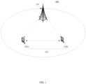
- FIG. 1 is a schematic diagram illustrating an exemplary wireless communication system 100 according to an embodiment of the present application.
- the wireless communication system 100 includes at least one BS 101 and at least one UE 102.
- the wireless communication system 100 includes one BS 101 and two UEs 102 (e.g., a UE 102a and a UE 102b) for illustrative purpose.
- a specific number of BS 101 and UEs 102 are depicted in FIG. 1 , it is contemplated that any number of BSs 101 and UEs 102 may be included in the wireless communication system 100.
- the BS 101 may also be referred to as an access point, an access terminal, a base, a macro cell, a node-B, an enhanced node B (eNB), a gNB, a home node-B, a relay node, or a device, or described using other terminology used in the art.
- the BS 101 is generally part of a radio access network that may include a controller communicably coupled to the BS 101.
- the UE(s) 102 may include computing devices, such as desktop computers, laptop computers, personal digital assistants (PDAs), tablet computers, smart televisions (e.g., televisions connected to the Internet), set-top boxes, game consoles, security systems (including security cameras), vehicle on-board computers, network devices (e.g., routers, switches, and modems), or the like.
- the UE(s) 102 may include a portable wireless communication device, a smart phone, a cellular telephone, a flip phone, a device having a subscriber identity module, a personal computer, a selective call receiver, or any other device that is capable of sending and receiving communication signals on a wireless network.
- the UE(s) 102 may include wearable devices, such as smart watches, fitness bands, optical head-mounted displays, or the like. Moreover, the UE(s) 102 may be referred to as a subscriber unit, a mobile, a mobile station, a user, a terminal, a mobile terminal, a wireless terminal, a fixed terminal, a subscriber station, a user terminal, or a device, or described using other terminology used in the art.
- the wireless communication system 100 is compatible with any type of network that is capable of sending and receiving wireless communication signals.
- the wireless communication system 100 is compatible with a wireless communication network, a cellular telephone network, a time division multiple access (TDMA)-based network, a code division multiple access (CDMA)-based network, an orthogonal frequency division multiple access (OFDMA)-based network, an LTE network, a 3GPP-based network, a 3GPP 5G network, a satellite communications network, a high altitude platform network, and/or other communications networks.
- TDMA time division multiple access
- CDMA code division multiple access
- OFDMA orthogonal frequency division multiple access
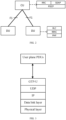
- FIG. 2 is a schematic diagram illustrating an internal structure of a BS according to some embodiments of the present application.
- the internal structure of a BS may be split into a central unit (CU) and at least one distributed unit (DU) (e.g., two DUs shown in FIG. 2 ).
- a central unit e.g., the BS 101 in FIG. 1
- DU distributed unit
- the CU and DU are connected with each other by an interface called F 1 as specified in 3GPP standard documents.
- the radio resource control (RRC) layer functionality, the service data adaptation protocol (SDAP) functionality, and the PDCP layer functionality are located in the CU.
- the radio link control (RLC) layer functionality, the medium access control (MAC) layer functionality, and the physical (PHY) layer functionality are located in the DU.
- a NR user plane protocol is located in the user plane of the radio network layer over either the Xn interface or the X2 interface or the F1 interface as specified in 3GPP standard documents.
- the NR user plane protocol may be used to convey control information related to the user data flow management of data radio bearers.
- Each NR user plane protocol instance is associated to one data radio bearer only.
- the user plane protocol may include a physical layer, a data link layer, an internet protocol (IP) layer, a user datagram protocol (UDP) layer, a GTP-U layer, and a user plane protocol layer.
- IP internet protocol
- UDP user datagram protocol
- GTP-U GTP-U layer
- PDU user plane protocol data unit
- RAN radio access network
- the user plane protocol layer may be used for flow control of user data packets transferred from the node hosting PDCP (e.g., the CU or the CU-UP) to the corresponding node (e.g., the DU).
- the user plane protocols may include the following information:
- the BS may transmit same MBS data to one or more UEs (e.g., UE 102a and UE 102b).
- the MBS data may be transmitted to the UE 102a and UE 102b via a PTM mode.
- the MBS data may be respectively transmitted to the UE 102a and UE 102b via a PTP mode.
- the PTM mode may refer to transmitting same MBS data to one or more UEs (e.g., UE 102a and UE 102b) via a multicast mode.
- the MBS data may be transmitted to the one or more UEs via a multicast data radio bearer (M-DRB).
- M-DRB may refer to a radio bearer or an RLC bearer for data transmission via a PTM mode.
- the M-DRB is scrambled by a group radio network temporary identifier (G-RNTI) in at least one cell.
- G-RNTI group radio network temporary identifier
- the M-DRB can also be named as multicast radio bearer (MRB).
- the PTP mode may refer to transmitting MBS data to a UE (e.g., UE 102a or UE 102b) via a unicast mode.
- the MBS data may be transmitted to the UE via a unicast data radio bearer (U-DRB).
- U-DRB may refer to a radio bearer or an RLC bearer for data transmission via a PTP mode.
- the U-DRB is scrambled by a cell radio network temporary identifier (C-RNTI).
- C-RNTI cell radio network temporary identifier
- the U-DRB can also be named as data radio bearer (DRB).
- the PTP-PTM dynamic switching is one of key features.
- the BS makes the decision on using a PTP mode or PTM mode over the radio.
- whether the CU or DU makes the decision on using a PTP mode or PTM mode has not been determined in 3GPP standard documents. Since the PTP-PTM switching is expected to be dynamic, using control signaling to indicate the switching may cause signaling overhead and delay between the CU and the DU. In this case, how to support more efficient dynamic switching between the PTP mode and the PTM mode needs to be further studied.
- PDCP retransmission may be supported for an MBS session or radio bearer.
- F1-U user plane protocol of F1 interface
- new transmission data e.g., new transmission PDCP PDU
- retransmission data e.g., retransmission PDCP PDU
- the DU should transmit the retransmission data to the UE first. In this case, how to distinguish the new transmission data and the retransmission data by the DU needs to be further studied.
- Embodiments of the present application may provide technical solutions for MBS, which can at least support more efficient dynamic PTP-PTM switching for MBS and/or distinguish new transmission data and retransmission data for MBS. More details on embodiments of the present application will be illustrated in the following text in combination with the appended drawings.
- FIG. 4 is a flow chart illustrating a method for MBS according to some embodiments of the present application. Although the method is illustrated in a system level by a transmitting side and a receiving side, persons skilled in the art can understand that the method implemented in the transmitting side and that implemented in the receiving side can be separately implemented and incorporated by other apparatus with the like functions.
- the transmitting side may determine whether to activate or deactivate a PTP mode to provide an MBS to a UE.
- the transmitting side may be a CU or a DU as shown in FIG. 2 .
- the MBS e.g., the MBS data
- the MBS may be provided to the UE by a PTM mode and/or a PTP mode, or the MBS may have not been provided to the UE by any mode (e.g., the data transmission of the MBS to the UE may have not started).
- Whether to activate or deactivate a PTP mode may be determined based on information such as quality of service (QoS) requirements for the MBS session, number of joined UEs for the MBS session, UE individual feedback on reception quality, and/or other criteria.
- QoS quality of service
- the transmitting side may transmit a data transmission indication to activate or deactivate the PTP mode to the receiving side via a user plane protocol (e.g., user plane protocol as shown in FIG. 3 ) of a network interface (e.g., F1 interface) between the transmitting side and the receiving side.
- a user plane protocol e.g., user plane protocol as shown in FIG. 3
- a network interface e.g., F1 interface
- the transmitting side may transmit the data transmission indication to activate the PTP mode.
- the transmitting side may transmit the data transmission indication to deactivate the PTP mode.
- the data transmission indication to activate or deactivate the PTP mode may be used to switch between the PTP and PTM modes.
- the data transmission indication to activate the PTP mode may be used to switch from the PTM mode to the PTP mode for data transmission to the UE or switch from the PTM mode to both the PTM and PTP modes for data transmission or activate the PTP mode.
- the data transmission indication to deactivate the PTP mode may be used to switch from the PTP mode to the PTM mode for data transmission to the UE or deactivate the PTP mode.
- the receiving side may also be a CU or a DU as shown in FIG. 2 .
- the receiving side may be a DU.
- the receiving side may be a CU.
- the receiving side may receive the data transmission indication to activate or deactivate the PTP mode via the user plane protocol of the network interface.
- the transmitting side may be a DU and the receiving side may be a CU.
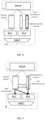
- FIG. 5 illustrates an example of transmitting an indication to activate or deactivate a PTP mode from a DU to a CU according to some embodiments of the present application.
- the CU of a BS (e.g., BS 101) shown in FIG. 5 may include a PDCP entity and the DU of the BS shown in FIG. 5 may include two RLC entities and a MAC entity.
- the CU may also include RRC entity and SDAP entity as shown in FIG. 2 and the DU may also include a PHY entity as shown in FIG. 2 .
- a shared tunnel for PTM transmission may be established between the CU and the DU.
- the shared tunnel may be used to transmit data (e.g., PDCP PDU) to the DU such that DU may transmit the data to one or more UEs (e.g., UE 102a and UE 102b) by a PTM mode.
- the data received from the shared tunnel may be delivered to one RLC entity of the two RLC entities for the PTM transmission.
- the shared tunnel may be an F1-U GTP-U tunnel.
- an individual tunnel for PTP transmission may be established between the CU and the DU.
- the individual tunnel may be used to transmit data (e.g., PDCP PDU) to the DU such that the DU may transmit the data to the UE by a PTP mode.
- the data received from the individual tunnel by the DU may be delivered to the other RLC entity of the two RLC entities for the PTP transmission. That is, the PTM transmission and the PTP transmission may have two different RLC entities (or RLC bearers).
- the individual tunnel may be an F1-U GTP-U tunnel.
- the DU may determine to activate a PTP mode. After determining to activate the PTP mode, the DU may transmit a data transmission indication to activate the PTP mode via the individual tunnel established for PTP transmission for the UE to the CU.
- the indication may be transmitted in a frame via the user plane protocol as shown in FIG. 2 .
- the frame may be a DL DATA DELIVERY STATUS frame as specified in 3GPP standard document TS 38.425.
- the frame may be any other frame transmitted via the user plane protocol as shown in FIG. 2 .
- the data transmission indication may be a one-bit field in the frame.
- the CU may start data transmission (e.g., start to transmit PDCP PDU(s)) of the MBS session or MBS radio bearer to the DU via the individual tunnel immediately.
- the DU may transmit the PDCP PDU(s) via a PTP leg (or via a PTP RLC bearer, or via an RLC entity for the PTP transmission) to the UE.
- the DU may also include at least one SN (or at least one count value) of at least one PDCP PDU in the frame. Then, after receiving the frame, the CU may transmit the at least one PDCP PDU indicated by the at least one SN (or at least one count value) via the individual tunnel to the DU. After receiving the at least one PDCP PDU transmitted from the individual tunnel, the DU may transmit the at least one PDCP PDU via a PTP leg (or via a PTP RLC bearer, or via an RLC entity for the PTP transmission) to the UE.
- the DU may also include an SN (or a count value) of a PDCP PDU in the frame. Then, after receiving the frame, the CU may start data transmission via the individual tunnel from the PDCP PDU indicated by the SN or the count value included in the frame. Also, the DU may start data reception via the individual tunnel from the PDCP PDU indicated by the SN. For example, assuming that the SN of PDCP PDU included in the frame is "5,” after receiving the frame, the CU may transmit the PDCP PDU with an SN of "5" and its succeeding PDCP PDU(s) via the individual tunnel.
- the DU may transmit the PDCP PDU(s) via a PTP leg (or via a PTP RLC bearer, or via an RLC entity for the PTP transmission) to the UE.
- the DU may determine to deactivate the PTP mode (i.e., switch from the PTP mode to the PTM mode). After determining to deactivate the PTP mode, the DU may transmit a data transmission indication to deactivate the PTP mode via the individual tunnel established for PTP transmission for the UE to the CU.
- the indication may be transmitted in a frame via the user plane protocol as shown in FIG. 2 .
- the frame may be a DL DATA DELIVERY STATUS frame as specified in 3GPP standard document TS 38.425.
- the frame may be any other frame transmitted via the user plane protocol as shown in FIG. 2 .
- the CU may stop data transmission (e.g., stop to transmit PDCP PDU(s)) of the MBS session or MBS radio bearer to the DU via the individual tunnel immediately.
- the DU may also include an SN (or a count value) of a PDCP PDU in the frame. Then, after receiving the frame, the CU may stop data transmission via the individual tunnel from the PDCP PDU indicated by the SN or the count value included in the frame. Also, the DU may stop data reception via the individual tunnel from the PDCP PDU indicated by the SN. For example, assuming that the SN of PDCP PDU included in the frame is "5,” after receiving the frame, the CU may not transmit the PDCP PDU with an SN of "5" and its succeeding PDCP PDU(s) via the individual tunnel.
- Table 1 shows an example of a DL DATA DELIVERY STATUS frame, which includes the indication (e.g., the data transmission indication) to activate or deactivate the PTP mode and an SN of a PDCP PDU.
- the indication e.g., the data transmission indication
- the DL DATA DELIVERY STATUS frame may also include the following parameters, which are the same as those defined in 3GPP standard document TS 38.425:
- the transmitting side may be a CU and the receiving side may be a DU.
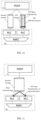
- FIG. 6 illustrates an example of transmitting an indication to activate or deactivate a PTP mode from a CU to a DU according to some embodiments of the present application.
- the CU and the DU in FIG. 6 may be the same as those in FIG. 5 .
- the difference between FIG. 6 and FIG. 5 is that in FIG. 6 , a shared tunnel for both PTM transmission and PTP transmission may be established between the CU and the DU.
- the shared tunnel may be an F1-U GTP-U tunnel.
- the shared tunnel may be used for data to be transmitted to one or more UEs via a PTM mode and may also be used for data to be transmitted to a UE via a PTP mode.
- the DU may deliver the data to one RLC entity of the two RLC entities for the PTM transmission.
- the DU may deliver the data to the other RLC entity of the two RLC entities for the PTP transmission. That is, the PTM transmission and the PTP transmission may have two different RLC entities (or RLC bearers).
- the CU may determine to activate a PTP mode for the UE. After determining to activate the PTP mode, the CU may transmit a data transmission indication to activate the PTP mode via the shared tunnel for PTP transmission and PTM transmission to the DU.
- the data transmission indication may be transmitted in a frame via a user plane protocol as shown in FIG. 2 .
- the frame may be a DL USER DATA frame as specified in 3GPP standard document TS 38.425.
- the frame may be any other frame transmitted via the user plane protocol as shown in FIG. 2 .
- the frame need indicate the UE which is associated with the data transmission indication.
- the data transmission indication to activate the PTP mode may include an ID associated with the UE.
- the data transmission indication to activate the PTP mode may be an ID associated with the UE. That is, the ID associated with the UE may be an implicit PTP activation indication. If the ID associated with the UE is present in the frame, the DU may treat it as a data transmission indication to activate the PTP mode.
- the frame in addition to an explicit data transmission indication to activate the PTP mode, the frame may further include an ID associated with the UE. The ID associated with the UE may be a UE ID or a UE index.
- the DU may start to transmit the PDCP PDU(s) via the PTP leg or PTP RLC bearer to the UE indicated by the ID immediately.
- the CU may also include an SN (or a count value) of a PDCP PDU in the frame. Then, after receiving the frame, the DU may start data transmission (i.e., transmitting at least one PDCP PDU) to the UE indicated by the ID included in the frame via a PTP leg (or via a PTP RLC bearer, or via an RLC entity for the PTP transmission) from the PDCP PDU indicated by the SN or the count value included in the frame.
- a PTP leg or via a PTP RLC bearer, or via an RLC entity for the PTP transmission
- the DU may transmit the PDCP PDU with an SN of "5" and its succeeding PDCP PDU(s) via a PTP leg (or via a PTP RLC bearer, or via an RLC entity for the PTP transmission) to the UE.
- the CU may determine to deactivate the PTP mode for the UE (i.e., switch from the PTP mode to the PTM mode). After determining to deactivate the PTP mode, the CU may transmit a data transmission indication to deactivate the PTP mode via the shared tunnel for PTP transmission and PTM transmission to the DU.
- the indication may be transmitted in a frame via the user plane protocol as shown in FIG. 2 .
- the frame may be a DL USER DATA frame as specified in 3GPP standard document TS 38.425.
- the frame may be any other frame transmitted via the user plane protocol as shown in FIG. 2 .
- the data transmission indication to deactivate the PTP mode may include an ID associated with the UE, or the data transmission indication to deactivate the PTP mode may be an ID associated with the UE, or the frame including the data transmission indication may also include an ID associated with the UE.
- the ID associated with the UE may be a UE ID or a UE index.
- the DU may stop to transmit the PDCP PDU(s) via the PTP leg or PTP RLC bearer to the UE indicated by the ID immediately.
- the CU may also include an SN (or a count value) of a PDCP PDU in the frame. Then, after receiving the frame, the DU may stop data transmission (i.e., stop transmitting PDCP PDU(s)) to the UE indicated by the ID included in the frame via a PTP leg (or via a PTP RLC bearer, or via an RLC entity for the PTP transmission) from the PDCP PDU indicated by the SN or the count value included in the frame.
- a PTP leg or via a PTP RLC bearer, or via an RLC entity for the PTP transmission
- the DU may not transmit PDCP PDU with an SN of "5" and its succeeding PDCP PDU(s) via a PTP leg (or via a PTP RLC bearer, or via an RLC entity for the PTP transmission) to the UE.
- Table 2 shows an example of a DL USER DATA frame, which includes the indication (e.g., the data transmission indication) to activate or deactivate the PTP mode, an ID associated with a UE, and an SN of a PDCP PDU.
- the indication e.g., the data transmission indication
- the DL USER DATA frame may also include the following parameters, which are the same as those defined in 3GPP standard document TS 38.425:
- FIG. 7 is a flow chart illustrating a method for MBS according to some other embodiments of the present application.
- a CU e.g., the CU shown in FIG. 2
- a DU e.g., the DU in FIG. 2
- persons skilled in the art can understand that the method implemented in the CU and that implemented in the DU can be separately implemented and incorporated by other apparatus with the like functions.
- the CU may transmit a set of data packets associated with an MBS session to the DU.
- a data packet may be a PDCP PDU.
- the DU may transmit the set of data packets to a UE (e.g., UE 102a or UE 102b) via a PTM mode or via a PTP mode.
- the UE may transmit a status report (e.g., a PDCP status report) to the CU.
- the status report may indicate the receiving status of the set of data packets.
- the status report may indicate which data packets of the set of data packets are successfully received and/or which data packets of the set of data packets are not successfully received by the UE.
- the CU may identify the receiving status of the set of data packets. Then, at step 704, the CU may retransmit a subset of the set of data packets in response to the status report indicating that the subset is not successfully received by the UE to the DU.
- the subset may include a portion of data packets in the set of data packets or may include all data packets in the set of data packets.
- the DU may transmit the retransmitted subset to the UE at a higher priority than new data packets at step 706.
- the DU need know which data packets are new data packets and which data packets are retransmitted data packets.
- Embodiments of the present application may provide several methods for the DU to identify the retransmitted data packets.
- the subset of the set of data packets may be retransmitted via a retransmission tunnel.
- FIG. 8 illustrates an example of data retransmission according to some embodiments of the present application.
- the CU and the DU shown in FIG. 8 may be the same as those shown in FIG. 5 .
- a shared tunnel for PTM transmission may be established between the CU and the DU.
- the shared tunnel may be used to transmit data (e.g., PDCP PDU) to the DU such that DU may transmit the data to one or more UEs (e.g., UE 102a and UE 102b) by a PTM mode.
- the data received from the shared tunnel may be delivered to one RLC entity (or one RLC bearer) of the two RLC entities for the PTM transmission.
- the shared tunnel may be an F1-U GTP-U tunnel.
- a new transmission tunnel and a retransmission tunnel may be established between the CU and the DU, respectively.
- the new transmission tunnel may be used to transmit new data packets to the DU such that the DU may transmit the new data packets to the UE by a PTP mode.
- the retransmission tunnel may be used to transmit retransmitted data packets to the DU such that the DU may transmit the retransmitted data packets to the UE by a PTP mode.
- the data packets received from the new transmission tunnel and the retransmission tunnel by the DU may be delivered to the other RLC entity of the two RLC entities for the PTP transmission.
- the new transmission tunnel and the retransmission tunnel may be F1-U GTP-U tunnels.
- the CU Before retransmitting the subset of the set of data packets (even before transmitting the set of data packets, e.g., during an MBS bearer setup procedure), the CU may decide whether retransmission is needed or not for an MBS session or a radio bearer. If yes, the CU may transmit an indication for establishing a retransmission tunnel to the DU. After receiving the indication, the DU may allocates TNL information and transmit it back to the CU.
- the TNL information may include an IP address and a GTP-U TEID.
- the retransmission tunnel may be established. Then, the CU may retransmit the subset of the set of data packets via the retransmission tunnel with the TNL information to the DU.
- the DU may identity that the subset is retransmitted data packets based on the TNL information. Then, the DU may transmit the subset of the set of data packets to the UE at a higher priority than new data packets.
- FIG. 9 illustrates another example of data retransmission according to some other embodiments of the present application.
- the subset of the set of data packets may also be transmitted via a retransmission tunnel, which is the same as that shown in FIG. 8 .
- the shared tunnel established between the CU and the DU is for both PTM transmission and PTP new data transmission. That is, the shared tunnel may be used for data packets to be transmitted to one or more UEs via a PTM mode and may also be used for new data packets to be transmitted to a UE via a PTP mode.
- the shared tunnel may be an F 1-U GTP-U tunnel.
- the DU After receiving data packets to be transmitted by a PTM mode (i.e., PTM transmission) via the shared tunnel from the CU, the DU may deliver the data to one RLC entity of the two RLC entities for the PTM transmission. After receiving new data packets to be transmitted by a PTP mode (i.e., PTP new transmission) to a UE via the shared tunnel from the CU, the DU may deliver the data to the other RLC entity of the two RLC entities for the PTP transmission. After receiving data packets via the retransmission tunnel from the CU, the DU may identity that data packets are retransmitted data packets based on the TNL information of the retransmission tunnel and deliver the data packets to the same RLC entity as new data packets.
- PTM mode i.e., PTM transmission
- PTP new transmission i.e., PTP new transmission
- the subset of the set of data packets may be retransmitted via a PTP tunnel for both PTP new data packet transmission and PTP data packet retransmission.
- FIG. 10 illustrates an example of data retransmission according to some other embodiments of the present application.
- the CU and the DU shown in FIG. 10 may be the same as those shown in FIG. 5 .
- a shared tunnel for PTM transmission may be established between the CU and DU.
- the shared tunnel may be used to transmit data (e.g., PDCP PDU) to the DU such that DU may transmit the data to one or more UEs (e.g., UE 102a and UE 102b) by a PTM mode.
- the data received from the shared tunnel may be delivered to one RLC entity of the two RLC entities for the PTM transmission.
- the shared tunnel may be an F1-U GTP-U tunnel.
- a PTP tunnel for both PTP new data packet transmission and PTP data packet retransmission may be established between the CU and the DU.
- the CU may transmit a retransmission indication in a packet header of each data packet in the retransmitted subset to indicate that the corresponding data packet is a retransmitted data packet.
- the packet header may be a frame of a user plane protocol.
- the frame may be a DL USER DATA frame as specified in TS 38.425 or any other frame transmitted via the user plane protocol of the F1 interface between the CU and the DU.
- the DU may identify that the corresponding data packet in the retransmitted subset is a retransmitted data packet based on the retransmission indication.
- the subset of the set of data packets may be retransmitted via a shared tunnel for PTM transmission, PTP new data packet transmission, and PTP data packet retransmission.
- FIG. 11 illustrates an example of data retransmission according to some other embodiments of the present application.
- the CU and the DU shown in FIG. 10 may be the same as those shown in FIG. 6 .
- a shared tunnel for PTM transmission, PTP new data packet transmission, and PTP data packet retransmission may be established between the CU and the DU.
- the shared tunnel may be an F1-U GTP-U tunnel.
- the shared tunnel may be used to transmit data (e.g., PDCP PDU) to the DU such that DU may transmit the data to one or more UEs (e.g., UE 102a and UE 102b) by a PTM mode.
- the data to be transmitted by a PTM mode may be delivered to one RLC entity (or one RLC bearer) of the two RLC entities for the PTM transmission.
- the shared tunnel may also be used to transmit new data packets (e.g., PDCP PDUs) and retransmit data packets to the DU such that DU may transmit the new data packets and the retransmitted data packets to a UE (e.g., UE 102a or UE 102b) via a PTP mode.
- the new data packets and the retransmitted data packets to be transmitted by the DU may be delivered to the other RLC entity of the two RLC entities for the PTP transmission.
- the CU may transmit an identity (ID) associated with the UE in a frame via the user plane protocol.
- the frame may be a DL USER DATA frame as specified in TS 38.425 or any other frame transmitted via the user plane protocol of the F1 interface between the CU and the DU.
- the ID associated with the UE may be a UE ID or a UE index.
- the frame may also include SN information associated with the retransmitted subset of the set of data packets.
- the SN information may include a respective SN associated with each data packet in the retransmitted subset.
- the SN information may include an SN range associated with the retransmitted subset.
- the DU may identify that each data packet in the retransmitted subset is a retransmitted data packet based on the SN information and may know the UE for which the subset of the set of data packets is retransmitted.
- Table 3 shows an example of a DL USER DATA frame, which includes an ID associated with a UE and SN information for the retransmitted subset of the set of data packets.
- the DL USER DATA frame may also include a Retransmission SNs flag indicating the presence of the SN information.
- the parameters included in the DL USER DATA frame may be the same as those defined in 3GPP standard document TS 38.425.
- FIG. 12 illustrates a simplified block diagram of an apparatus for MBS according to some embodiments of the present application.
- the apparatus 1200 may be a CU or a DU as shown in FIG. 2 .
- the apparatus 1200 may include at least one non-transitory computer-readable medium 1202, at least one receiving circuitry 1204, at least one transmitting circuitry 1206, and at least one processor 1208.
- at least one receiving circuitry 1204 and at least one transmitting circuitry 1206 and be integrated into at least one transceiver.
- the at least one non-transitory computer-readable medium 1202 may have computer executable instructions stored therein.
- the at least one processor 1208 may be coupled to the at least one non-transitory computer-readable medium 1202, the at least one receiving circuitry 1204 and the at least one transmitting circuitry 1206.
- the computer executable instructions can be programmed to implement a method with the at least one receiving circuitry 1204, the at least one transmitting circuitry 1206 and the at least one processor 1208.
- the method can be a method according to an embodiment of the present application, for example, the method shown in FIG. 4 or 7 .
- the method according to embodiments of the present application can also be implemented on a programmed processor.
- the controllers, flowcharts, and modules may also be implemented on a general purpose or special purpose computer, a programmed microprocessor or microcontroller and peripheral integrated circuit elements, an integrated circuit, a hardware electronic or logic circuit such as a discrete element circuit, a programmable logic device, or the like.
- any device on which resides a finite state machine capable of implementing the flowcharts shown in the figures may be used to implement the processor functions of this application.
- an embodiment of the present application provides an apparatus for MBS, including a processor and a memory.
- Computer programmable instructions for implementing a method for MBS are stored in the memory, and the processor is configured to perform the computer programmable instructions to implement the method for MBS.
- the method may be a method as stated above or other method according to an embodiment of the present application.
- An alternative embodiment preferably implements the methods according to embodiments of the present application in a non-transitory, computer-readable storage medium storing computer programmable instructions.
- the instructions are preferably executed by computer-executable components preferably integrated with a network security system.
- the non-transitory, computer-readable storage medium may be stored on any suitable computer readable media such as RAMs, ROMs, flash memory, EEPROMs, optical storage devices (CD or DVD), hard drives, floppy drives, or any suitable device.
- the computer-executable component is preferably a processor but the instructions may alternatively or additionally be executed by any suitable dedicated hardware device.
- an embodiment of the present application provides a non-transitory, computer-readable storage medium having computer programmable instructions stored therein.
- the computer programmable instructions are configured to implement a method for MBS as stated above or other method according to an embodiment of the present application.
Landscapes
- Engineering & Computer Science (AREA)
- Computer Networks & Wireless Communication (AREA)
- Signal Processing (AREA)
- Multimedia (AREA)
- Mobile Radio Communication Systems (AREA)
Priority Applications (1)
| Application Number | Priority Date | Filing Date | Title |
|---|---|---|---|
| EP25150531.9A EP4514059A3 (de) | 2021-01-14 | 2021-01-14 | Verfahren und vorrichtungen für multicast- und broadcastdienste |
Applications Claiming Priority (3)
| Application Number | Priority Date | Filing Date | Title |
|---|---|---|---|
| PCT/CN2021/071812 WO2022151177A1 (en) | 2021-01-14 | 2021-01-14 | Methods and apparatuses for multicast and broadcast services |
| EP25150531.9A EP4514059A3 (de) | 2021-01-14 | 2021-01-14 | Verfahren und vorrichtungen für multicast- und broadcastdienste |
| EP21918385.2A EP4278624A4 (de) | 2021-01-14 | 2021-01-14 | Verfahren und vorrichtungen für multicast- und broadcastdienste |
Related Parent Applications (1)
| Application Number | Title | Priority Date | Filing Date |
|---|---|---|---|
| EP21918385.2A Division EP4278624A4 (de) | 2021-01-14 | 2021-01-14 | Verfahren und vorrichtungen für multicast- und broadcastdienste |
Publications (2)
| Publication Number | Publication Date |
|---|---|
| EP4514059A2 true EP4514059A2 (de) | 2025-02-26 |
| EP4514059A3 EP4514059A3 (de) | 2025-05-14 |
Family
ID=82447793
Family Applications (2)
| Application Number | Title | Priority Date | Filing Date |
|---|---|---|---|
| EP25150531.9A Pending EP4514059A3 (de) | 2021-01-14 | 2021-01-14 | Verfahren und vorrichtungen für multicast- und broadcastdienste |
| EP21918385.2A Withdrawn EP4278624A4 (de) | 2021-01-14 | 2021-01-14 | Verfahren und vorrichtungen für multicast- und broadcastdienste |
Family Applications After (1)
| Application Number | Title | Priority Date | Filing Date |
|---|---|---|---|
| EP21918385.2A Withdrawn EP4278624A4 (de) | 2021-01-14 | 2021-01-14 | Verfahren und vorrichtungen für multicast- und broadcastdienste |
Country Status (4)
| Country | Link |
|---|---|
| US (1) | US20240080216A1 (de) |
| EP (2) | EP4514059A3 (de) |
| CN (1) | CN116746171A (de) |
| WO (1) | WO2022151177A1 (de) |
Families Citing this family (3)
| Publication number | Priority date | Publication date | Assignee | Title |
|---|---|---|---|---|
| CN113518315B (zh) * | 2020-03-27 | 2023-03-24 | 华为技术有限公司 | 一种配置无线承载的方法、装置及系统 |
| CN115278548A (zh) * | 2021-04-30 | 2022-11-01 | 华为技术有限公司 | 一种数据传输方法及装置 |
| US20240389137A1 (en) * | 2021-09-17 | 2024-11-21 | Lg Electronics Inc. | Method and device for performing sensing procedure in wireless lan system |
Family Cites Families (9)
| Publication number | Priority date | Publication date | Assignee | Title |
|---|---|---|---|---|
| US7536622B2 (en) * | 2004-03-29 | 2009-05-19 | Nokia Corporation | Data repair enhancements for multicast/broadcast data distribution |
| EP1833217A1 (de) * | 2006-03-09 | 2007-09-12 | Matsushita Electric Industrial Co., Ltd. | Bereitstellung von Dienstdaten eines bidirektionalen Dienstes (IMS, z.B: PoC, Konferenz) durch Verwendung eines downlink multicast Dienstes (z.B: MBMS) |
| EP2033374A2 (de) * | 2006-06-13 | 2009-03-11 | Aware, Inc. | Punkt-zu-punkt- und punkt-zu-mehrpunkt-kommunikationen |
| US9602297B2 (en) * | 2007-03-12 | 2017-03-21 | Nokia Technologies Oy | Establishment of reliable multicast/broadcast in a wireless network |
| US7903540B2 (en) * | 2007-08-02 | 2011-03-08 | Alvarion Ltd. | Method and device for synchronization in wireless networks |
| US8321741B2 (en) * | 2008-05-05 | 2012-11-27 | Industrial Technology Research Institute | System and apparatus for providing an adaptive control mechanism for wireless communications |
| US8699398B2 (en) * | 2011-11-19 | 2014-04-15 | Motorola Solutions, Inc. | Dynamically switching mobile stations between point-to-point and point-to-multipoint operating modes |
| CN110662270B (zh) * | 2018-06-28 | 2021-05-18 | 华为技术有限公司 | 通信方法及装置 |
| US11134469B2 (en) * | 2018-08-21 | 2021-09-28 | Qualcomm Incorporated | Reliability for multicast transmissions |
-
2021
- 2021-01-14 CN CN202180090167.XA patent/CN116746171A/zh active Pending
- 2021-01-14 WO PCT/CN2021/071812 patent/WO2022151177A1/en not_active Ceased
- 2021-01-14 EP EP25150531.9A patent/EP4514059A3/de active Pending
- 2021-01-14 EP EP21918385.2A patent/EP4278624A4/de not_active Withdrawn
- 2021-01-14 US US18/261,434 patent/US20240080216A1/en active Pending
Non-Patent Citations (1)
| Title |
|---|
| NOKIA ET AL: "Summary of Offline Discussion on MBS PTP- PTM Dynamic Change", vol. RAN WG3, no. Online; 20201102 - 20201112, 6 November 2020 (2020-11-06), XP052399927, Retrieved from the Internet <URL:https://ftp.3gpp.org/tsg_ran/WG3_Iu/TSGR3_110-e/Inbox/R3-206909.zip R3-206909_Summary_PTPPTMswitch_v2.doc> [retrieved on 20201106] * |
Also Published As
| Publication number | Publication date |
|---|---|
| US20240080216A1 (en) | 2024-03-07 |
| EP4514059A3 (de) | 2025-05-14 |
| EP4278624A1 (de) | 2023-11-22 |
| CN116746171A (zh) | 2023-09-12 |
| EP4278624A4 (de) | 2024-08-21 |
| WO2022151177A1 (en) | 2022-07-21 |
Similar Documents
| Publication | Publication Date | Title |
|---|---|---|
| US12150203B2 (en) | Communication method and related product | |
| US11984989B2 (en) | Transmission method and apparatus | |
| JP7614329B2 (ja) | マルチキャストおよびブロードキャストサービスのための方法および装置 | |
| CN110999531B (zh) | 通信装置、基础设施设备、通信系统和方法 | |
| CN113853808A (zh) | 一种多播传输控制方法以及相关设备 | |
| US12574805B2 (en) | Methods and apparatuses for data transmission for multicast broadcast service | |
| EP4514059A2 (de) | Verfahren und vorrichtungen für multicast- und broadcastdienste | |
| WO2022151297A1 (zh) | 数据传输方法及装置 | |
| US20240056901A1 (en) | Method and apparatus for multicast and broadcast services | |
| US20230292200A1 (en) | Method and apparatus for multicast and broadcast services | |
| EP4142402A1 (de) | Kommunikationssteuerungsverfahren und benutzergerät | |
| US20260075389A1 (en) | Communication control method | |
| CN112312575A (zh) | 一种通信方法及装置 | |
| US20240236619A1 (en) | Method and apparatus for multicast and broadcast services | |
| CN116349290B (zh) | 通信控制方法、基站、用户设备以及处理器 | |
| WO2022000253A1 (en) | Methods and apparatus of reliable multicast transmission with compact protocol stack | |
| US12549999B2 (en) | Method and apparatus for multicast and broadcast services | |
| US12598629B2 (en) | Methods and apparatuses for exchanging configuration information regarding a MRB in a MR-DC scenario | |
| CN116235625B (zh) | 通信方法、设备和计算机存储介质 | |
| US20260052358A1 (en) | Method and apparatus of supporting multicast and broadcast services | |
| WO2023060402A1 (en) | Method and apparatus for multicast and broadcast services | |
| WO2009102166A2 (ko) | 이동 통신 시스템에서 우선 순위화 비트 레이트를 이용하여 데이터를 전송하는 방법 및 장치 | |
| WO2018186782A1 (en) | Transport of rrc messages in dual connectivity communication |
Legal Events
| Date | Code | Title | Description |
|---|---|---|---|
| PUAI | Public reference made under article 153(3) epc to a published international application that has entered the european phase |
Free format text: ORIGINAL CODE: 0009012 |
|
| STAA | Information on the status of an ep patent application or granted ep patent |
Free format text: STATUS: THE APPLICATION HAS BEEN PUBLISHED |
|
| AC | Divisional application: reference to earlier application |
Ref document number: 4278624 Country of ref document: EP Kind code of ref document: P |
|
| AK | Designated contracting states |
Kind code of ref document: A2 Designated state(s): AL AT BE BG CH CY CZ DE DK EE ES FI FR GB GR HR HU IE IS IT LI LT LU LV MC MK MT NL NO PL PT RO RS SE SI SK SM TR |
|
| REG | Reference to a national code |
Ref country code: DE Ref legal event code: R079 Free format text: PREVIOUS MAIN CLASS: H04W0080020000 Ipc: H04W0004060000 |
|
| PUAL | Search report despatched |
Free format text: ORIGINAL CODE: 0009013 |
|
| AK | Designated contracting states |
Kind code of ref document: A3 Designated state(s): AL AT BE BG CH CY CZ DE DK EE ES FI FR GB GR HR HU IE IS IT LI LT LU LV MC MK MT NL NO PL PT RO RS SE SI SK SM TR |
|
| RIC1 | Information provided on ipc code assigned before grant |
Ipc: H04W 80/02 20090101ALI20250407BHEP Ipc: H04W 76/40 20180101ALI20250407BHEP Ipc: H04W 76/12 20180101ALI20250407BHEP Ipc: H04W 4/06 20090101AFI20250407BHEP |
|
| STAA | Information on the status of an ep patent application or granted ep patent |
Free format text: STATUS: REQUEST FOR EXAMINATION WAS MADE |
|
| 17P | Request for examination filed |
Effective date: 20251109 |
|
| STAA | Information on the status of an ep patent application or granted ep patent |
Free format text: STATUS: EXAMINATION IS IN PROGRESS |
|
| 17Q | First examination report despatched |
Effective date: 20260122 |