EP4514083A1 - Plaque de conduction de chaleur, appareil de dissipation de chaleur et dispositif électronique - Google Patents
Plaque de conduction de chaleur, appareil de dissipation de chaleur et dispositif électronique Download PDFInfo
- Publication number
- EP4514083A1 EP4514083A1 EP23829372.4A EP23829372A EP4514083A1 EP 4514083 A1 EP4514083 A1 EP 4514083A1 EP 23829372 A EP23829372 A EP 23829372A EP 4514083 A1 EP4514083 A1 EP 4514083A1
- Authority
- EP
- European Patent Office
- Prior art keywords
- heat dissipation
- heat
- dissipation channel
- conducting plate
- channel
- Prior art date
- Legal status (The legal status is an assumption and is not a legal conclusion. Google has not performed a legal analysis and makes no representation as to the accuracy of the status listed.)
- Pending
Links
Images





Classifications
-
- F—MECHANICAL ENGINEERING; LIGHTING; HEATING; WEAPONS; BLASTING
- F28—HEAT EXCHANGE IN GENERAL
- F28F—DETAILS OF HEAT-EXCHANGE AND HEAT-TRANSFER APPARATUS, OF GENERAL APPLICATION
- F28F3/00—Plate-like or laminated elements; Assemblies of plate-like or laminated elements
- F28F3/12—Elements constructed in the shape of a hollow panel, e.g. with channels
-
- H—ELECTRICITY
- H05—ELECTRIC TECHNIQUES NOT OTHERWISE PROVIDED FOR
- H05K—PRINTED CIRCUITS; CASINGS OR CONSTRUCTIONAL DETAILS OF ELECTRIC APPARATUS; MANUFACTURE OF ASSEMBLAGES OF ELECTRICAL COMPONENTS
- H05K7/00—Constructional details common to different types of electric apparatus
- H05K7/20—Modifications to facilitate cooling, ventilating, or heating
- H05K7/2029—Modifications to facilitate cooling, ventilating, or heating using a liquid coolant with phase change in electronic enclosures
- H05K7/20327—Accessories for moving fluid, for connecting fluid conduits, for distributing fluid or for preventing leakage, e.g. pumps, tanks or manifolds
-
- F—MECHANICAL ENGINEERING; LIGHTING; HEATING; WEAPONS; BLASTING
- F28—HEAT EXCHANGE IN GENERAL
- F28F—DETAILS OF HEAT-EXCHANGE AND HEAT-TRANSFER APPARATUS, OF GENERAL APPLICATION
- F28F3/00—Plate-like or laminated elements; Assemblies of plate-like or laminated elements
- F28F3/02—Elements or assemblies thereof with means for increasing heat-transfer area, e.g. with fins, with recesses, with corrugations
- F28F3/04—Elements or assemblies thereof with means for increasing heat-transfer area, e.g. with fins, with recesses, with corrugations the means being integral with the element
- F28F3/042—Elements or assemblies thereof with means for increasing heat-transfer area, e.g. with fins, with recesses, with corrugations the means being integral with the element in the form of local deformations of the element
- F28F3/046—Elements or assemblies thereof with means for increasing heat-transfer area, e.g. with fins, with recesses, with corrugations the means being integral with the element in the form of local deformations of the element the deformations being linear, e.g. corrugations
-
- H—ELECTRICITY
- H10—SEMICONDUCTOR DEVICES; ELECTRIC SOLID-STATE DEVICES NOT OTHERWISE PROVIDED FOR
- H10W—GENERIC PACKAGES, INTERCONNECTIONS, CONNECTORS OR OTHER CONSTRUCTIONAL DETAILS OF DEVICES COVERED BY CLASS H10
- H10W40/00—Arrangements for thermal protection or thermal control
- H10W40/70—Fillings or auxiliary members in containers or in encapsulations for thermal protection or control
- H10W40/73—Fillings or auxiliary members in containers or in encapsulations for thermal protection or control for cooling by change of state
-
- F—MECHANICAL ENGINEERING; LIGHTING; HEATING; WEAPONS; BLASTING
- F28—HEAT EXCHANGE IN GENERAL
- F28D—HEAT-EXCHANGE APPARATUS, NOT PROVIDED FOR IN ANOTHER SUBCLASS, IN WHICH THE HEAT-EXCHANGE MEDIA DO NOT COME INTO DIRECT CONTACT
- F28D21/00—Heat-exchange apparatus not covered by any of the groups F28D1/00 - F28D20/00
- F28D2021/0019—Other heat exchangers for particular applications; Heat exchange systems not otherwise provided for
- F28D2021/0028—Other heat exchangers for particular applications; Heat exchange systems not otherwise provided for for cooling heat generating elements, e.g. for cooling electronic components or electric devices
- F28D2021/0029—Heat sinks
-
- H—ELECTRICITY
- H10—SEMICONDUCTOR DEVICES; ELECTRIC SOLID-STATE DEVICES NOT OTHERWISE PROVIDED FOR
- H10W—GENERIC PACKAGES, INTERCONNECTIONS, CONNECTORS OR OTHER CONSTRUCTIONAL DETAILS OF DEVICES COVERED BY CLASS H10
- H10W40/00—Arrangements for thermal protection or thermal control
- H10W40/20—Arrangements for cooling
- H10W40/22—Arrangements for cooling characterised by their shape, e.g. having conical or cylindrical projections
- H10W40/226—Arrangements for cooling characterised by their shape, e.g. having conical or cylindrical projections characterised by projecting parts, e.g. fins to increase surface area
-
- H—ELECTRICITY
- H10—SEMICONDUCTOR DEVICES; ELECTRIC SOLID-STATE DEVICES NOT OTHERWISE PROVIDED FOR
- H10W—GENERIC PACKAGES, INTERCONNECTIONS, CONNECTORS OR OTHER CONSTRUCTIONAL DETAILS OF DEVICES COVERED BY CLASS H10
- H10W40/00—Arrangements for thermal protection or thermal control
- H10W40/20—Arrangements for cooling
- H10W40/22—Arrangements for cooling characterised by their shape, e.g. having conical or cylindrical projections
- H10W40/226—Arrangements for cooling characterised by their shape, e.g. having conical or cylindrical projections characterised by projecting parts, e.g. fins to increase surface area
- H10W40/228—Arrangements for cooling characterised by their shape, e.g. having conical or cylindrical projections characterised by projecting parts, e.g. fins to increase surface area the projecting parts being wire-shaped or pin-shaped
Definitions
- Embodiments of the present disclosure relate to the technical field of heat dissipation, and more particularly, to a heat conducting plate, a heat dissipation apparatus, and an electronic device.
- Embodiments of the present disclosure provide a heat conducting plate, a heat dissipation apparatus, and an electronic device.
- an embodiment provides a heat conducting plate, including: a heat conducting plate body, and a first heat dissipation zone, a second heat dissipation zone, and a third heat dissipation zone which are arranged on the heat conducting plate body.
- the first heat dissipation zone is arranged adjacent to a first side of the heat conducting plate body.
- the first side of the heat conducting plate body is configured as a heat input end.
- the second heat dissipation zone is arranged adjacent to the first heat dissipation zone, and the second heat dissipation zone is provided with a second heat dissipation channel.
- the third heat dissipation zone is arranged adjacent to the first heat dissipation zone and the second heat dissipation zone, and the third heat dissipation zone is provided with a third heat dissipation channel.
- the second heat dissipation channel includes at least a mesh-shaped channel.
- the third heat dissipation channel includes at least a strip-shaped channel. The second heat dissipation channel is communicated with the third heat dissipation channel.
- an embodiment provides a heat dissipation apparatus, including a base and the heat conducting plate according to the first aspect.
- the base is connected to the heat conducting plate.
- an embodiment provides an electronic device, including the heat conducting plate according to the first aspect, or including the heat dissipation apparatus according to the second aspect.
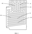
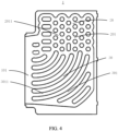
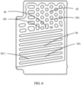
- an embodiment of the present disclosure provides a heat conducting plate 1, including: a heat conducting plate body, and a first heat dissipation zone 10, a second heat dissipation zone 20, and a third heat dissipation zone 30 which are arranged on the heat conducting plate body.
- the first heat dissipation zone 10 is arranged adjacent to a first side of the heat conducting plate body.
- the first side of the heat conducting plate body is configured as a heat input end.
- the second heat dissipation zone 20 is arranged adjacent to the first heat dissipation zone 10, and the second heat dissipation zone 20 is provided with a second heat dissipation channel 201.
- the third heat dissipation zone 30 is arranged adjacent to the first heat dissipation zone 10 and the second heat dissipation zone 20, and the third heat dissipation zone 30 is provided with a third heat dissipation channel 301.
- the second heat dissipation channel 201 is communicated with the third heat dissipation channel 301.
- the heat conducting plate 1 further includes a heat-conducting working medium configured to flow in the second heat dissipation channel 201 and the third heat dissipation channel 301.
- the second heat dissipation channel 201 is configured to liquefy at least part of the heat-conducting working medium.
- the liquefied heat-conducting working medium in the second heat dissipation channel 201 flows to the third heat dissipation channel 301 through the second heat dissipation channel 201.
- the second heat dissipation channel 201 has a different structure from the third heat dissipation channel 301.
- the second heat dissipation channel 201 includes at least a mesh-shaped channel.
- the mesh-shaped channel is a non-directional array channel that helps diffuse a vapor-state heat-conducting working medium.
- the vapor-state heat-conducting working medium flows in a plurality of directions in the second heat dissipation channel 201 to achieve a higher flow efficiency and a larger contact area to accelerate condensation of the heat-conducting working medium.
- the flow directions of the vapor-state heat-conducting working medium in the second heat dissipation channel 201 are affected at least by a local temperature difference, an air density difference, an air pressure difference, a channel form, and the like inside the second heat dissipation channel 201.
- the second heat dissipation channel 201 may be a non-linear channel, i.e., an inlet and an outlet of the non-linear channel are not in one-to-one correspondence.
- the second heat dissipation channel 201 may be in a shape similar to a grid or a honeycomb.
- the third heat dissipation channel 301 includes at least a strip-shaped channel.
- the strip-shaped channel is a directional guide channel that helps guide a liquid-state heat-conducting working medium.
- the liquid-state heat-conducting working medium has a clear flow direction in the third heat dissipation channel 301 to achieve a directional flow of the heat-conducting working medium in the third heat dissipation channel 301 to improve return efficiency.
- the liquid-state heat-conducting working medium flows in a relatively specific direction in the third heat dissipation channel 301, i.e., at least flows along the interior of the third heat dissipation channel 301 under driving of self-gravity of the liquid-state heat-conducting working medium.
- the third heat dissipation channel 301 may be a linear channel.
- the linear channel has an inlet and outlet clearly in one-to-one correspondence.
- the heat-conducting working medium in the third heat dissipation channel 301 has fewer and independent flow paths, a unitary discharge path, and larger flow resistance, while the heat-conducting working medium in the second heat dissipation channel 201 has more and intersecting flow paths, so that diffusion paths of the vapor-state heat-conducting working medium can be significantly increased to reduce diffusion resistance.
- the second heat dissipation channel 201 provides a large number of upward channels and lateral diffusion channels for the vapor-state heat-conducting working medium, which helps the vapor-state heat-conducting working medium to gather upwards and diffuse in a plane direction, thereby reducing upward resistance and diffusion resistance of vapor and improving diffusion efficiency.
- the second heat dissipation channel 201 it is easier for the second heat dissipation channel 201 to increase density than the third heat dissipation channel 301, so that a contact area between the second heat dissipation channel 201 and the heat-conducting working medium can be significantly increased, and the vapor-state heat-conducting working medium can obtain a greater condensation area for exothermic condensation, thereby improving condensation efficiency.
- the heat-conducting working medium enters the second heat dissipation channel 201 mainly in a vapor form, and enters the third heat dissipation channel 301 mainly in a liquid form.
- a heat conduction cycle of the heat-conducting working medium is realized, thereby improving two-phase circulation efficiency of the heat-conducting working medium.
- the first heat dissipation zone 10 is provided with a first heat dissipation channel 101.
- the first heat dissipation channel 101 is communicated with the third heat dissipation channel 301, to receive the heat-conducting working medium from the third heat dissipation channel 301.
- the first heat dissipation channel 101 is arranged to provide a space for the heat-conducting working medium to transform from the liquid state to the vapor state.
- a phase change occurring in the first heat dissipation channel 101 mainly includes the transformation from the liquid state to the vapor state, and because this process involves mainly heat absorption, the first heat dissipation zone 10 is arranged close to the heat input end of the heat conducting plate 1, and the first heat dissipation channel 101 is arranged on a side of the third heat dissipation channel 301 close to the heat input end. It can be understood that, to enable the vapor-state heat-conducting working medium to enter the second heat dissipation channel 201 to achieve a satisfactory circulation effect, the first heat dissipation channel 101 is further communicated with the second heat dissipation channel 201.
- the first heat dissipation channel 101 is configured to vaporize the heat-conducting working medium.
- the vaporized heat-conducting working medium flows to the second heat dissipation channel 201 through the first heat dissipation channel 101. Therefore, a communication status in this case is that the second heat dissipation channel 201 is communicated with the third heat dissipation channel 301, the third heat dissipation channel 301 is communicated with the first heat dissipation channel 101, and the first heat dissipation channel 101 is communicated with the second heat dissipation channel 201.
- a phase change of the heat-conducting working medium in the second heat dissipation channel 201 is liquefaction
- the heat-conducting working medium in the third heat dissipation channel 301 is mainly a liquefied heat-conducting working medium, and is guided into the first heat dissipation channel 101, and the liquefied heat-conducting working medium in the first heat dissipation channel 101 is mainly vaporized.
- the second heat dissipation zone 20 includes a plurality of first closed units 202.
- the plurality of first closed units 202 form the second heat dissipation zone 20 together with the second heat dissipation channel 201 through at least one of offset, arraying, or outward expansion.
- Shapes of the first closed units 202 include, but not limited to, one or a combination of at least two of a circle, an ellipse, a triangle, a quadrilateral, a pentagon, a hexagon, or other polygons.
- the first closed units 202 of a single shape and size or a plurality of shapes and sizes are arranged to form a regular or irregular structure.
- the third heat dissipation zone 30 includes a plurality of second closed units 302.
- the plurality of second closed units 302 form the third heat dissipation zone 30 together with the third heat dissipation channel 301 through at least one of offset, arraying, and outward expansion.
- Shapes of the second closed unit 302 include, but not limited to, one or a combination of at least two of a quadrilateral, an oval, or other polygons. In some implementations, the second closed units 302 are oval.
- the second closed units 302 of a single shape and size or a plurality of shapes and sizes are arranged to form a regular or irregular structure.
- the second closed units 302 include at least one shape or size.
- the third heat dissipation channel 301 is arranged at least partly around the second closed units 302.
- the first closed unit 202 and the second closed unit 302 have different shapes, or the first closed unit 202 and the second closed unit 302 have different sizes, which includes at least a case that the first closed unit 202 and the second closed unit 302 have different shapes and sizes, and a case that the first closed unit 202 and the second closed unit 302 have the same shape but different sizes.
- the third heat dissipation channel 301 includes a plurality of guide pipes 3011 which are spaced apart.
- the second closed unit 302 is arranged between adjacent guide pipes 3011 to achieve spacing of the guide pipes 3011.
- the guide pipe 3011 has an inlet arranged close to the second heat dissipation zone 20 and an outlet arranged close to the first heat dissipation zone 10, such that the liquid-state heat-conducting working medium flows by self-gravity in a direction from the inlet to the outlet close to the heat input end. It can be understood that when the heat conducting plate 1 is in a working state, the outlet is at a lower position in a direction of gravity relative to the inlet, to help the liquid-state heat-conducting working medium to flow.
- an end of the guide pipe 3011 close to the second heat dissipation zone 20 has a greater diameter than an end of the guide pipe 3011 close to the first heat dissipation zone 10.
- the inlet has a greater diameter than the outlet, which increases flow resistance of the vapor-state heat-conducting working medium in the guide pipe 3011, such that the vapor-state heat-conducting working medium in the first heat dissipation channel 101 tends to diffuse from an upper part to the second heat dissipation channel 201 instead of entering the third heat dissipation channel 301 from a lower part of the first heat dissipation channel 101 through the small-diameter guide pipe 3011, thereby facilitating two-phase directional circulation.
- a diameter of the guide pipe 3011 from the inlet to the outlet is set to gradually decreasing, to facilitate drainage of the liquid-state heat-conducting working medium inside, and increase flow resistance of the vapor-state heat-conducting working medium.
- the guide pipes 3011 are arranged spaced apart along a dripping direction under gravity of the liquid-state heat-conducting working medium for liquid replenishment to different parts of a heat source in the direction of gravity, to improve balance of heat absorption from the heat source.
- the liquid-state heat-conducting working medium can fully flush and soak the end of the near-heat source third heat dissipation channel 301 close to the heat input end or the first heat dissipation channel 101 from top to bottom along the direction of gravity, which helps resolve a problem of dry burning of an upper part of the third heat dissipation channel 301 near the heat source or an upper part of the first heat dissipation channel 101 due to lack of liquid.
- an angle between the end of the guide pipe 3011 close to the first heat dissipation zone 10 and a first direction is less than 45 degrees.
- the first direction refers to a direction perpendicular to a length of the first heat dissipation channel 101 in a plane where the guide pipe 3011 is located, and is usually a horizontal direction perpendicular to the direction of gravity in a use state.
- the plurality of guide pipes 3011 have the same length. With the same length, flow time of the liquid-state heat-conducting working medium in different guide pipes 3011 tends to be the same, such that liquid replenishment efficiency of different guide pipes 3011 is similar.
- At least two guide pipes 3011 have different lengths.
- the guide pipes 3011 of different lengths shorten flow paths of the liquid-state heat-conducting working medium and reduce flow time, such that the liquid-state heat-conducting working medium reaches the heat input end faster. Because the heat input end usually extends a certain distance in a certain direction, heat distribution is uneven or different parts need to dissipate different amounts of heat. Therefore, guide pipes 3011 of different lengths may be arranged for different parts of the third heat dissipation channel 301 close to the heat input end, to achieve different liquid replenishment efficiency and improve heat dissipation efficiency.
- lengths of at least some of adjacent guide pipes 3011 increase gradually. It can be understood that, in two adjacent guide pipes 3011, there is a short guide pipe 3011 and a long guide pipe 3011, and another guide pipe 3011 adjacent to the long guide pipe 3011 is a longer guide pipe 3011. Therefore, lengths of the guide pipes 3011 arranged in this implementation increase gradually, where part of the third heat dissipation channel 301 is in a radially outward expansion structure. In this implementation of the third heat dissipation channel 301, the guide pipes 3011 are led out from the first heat dissipation channel 101, extend to a lower end of the second heat dissipation channel 201, and form direct communication.
- liquid-state heat-conducting working medium formed in the second heat dissipation zone 20 may be directly distributed to the guide pipes 3011 by the second heat dissipation channel 201, and finally is directionally guided to different height directions of the first heat dissipation channel 101 for liquid replenishment. It can be understood that the liquid-state working medium distributed from the second heat dissipation zone 20 to the channels in the third heat dissipation zone 30 is more even, and has a higher directional circulation fluidity.
- the second heat dissipation channel 201 includes a diffusion pipe 2011.
- the diffusion pipe 2011 is arranged around the first closed units, and the vapor-state heat-conducting working medium flows and diffuses in the diffusion pipe 2011.
- the third heat dissipation zone 30 is provided with a communicating pipe 3012.
- the communicating pipe 3012 connects adjacent guide pipes 3011.
- the guide pipes 3011 are first connected through the communicating pipe 3012 and then communicated with the second heat dissipation channel 201.
- the communicating pipe 3012 is arranged penetrating the third heat dissipation channel 301.
- the communicating pipe 3012 connects two adjacent guide pipes 3011, such that the liquid-state heat-conducting working medium can flow from one guide pipe 3011 to another guide pipe 3011 through the communicating pipe 3012. Therefore, the communicating pipe 3012 can adjust the flow rate of the liquid-state heat-conducting working medium in different guide pipes 3011, to effectively dissipate heat for different heat source conditions.
- a coupling zone 40 is arranged between the second heat dissipation zone 20 and the third heat dissipation zone 30.
- the second heat dissipation channel 201 is communicated with the third heat dissipation channel 301 by means of the coupling zone 40.
- a coupling zone channel 401 is a transitional channel form between the second heat dissipation channel 201 and the third heat dissipation channel 301, which can completely separate the second heat dissipation channel 201 from the third heat dissipation channel 301, or partly separate the second heat dissipation channel 201 from the third heat dissipation channel 301.
- a boundary of the coupling zone channel 401 defines mainly a linear strip-shaped channel, which is adapted to be locally coupled to a contact part of the second heat dissipation channel 201, to implement transitional communication.
- a satisfactory guide effect of the linear strip-shaped channel can be well matched with the third heat dissipation channel 301 to maintain a linear guide effect of the third heat dissipation channel 301 to a greater extent, thereby improving directional liquid return efficiency.
- the coupling zone channel 401 is mainly configured for flow distribution rather than guiding.
- the coupling zone channel 401 is mainly in a mesh-shaped channel form instead of a linear strip-shaped channel with a clear path.
- a mesh-shaped channel is specifically arranged according to different flow rates after liquefaction in different parts, such that the liquid-state heat-conducting working medium can be evenly distributed when flowing through the coupling zone 40 and flow into the guide pipes 3011 in the third heat dissipation channel 301, to improve liquid replenishment efficiency of the third heat dissipation channel 301.
- a part where the second heat dissipation channel 201 is adjacent to the third heat dissipation channel 301 may be provided with different structures according to different heat source conditions, including at least one of the following three manners: shifting in a direction from a position of the third heat dissipation channel 301 towards the first heat dissipation channel 101, shifting in a direction from a position of the second heat dissipation channel 201 towards the first heat dissipation channel 101, and not shifting.
- the second heat dissipation channel 201 has a larger condensation area than in a not shifting case, thereby improving condensation efficiency.
- the adjacent part is set to shifting in the direction from the position of the second heat dissipation channel 201 towards the first heat dissipation channel 101, the liquid-state heat-conducting working medium can enter the third heat dissipation channel 301 and return earlier when condensation efficiency is met.
- the heat conducting plate 1 is provided with a collecting groove 50 on a side of the third heat dissipation channel 301 near the first heat dissipation zone 10.
- the collecting groove 50 is communicated with both the second heat dissipation channel 201 and the third heat dissipation channel 301. It can be understood that the vapor-state heat-conducting working medium flows from the first heat dissipation channel 101 to the second heat dissipation channel 201 mainly through the collecting groove 50.
- a small amount of the vapor-state heat-conducting working medium in the first heat dissipation channel 101 may enter the third heat dissipation channel 301, or part of the liquid-state working medium inside the third heat dissipation channel 301 may vaporize.
- the vapor-state heat-conducting working medium in the third heat dissipation channel 301 may flow through the third heat dissipation channel 301 to the collecting groove 50 on the side of the third heat dissipation zone 30 away from the first heat dissipation zone 10 to be collected, and then flow to the second heat dissipation channel 201 communicated with the collecting groove 50.
- the collecting groove 50 herein further functions to help the second heat dissipation channel 201 to transport the liquid-state heat-conducting working medium to the third heat dissipation channel 301.
- An embodiment of the present disclosure provides a heat dissipation apparatus.
- the heat dissipation apparatus selectively uses the structure of the heat conducting plate 1, and the heat dissipation apparatus includes, but not limited to, heat dissipation apparatuses used in electronic devices such as an Active Antenna Unit (AAU), a Radio Remote Unit (RRU), a charging pile device, and a lighting device.
- the heat dissipation apparatus includes a base connected to the heat conducting plate 1.
- the heat conducting plate 1 When an inner cavity of the base is communicated with the heat conducting plate 1, the heat conducting plate 1 is provided with an open nozzle, that is, the heat input end of the heat conducting plate 1 is provided with an open nozzle, and the inner cavity of the base is communicated with the heat conducting plate 1 through the open nozzle. Therefore, the inner cavity of the base may be communicated with the first heat dissipation channel 101 of the heat conducting plate 1 through the open nozzle, and a heat-conducting working medium can flow into and out of the inner cavity of the base through the open nozzle, to significantly improve overall two-phase temperature equalization and heat dissipation efficiency of the heat dissipation apparatus.
- the inner cavity of the base is not communicated with the heat conducting plate 1, and the heat conducting plate 1 has a closed nozzle, that is, the heat input end of the heat conducting plate 1 has a closed nozzle, and the heat-conducting working medium flows only inside the heat conducting plate 1. This simplifies the connection between the heat conducting plate 1 and the base, and reduces a process/production failure rate and leakage rate.
- the heat dissipation apparatus has beneficial effects of corresponding structures of the heat conducting plate 1, including at least as follows:
- a vapor-state heat-conducting working medium flows in a plurality of directions in the second heat dissipation channel 201 to achieve a higher flow efficiency and a larger contact area to accelerate condensation of the heat-conducting working medium.
- a liquid-state heat-conducting working medium has a clear flow direction in the third heat dissipation channel 301 for directional flow of the heat-conducting working medium in the third heat dissipation channel 301 to improve return efficiency.
- An embodiment of the present disclosure provides an electronic device.
- the electronic device selectively uses the structure of the heat conducting plate 1, or selectively uses the structure of the heat dissipation apparatus.
- the electronic device includes, but not limited to, base station devices such as an AAU or an RRU, electromechanical devices such as a charging pile device or a lighting device, or other communication electronic devices such as a mobile phone or a computer.
- the electronic device dissipates heat by utilizing the heat conducting plate 1 or the heat dissipation apparatus to reduce an operating temperature.
- the electronic device has beneficial effects of corresponding structures of the heat conducting plate 1, including at least as follows:
- a vapor-state heat-conducting working medium flows in a plurality of directions in the second heat dissipation channel 201 to achieve a higher flow efficiency and a larger contact area to accelerate condensation of the heat-conducting working medium.
- a liquid-state heat-conducting working medium has a clear flow direction in the third heat dissipation channel 301 for directional flow of the heat-conducting working medium in the third heat dissipation channel 301 to improve return efficiency.
- a first heat dissipation zone, a second heat dissipation zone, and a third heat dissipation zone are arranged on a heat conducting plate body, and different heat dissipation zones are mainly responsible for different phase changes or specific functions, such that the phase changes occur cyclically and orderly.
- the arrangement of different zones makes a heat conduction path in the heat conducting plate clear and improves heat conduction efficiency.
- the second heat dissipation zone is provided with a second heat dissipation channel
- the third heat dissipation zone is provided with a third heat dissipation channel
- the second heat dissipation channel includes at least a mesh-shaped channel
- the third heat dissipation channel includes at least a strip-shaped channel
- the second heat dissipation channel is communicated with the third heat dissipation channel.
- the mesh-shaped channel is a non-directional array channel that helps diffuse a vapor-state heat-conducting working medium.
- the vapor-state heat-conducting working medium flows in a plurality of directions in the second heat dissipation channel to achieve a higher flow efficiency and a larger contact area to accelerate condensation of the heat-conducting working medium.
- the strip-shaped channel is a directional guide channel that helps guide flow of a liquid-state heat-conducting working medium.
- the liquid-state heat-conducting working medium has a clear flow direction in the third heat dissipation channel for directional flow of the heat-conducting working medium in the third heat dissipation channel to improve return efficiency.
Landscapes
- Engineering & Computer Science (AREA)
- Microelectronics & Electronic Packaging (AREA)
- Physics & Mathematics (AREA)
- Thermal Sciences (AREA)
- Mechanical Engineering (AREA)
- General Engineering & Computer Science (AREA)
- Cooling Or The Like Of Electrical Apparatus (AREA)
Applications Claiming Priority (2)
| Application Number | Priority Date | Filing Date | Title |
|---|---|---|---|
| CN202210747500.6A CN117355082A (zh) | 2022-06-29 | 2022-06-29 | 一种导热板、散热装置和电子设备 |
| PCT/CN2023/073625 WO2024001179A1 (fr) | 2022-06-29 | 2023-01-28 | Plaque de conduction de chaleur, appareil de dissipation de chaleur et dispositif électronique |
Publications (2)
| Publication Number | Publication Date |
|---|---|
| EP4514083A1 true EP4514083A1 (fr) | 2025-02-26 |
| EP4514083A4 EP4514083A4 (fr) | 2025-08-27 |
Family
ID=89363700
Family Applications (1)
| Application Number | Title | Priority Date | Filing Date |
|---|---|---|---|
| EP23829372.4A Pending EP4514083A4 (fr) | 2022-06-29 | 2023-01-28 | Plaque de conduction de chaleur, appareil de dissipation de chaleur et dispositif électronique |
Country Status (4)
| Country | Link |
|---|---|
| US (1) | US20250358967A1 (fr) |
| EP (1) | EP4514083A4 (fr) |
| CN (1) | CN117355082A (fr) |
| WO (1) | WO2024001179A1 (fr) |
Families Citing this family (1)
| Publication number | Priority date | Publication date | Assignee | Title |
|---|---|---|---|---|
| CN119485939B (zh) * | 2025-01-13 | 2025-06-13 | 广东合通建业科技股份有限公司 | 一种高导热复合基板的制备工艺 |
Family Cites Families (8)
| Publication number | Priority date | Publication date | Assignee | Title |
|---|---|---|---|---|
| WO2009088135A1 (fr) * | 2008-01-07 | 2009-07-16 | Sangcheol Lee | Dispositif de dissipation thermique utilisant un caloduc |
| CN106686947B (zh) * | 2016-12-30 | 2018-11-09 | 华为机器有限公司 | 散热器及通信产品 |
| CN111473670A (zh) * | 2020-04-09 | 2020-07-31 | 浙江嘉熙科技有限公司 | 热超导传热板及散热器 |
| CN111521051B (zh) * | 2020-04-09 | 2025-02-07 | 浙江嘉熙科技股份有限公司 | 热超导传热板及散热器 |
| CN212458057U (zh) * | 2020-04-27 | 2021-02-02 | 浙江嘉熙科技有限公司 | 热超导散热板、散热器及5g基站设备 |
| CN111609743A (zh) * | 2020-04-27 | 2020-09-01 | 浙江嘉熙科技有限公司 | 热超导散热板、散热器及5g基站设备 |
| CN111741649B (zh) * | 2020-06-19 | 2024-05-28 | 浙江嘉熙科技股份有限公司 | 热超导散热板及其制备方法、散热器及5g基站设备 |
| CN111818780B (zh) * | 2020-08-12 | 2026-01-16 | 北京中石伟业科技无锡有限公司 | 液气分流型散热模组 |
-
2022
- 2022-06-29 CN CN202210747500.6A patent/CN117355082A/zh active Pending
-
2023
- 2023-01-28 US US18/868,443 patent/US20250358967A1/en active Pending
- 2023-01-28 WO PCT/CN2023/073625 patent/WO2024001179A1/fr not_active Ceased
- 2023-01-28 EP EP23829372.4A patent/EP4514083A4/fr active Pending
Also Published As
| Publication number | Publication date |
|---|---|
| US20250358967A1 (en) | 2025-11-20 |
| CN117355082A (zh) | 2024-01-05 |
| EP4514083A4 (fr) | 2025-08-27 |
| WO2024001179A1 (fr) | 2024-01-04 |
Similar Documents
| Publication | Publication Date | Title |
|---|---|---|
| US10168083B2 (en) | Refrigeration system and heat exchanger thereof | |
| CN106455415B (zh) | 一种带有多模式散热功能的功率柜 | |
| US20180010857A1 (en) | Heat exchanger and multi-split system having same | |
| CN209675453U (zh) | 一种高强度电池液冷板总成 | |
| EP4514083A1 (fr) | Plaque de conduction de chaleur, appareil de dissipation de chaleur et dispositif électronique | |
| EP4286784B1 (fr) | Système de refroidissement liquide et système de stockage d'énergie | |
| CN111741650A (zh) | 热超导散热板、散热器及5g基站设备 | |
| CN105722379B (zh) | 散热系统及具有所述散热系统的通讯设备 | |
| CN104159437B (zh) | 复合散热装置 | |
| CN111174615B (zh) | 一种表面能梯度仿生吸液芯及应用 | |
| CN204014395U (zh) | 散热模组 | |
| CN210959273U (zh) | 两相散热装置及电子器件 | |
| CN211607177U (zh) | 抗重力复合能道强制导流均温板、散热器及电子产品 | |
| CN201344753Y (zh) | 一种具有复合内腔的组合式平板热管散热装置 | |
| CN203642561U (zh) | 一种双排扁管的平行流换热器及具有该换热器的空调装置 | |
| CN113363626B (zh) | 一种电池及电池相变热管理系统和方法 | |
| CN111954445B (zh) | 一种肋柱式高效相变冷却装置及其冷却方法 | |
| WO2023029429A1 (fr) | Plaque de transfert de chaleur | |
| CN103697631A (zh) | 一种双排扁管的平行流换热器及具有该换热器的空调装置 | |
| CN116568010B (zh) | 一种散热翅片、热虹吸散热器及多维度散热装置 | |
| CN102269486A (zh) | 平行流换热器和房间空调器 | |
| CN214800451U (zh) | 一种复合回流结构的均热板散热器 | |
| CN204373273U (zh) | 平行流换热器和空调器 | |
| CN212463857U (zh) | 热超导散热板、散热器及5g基站设备 | |
| CN203011019U (zh) | 平行流冷凝器及基站空调 |
Legal Events
| Date | Code | Title | Description |
|---|---|---|---|
| STAA | Information on the status of an ep patent application or granted ep patent |
Free format text: STATUS: THE INTERNATIONAL PUBLICATION HAS BEEN MADE |
|
| PUAI | Public reference made under article 153(3) epc to a published international application that has entered the european phase |
Free format text: ORIGINAL CODE: 0009012 |
|
| STAA | Information on the status of an ep patent application or granted ep patent |
Free format text: STATUS: REQUEST FOR EXAMINATION WAS MADE |
|
| 17P | Request for examination filed |
Effective date: 20241118 |
|
| AK | Designated contracting states |
Kind code of ref document: A1 Designated state(s): AL AT BE BG CH CY CZ DE DK EE ES FI FR GB GR HR HU IE IS IT LI LT LU LV MC ME MK MT NL NO PL PT RO RS SE SI SK SM TR |
|
| A4 | Supplementary search report drawn up and despatched |
Effective date: 20250728 |
|
| RIC1 | Information provided on ipc code assigned before grant |
Ipc: H05K 7/20 20060101AFI20250722BHEP Ipc: F28F 3/04 20060101ALI20250722BHEP Ipc: F28F 3/12 20060101ALI20250722BHEP Ipc: H01L 23/367 20060101ALI20250722BHEP Ipc: H01L 23/427 20060101ALI20250722BHEP |
|
| DAV | Request for validation of the european patent (deleted) | ||
| DAX | Request for extension of the european patent (deleted) | ||
| STAA | Information on the status of an ep patent application or granted ep patent |
Free format text: STATUS: EXAMINATION IS IN PROGRESS |
|
| 17Q | First examination report despatched |
Effective date: 20260311 |