EP4516257A1 - Récipient et couvercle de protection pour récipient de transfert de composants stérilisés - Google Patents
Récipient et couvercle de protection pour récipient de transfert de composants stérilisés Download PDFInfo
- Publication number
- EP4516257A1 EP4516257A1 EP23306439.3A EP23306439A EP4516257A1 EP 4516257 A1 EP4516257 A1 EP 4516257A1 EP 23306439 A EP23306439 A EP 23306439A EP 4516257 A1 EP4516257 A1 EP 4516257A1
- Authority
- EP
- European Patent Office
- Prior art keywords
- protective cover
- connection flange
- container
- access door
- radial recess
- Prior art date
- Legal status (The legal status is an assumption and is not a legal conclusion. Google has not performed a legal analysis and makes no representation as to the accuracy of the status listed.)
- Pending
Links
Images




Classifications
-
- B—PERFORMING OPERATIONS; TRANSPORTING
- B65—CONVEYING; PACKING; STORING; HANDLING THIN OR FILAMENTARY MATERIAL
- B65D—CONTAINERS FOR STORAGE OR TRANSPORT OF ARTICLES OR MATERIALS, e.g. BAGS, BARRELS, BOTTLES, BOXES, CANS, CARTONS, CRATES, DRUMS, JARS, TANKS, HOPPERS, FORWARDING CONTAINERS; ACCESSORIES, CLOSURES, OR FITTINGS THEREFOR; PACKAGING ELEMENTS; PACKAGES
- B65D51/00—Closures not otherwise provided for
- B65D51/18—Arrangements of closures with protective outer cap-like covers or of two or more co-operating closures
-
- A—HUMAN NECESSITIES
- A61—MEDICAL OR VETERINARY SCIENCE; HYGIENE
- A61L—METHODS OR APPARATUS FOR STERILISING MATERIALS OR OBJECTS IN GENERAL; DISINFECTION, STERILISATION OR DEODORISATION OF AIR; CHEMICAL ASPECTS OF BANDAGES, DRESSINGS, ABSORBENT PADS OR SURGICAL ARTICLES; MATERIALS FOR BANDAGES, DRESSINGS, ABSORBENT PADS OR SURGICAL ARTICLES
- A61L2/00—Disinfection or sterilisation of materials or objects, in general; Accessories therefor
- A61L2/02—Disinfection or sterilisation of materials or objects, in general; Accessories therefor using physical processes
- A61L2/04—Heat
- A61L2/06—Hot gas
- A61L2/07—Steam
-
- A—HUMAN NECESSITIES
- A61—MEDICAL OR VETERINARY SCIENCE; HYGIENE
- A61L—METHODS OR APPARATUS FOR STERILISING MATERIALS OR OBJECTS IN GENERAL; DISINFECTION, STERILISATION OR DEODORISATION OF AIR; CHEMICAL ASPECTS OF BANDAGES, DRESSINGS, ABSORBENT PADS OR SURGICAL ARTICLES; MATERIALS FOR BANDAGES, DRESSINGS, ABSORBENT PADS OR SURGICAL ARTICLES
- A61L2/00—Disinfection or sterilisation of materials or objects, in general; Accessories therefor
- A61L2/26—Accessories
-
- B—PERFORMING OPERATIONS; TRANSPORTING
- B65—CONVEYING; PACKING; STORING; HANDLING THIN OR FILAMENTARY MATERIAL
- B65B—MACHINES, APPARATUS OR DEVICES FOR, OR METHODS OF, PACKAGING ARTICLES OR MATERIALS; UNPACKING
- B65B55/00—Preserving, protecting or purifying packages or package contents in association with packaging
- B65B55/02—Sterilising, e.g. of complete packages
- B65B55/027—Packaging in aseptic chambers
-
- B—PERFORMING OPERATIONS; TRANSPORTING
- B65—CONVEYING; PACKING; STORING; HANDLING THIN OR FILAMENTARY MATERIAL
- B65D—CONTAINERS FOR STORAGE OR TRANSPORT OF ARTICLES OR MATERIALS, e.g. BAGS, BARRELS, BOTTLES, BOXES, CANS, CARTONS, CRATES, DRUMS, JARS, TANKS, HOPPERS, FORWARDING CONTAINERS; ACCESSORIES, CLOSURES, OR FITTINGS THEREFOR; PACKAGING ELEMENTS; PACKAGES
- B65D75/00—Packages comprising articles or materials partially or wholly enclosed in strips, sheets, blanks, tubes or webs of flexible sheet material, e.g. in folded wrappers
- B65D75/52—Details
- B65D75/58—Opening or contents-removing devices added or incorporated during package manufacture
- B65D75/5861—Spouts
- B65D75/5872—Non-integral spouts
- B65D75/5883—Non-integral spouts connected to the package at the sealed junction of two package walls
-
- A—HUMAN NECESSITIES
- A61—MEDICAL OR VETERINARY SCIENCE; HYGIENE
- A61L—METHODS OR APPARATUS FOR STERILISING MATERIALS OR OBJECTS IN GENERAL; DISINFECTION, STERILISATION OR DEODORISATION OF AIR; CHEMICAL ASPECTS OF BANDAGES, DRESSINGS, ABSORBENT PADS OR SURGICAL ARTICLES; MATERIALS FOR BANDAGES, DRESSINGS, ABSORBENT PADS OR SURGICAL ARTICLES
- A61L2103/00—Materials or objects being the target of disinfection or sterilisation
- A61L2103/15—Laboratory, medical or dentistry appliances, e.g. catheters or sharps
-
- A—HUMAN NECESSITIES
- A61—MEDICAL OR VETERINARY SCIENCE; HYGIENE
- A61L—METHODS OR APPARATUS FOR STERILISING MATERIALS OR OBJECTS IN GENERAL; DISINFECTION, STERILISATION OR DEODORISATION OF AIR; CHEMICAL ASPECTS OF BANDAGES, DRESSINGS, ABSORBENT PADS OR SURGICAL ARTICLES; MATERIALS FOR BANDAGES, DRESSINGS, ABSORBENT PADS OR SURGICAL ARTICLES
- A61L2202/00—Aspects relating to methods or apparatus for disinfecting or sterilising materials or objects
- A61L2202/10—Apparatus features
- A61L2202/12—Apparatus for isolating biocidal substances from the environment
- A61L2202/121—Sealings, e.g. doors, covers, valves, sluices
-
- A—HUMAN NECESSITIES
- A61—MEDICAL OR VETERINARY SCIENCE; HYGIENE
- A61L—METHODS OR APPARATUS FOR STERILISING MATERIALS OR OBJECTS IN GENERAL; DISINFECTION, STERILISATION OR DEODORISATION OF AIR; CHEMICAL ASPECTS OF BANDAGES, DRESSINGS, ABSORBENT PADS OR SURGICAL ARTICLES; MATERIALS FOR BANDAGES, DRESSINGS, ABSORBENT PADS OR SURGICAL ARTICLES
- A61L2202/00—Aspects relating to methods or apparatus for disinfecting or sterilising materials or objects
- A61L2202/10—Apparatus features
- A61L2202/12—Apparatus for isolating biocidal substances from the environment
- A61L2202/122—Chambers for sterilisation
-
- A—HUMAN NECESSITIES
- A61—MEDICAL OR VETERINARY SCIENCE; HYGIENE
- A61L—METHODS OR APPARATUS FOR STERILISING MATERIALS OR OBJECTS IN GENERAL; DISINFECTION, STERILISATION OR DEODORISATION OF AIR; CHEMICAL ASPECTS OF BANDAGES, DRESSINGS, ABSORBENT PADS OR SURGICAL ARTICLES; MATERIALS FOR BANDAGES, DRESSINGS, ABSORBENT PADS OR SURGICAL ARTICLES
- A61L2202/00—Aspects relating to methods or apparatus for disinfecting or sterilising materials or objects
- A61L2202/10—Apparatus features
- A61L2202/18—Aseptic storing means
- A61L2202/181—Flexible packaging means, e.g. permeable membranes, paper
-
- A—HUMAN NECESSITIES
- A61—MEDICAL OR VETERINARY SCIENCE; HYGIENE
- A61L—METHODS OR APPARATUS FOR STERILISING MATERIALS OR OBJECTS IN GENERAL; DISINFECTION, STERILISATION OR DEODORISATION OF AIR; CHEMICAL ASPECTS OF BANDAGES, DRESSINGS, ABSORBENT PADS OR SURGICAL ARTICLES; MATERIALS FOR BANDAGES, DRESSINGS, ABSORBENT PADS OR SURGICAL ARTICLES
- A61L2202/00—Aspects relating to methods or apparatus for disinfecting or sterilising materials or objects
- A61L2202/10—Apparatus features
- A61L2202/18—Aseptic storing means
- A61L2202/182—Rigid packaging means
-
- B—PERFORMING OPERATIONS; TRANSPORTING
- B65—CONVEYING; PACKING; STORING; HANDLING THIN OR FILAMENTARY MATERIAL
- B65D—CONTAINERS FOR STORAGE OR TRANSPORT OF ARTICLES OR MATERIALS, e.g. BAGS, BARRELS, BOTTLES, BOXES, CANS, CARTONS, CRATES, DRUMS, JARS, TANKS, HOPPERS, FORWARDING CONTAINERS; ACCESSORIES, CLOSURES, OR FITTINGS THEREFOR; PACKAGING ELEMENTS; PACKAGES
- B65D37/00—Portable flexible containers not otherwise provided for
-
- B—PERFORMING OPERATIONS; TRANSPORTING
- B65—CONVEYING; PACKING; STORING; HANDLING THIN OR FILAMENTARY MATERIAL
- B65D—CONTAINERS FOR STORAGE OR TRANSPORT OF ARTICLES OR MATERIALS, e.g. BAGS, BARRELS, BOTTLES, BOXES, CANS, CARTONS, CRATES, DRUMS, JARS, TANKS, HOPPERS, FORWARDING CONTAINERS; ACCESSORIES, CLOSURES, OR FITTINGS THEREFOR; PACKAGING ELEMENTS; PACKAGES
- B65D43/00—Lids or covers for rigid or semi-rigid containers
- B65D43/02—Removable lids or covers
- B65D43/0202—Removable lids or covers without integral tamper element
- B65D43/0225—Removable lids or covers without integral tamper element secured by rotation
-
- B—PERFORMING OPERATIONS; TRANSPORTING
- B65—CONVEYING; PACKING; STORING; HANDLING THIN OR FILAMENTARY MATERIAL
- B65D—CONTAINERS FOR STORAGE OR TRANSPORT OF ARTICLES OR MATERIALS, e.g. BAGS, BARRELS, BOTTLES, BOXES, CANS, CARTONS, CRATES, DRUMS, JARS, TANKS, HOPPERS, FORWARDING CONTAINERS; ACCESSORIES, CLOSURES, OR FITTINGS THEREFOR; PACKAGING ELEMENTS; PACKAGES
- B65D55/00—Accessories for container closures not otherwise provided for
- B65D55/02—Locking devices; Means for discouraging or indicating unauthorised opening or removal of closure
- B65D55/06—Deformable or tearable wires, strings or strips; Use of seals
- B65D55/08—Annular elements encircling container necks
- B65D55/0818—Destructible or permanently removable bands, e.g. adhesive
- B65D55/0854—Shrink-film bands
Definitions
- the present disclosure relates generally to the packaging and transfer of sterile components used in, e.g., medical devices. More particularly, the present disclosure relates to a protective cover for protecting an access lid or door of a container (i.e., a bag) for the transfer of sterilized components (e.g., plunger stoppers).
- a protective cover for protecting an access lid or door of a container (i.e., a bag) for the transfer of sterilized components (e.g., plunger stoppers).
- transfer or storage devices for delivery of a medicament, drug, or vaccine utilize a plunger stopper in contact with an inside surface of a generally tubular syringe barrel in order to draw a substance into (or expel a substance from) the device by way of a plunger rod.
- a plurality of plunger stoppers are initially provided in a substantially flexible bag or similar container to be accessed by the filling machine prior to assembly.
- the bag generally has an access door that is configured for connecting to a transfer port of an automated filling machine.
- the bag and its contents are sterilized via, e.g., gamma irradiation, steam, etc.
- the plunger stoppers are able to be directly transferred from a first sterile environment (i.e., the sterilized bag) to a second sterile environment (i.e., the sterile filling machine).
- the access door of the transfer bag is generally protected with a protective cover to protect contamination of the access door during shipping and handling prior to connection with the sterile filling machine.
- the protective cover is a fabric cover having an elastic band that is configured to fit around a flange of the access door.
- the fabric material of the protective cover is opaque, thereby preventing visual verification of the integrity of the access door. In order for the user to verify the integrity of the access door, the protective cover must be temporarily removed, thereby exposing the access door to undesired contamination.
- the elastic band of the protective cover can be installed in multiple positions relative to the access door, leading to low repeatability of preferred installation.
- the improved protective cover addresses the shortcomings of existing protective covers to permit visual verification of the integrity of the access door and high repeatability of preferred installation.
- a container configured for transfer of sterilized components from the container into a sterile chamber through a transfer port.
- the container may include a flexible bag defining an interior cavity, and a connection flange connected to the flexible bag.
- the connection flange may have an opening for accessing the interior cavity of the flexible bag.
- An access door may be connected to the connection flange for sealing the opening, and a protective cover may be removably connectable to the connection flange to at least partially cover the access door.
- the protective cover may be transparent.
- connection flange may include at least one radial recess extending radially inward from a perimeter surface of the connection flange.
- the protective cover may include at least one locking tab configured to be received within the at least one radial recess.
- the at least one radial recess may be a plurality of radial recesses radially spaced apart about a central axis of the connection flange.
- the at least one locking tab may be a plurality of locking tabs radially spaced apart about a central axis of the protective cover.
- the protective cover may be rotatable relative to the connection flange between an unlocked position, in which the at least one locking tab is radially aligned with the at least one radial recess such that the at least one locking tab is received with the at least one radial recess to permit removal of the protective cover from the connection flange, and a locked position, in which the at least one locking tab is radially offset relative to the at least one radial recess to prevent removal of the protective cover from the connection flange.
- At least one of the connection flange and the protective cover may have a lock indicator configured to indicate the locked position of the protective cover.
- the protective cover may include a viewing window over the at least one locking tab.
- the viewing window may be configured to permit visual presence of the at least one radial recess on the connection flange when the protective cover is in the unlocked position.
- connection flange may include a perimeter lip.
- the protective cover may have at least one clip that is configured to snap fit to the perimeter lip of the connection flange.
- the protective cover may have at least one rib protruding from an inner surface in a direction toward the rigid collar and the access door. The at least one rib may be configured to exert a constant pressure at a connection interface with at least one of the connection flange and the access door.
- the protective cover may include a seal configured for engaging at least one of the connection flange and the access door.
- a pressure control device may be configured for venting excess pressure in a direction from the interior cavity of the flexible bag to atmosphere.
- the container may include a tamper evident indicator on the protective cover.
- the tamper evident indicator may be a tearable shrink sleeve or tab fitted around a perimeter of the protective cover.
- the protective cover may be clear or tinted.
- the protective cover may be made from a rigid plastic material suitable for at least one of a steam sterilization, a gamma sterilization, and ethylene oxide sterilization.
- an assembly for transfer of sterilized components from a container into a sterile chamber through a transfer port may include a connection flange having an opening, an access door connected to the connection flange for sealing the opening, and a protective cover removably connectable to the connection flange.
- the protective cover may be transparent.
- ranges or ratios disclosed herein are to be understood to encompass the beginning and ending values and any and all subranges or subratios subsumed therein.
- a stated range or ratio of "1 to 10" should be considered to include any and all subranges or subratios between (and inclusive of) the minimum value of 1 and the maximum value of 10; that is, all subranges or subratios beginning with a minimum value of 1 or more and ending with a maximum value of 10 or less.
- the ranges and/or ratios disclosed herein represent the average values over the specified range and/or ratio.
- At least one of' is synonymous with "one or more of'.
- the phrase “at least one of A, B, or C” means any one of A, B, or C, or any combination of any two or more of A, B, or C.
- "at least one of A, B, and C” includes A alone; or B alone; or C alone; or A and B; or A and C; or B and C; or all of A, B, and C.
- the terms “perpendicular”, “transverse”, “substantially perpendicular”, or “substantially transverse” mean a relative angle as between two objects at their real or theoretical intersection is from 85° to 90°, or from 87° to 90°, or from 88° to 90°, or from 89° to 90°, or from 89.5° to 90°, or from 89.75° to 90°, or from 89.9° to 90°, inclusive of the recited values.
- the transfer container 50 is configured for transfer of sterilized components from the transfer container 50 into a sterile chamber of a processing machine through a transfer port.
- the transfer container 50 includes a flexible primary bag 52 having a distal end 54 and a proximal end 56 and defining an interior cavity 55.
- the distal end 54 is closed, while the proximal end 56 is open, preferably in the form of an annular opening.
- the flexible primary bag 52 may taper toward the proximal end 56 in the form of, e.g., a bottleneck.
- the flexible primary bag 52 may be formed of any appropriate flexible material suitable for steam sterilization, gamma sterilization, or ethylene oxide sterilization.
- a flexible material may be, e.g., polyethylene (PE), high-density polyethylene (HDPE), thermoplastic elastomer (TPE), polypropylene, polyvinylidene fluoride (PVDF), etc.
- the interior cavity 55 of the flexible primary bag 52 is sized and configured to hold a plurality of sterilized components 58 therein, such as, e.g., a plurality of plunger stoppers, a plurality of needle covers, a plurality of tip caps, etc.
- transfer container 50 further includes a connection flange 60.
- the connection flange 60 may be formed of any appropriate rigid material suitable for steam sterilization, gamma sterilization, or ethylene oxide sterilization, such as, e.g., polycarbonate (PC), acrylonitrile butadiene styrene (ABS), polyvinylidene fluoride (PVDF), polybutylene terephthalate (PBT), etc.
- the connection flange 60 is configured to support the locking forces against a door of a transfer portal of a sterile chamber.
- the connection flange 60 includes a distal end 61 configured for a twist-lock connection to the transfer portal.
- connection flange 60 may be configured for other forms of connection to the transfer portal, such as, e.g., a magnetic connection.
- the distal end 61 may have an annular seal 67 protruding relative to the distal surface 69 of the distal end 61.
- the annular seal 67 may be configured for a sealing engagement with a protective cover, as described herein.
- a proximal end 63 of the connection flange 60 includes an annular neck 62.
- the proximal end 56 of the flexible bag 52 is affixed to the annular neck 62 by way of a rotational seal.
- Any appropriate method of sealing such as, e.g., heat sealing, adhesive sealing, etc., may be utilized in forming the rotational seal between the proximal end 56 and the annular neck 62.
- the contents of flexible bag 52 i.e., components 58
- the transfer container 50 includes an access door 66.
- the access door 66 is removably connectable to the connection flange 60 to permit access to the interior cavity 55 of the transfer container 50.
- the access door 66 is configured to seal the transfer container 50 to maintain the sterility of the interior cavity 55 after sterilization.
- the access door 66 may be completely removable from the connection flange 60 to permit unobstructed access into the interior cavity 55.
- the access door 66 may remain connected to the connection flange 60 and may be movable between an open position to permit access into the interior cavity 55, and a closed position to seal the connection flange 60 and prevent access to the interior cavity 55.
- the access door 66 has a sealing surface 68 configured for a sealed engagement with the connection flange 60.
- the sealing surface 68 may be an O-ring or a similar sealing structure configured for maintaining the sterility of the interior cavity 55 by preventing ingress of outside contaminants into the interior cavity 55.
- the access door 66 may include one or more handling features 69 to facilitate connecting or disconnecting the access door 66 to and from the connection flange 60.
- the one or more handling features 69 may be one or more handles, pull tabs, or other structures.
- the access door 66 may be formed of any appropriate rigid material suitable for steam sterilization, gamma sterilization, or ethylene oxide sterilization, such as, e.g., polycarbonate (PC), acrylonitrile butadiene styrene (ABS), polyvinylidene fluoride (PVDF), polybutylene terephthalate (PBT), etc.
- the transfer container 50 includes a protective cover 70 removably connectable to the connection flange 60.
- the protective cover 70 is configured for extending over the access door 66 to protect the access door 66 during shipping and handling.
- the protective cover 70 is shaped to correspond to an outer shape of the connection flange 60.
- the protective cover 70, along with the connection flange 60 and the access door 66, defines an assembly for transfer of sterilized components 58 from the transfer container 50 into a sterile chamber.
- the protective cover 70 is desirably made from a transparent and/or translucent material in order to permit visual verification of the condition of the access door 66.
- the protective cover 70 may be formed of any appropriate rigid material transparent and/or translucent suitable for steam sterilization, gamma sterilization, or ethylene oxide sterilization.
- the protective cover 70 may be formed from a clear transparent or a clear translucent material.
- the protective cover 70 may be formed from a tinted transparent material or a tinted translucent material in order to provide a visual contrast relative to the access door 66. In this manner, presence of the protective cover 70 can be easily verified by visually observing the tinted color of the protective cover 70.
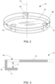
- the protective cover 70 is shown in accordance with one embodiment or aspect of the present disclosure.
- the protective cover 70 has a cover face 74 that is configured to cover the connection flange 60 and the access door 66.
- the cover face 74 is shaped to correspond to an outer shape of the connection flange 60. While the cover face 74 may be substantially planar, other non-planar shapes are also possible.
- a portion of an inner surface of the cover face 74 is configured to contact the annular seal 67 of the connection flange 60 when the protective cover 70 is connected to the connection flange 60. In this manner, a sealed connection can be made between the protective cover 70 and the connection flange 60.
- the protective cover 70 has an annular rim 76 protruding from the cover face 74.
- the annular rim 76 has a first portion that protrudes away from the cover face 74 in a direction that is substantially perpendicular to a plane defined by the cover face 74 and a second portion that protrudes in a direction toward a central axis 79 of the protective cover 70.
- the annular rim 76 may have an "L" shape, although other shapes of the annular rim 76 are not precluded.
- the annular rim 76 may have a first end 76a connected to the cover face 74 and a second free end 76b.
- the second free 76b end may have at least one locking tab 77 that protrudes toward the central axis 79 and is spaced apart from the cover face 74 by a distance X (shown in FIG. 3 ).
- the at least one locking tab 77 may be a plurality of locking tabs 77 spaced apart from each other around a perimeter of the cover face 74 about the central axis 79.
- the locking tabs 77 may have equal angular spacing from each other around a perimeter of the cover face 74.
- the locking tabs 77 may have unequal angular spacing therebetween.
- the annular rim 76 may be configured to interact with at least a portion of the connection flange 60 for removably securing the protective cover 70 to the connection flange 60.
- the annular rim 76 including the at least one locking tab 77, may be configured to interact with corresponding locking features on the connection flange 60 to removably secure the protective cover 70 to the connection flange 60.
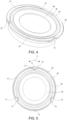
- connection flange 60 may have at least one radial recess 78 extending radially inward from a perimeter surface 80 of the connection flange 60.
- Each radial recess 78 may be shaped to correspond to a shape of the locking tab 77 on the protective cover 70.
- Each radial recess 78 is configured to receive the corresponding locking tab 77 when the protective cover 70 is aligned for connection with the connection flange 60.
- the number and spacing of the radial recesses 78 on the connection flange 60 corresponds to the number and spacing of the locking tabs 77 on the protective cover 70.
- the annular seal 67 is positioned radially inward of the perimeter surface 80 and protrudes distally thereto.
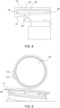
- the protective cover 70 is rotatable relative to the connection flange 60 about the central axis 79 between an unlocked position ( FIG. 5 ), in which each of locking tabs 77 is radially aligned with the radial recesses 78 such that the locking tab 77 is received with the at least one radial recess 78 to permit removal of the protective cover 70 from the connection flange 60, and a locked position ( FIG. 6 ), in which each of the locking tabs 77 is radially offset relative to the radial recesses 78 to prevent removal of the protective cover 70 from the connection flange 60.
- the protective cover 70 may be rotatable about the central axis 79 in a direction of arrow A (shown in FIG. 5 ).
- the protective cover 70 may be rotatable in a first (e.g., clockwise) direction or a second (e.g., counterclockwise) direction to either lock the protective cover 70 from the unlocked position to the locked position, or to unlock the protective cover 70 from the locked position to the unlocked position.
- the protective cover 70 may be rotatable in a single direction to lock the protective cover 70 and an opposite direction to unlock the protective cover 70.
- the protective cover 70 may be rotatable in a first direction to lock the protective cover 70 from the unlocked position to the locked position, and in a second direction opposite the first direction to unlock the protective cover 70 from the locked position to the unlocked position.
- rotation of the protective cover 70 to the locked position may position the locking tab 77 of each protrusion 76 under the connection flange 60 to prevent removal of the protective cover 70 from the connection flange 60.
- Distance X between the inner surface of the cover face 74 and the locking tab 77 may correspond to a thickness of the connection flange 70.
- the protective cover 70 has at least one rib 82 protruding from an inner surface 84 of the cover face 74 in a direction toward the connection flange 60 and the access door 66.
- the at least one rib 82 may be an annular structure that is aligned with the annular seal 67 on the connection flange 60. When the protective cover 70 is in the locked position, the at least one rib 82 is configured to exert a constant pressure on the annular seal 67 to seal the interface between the protective cover 70 and the connection flange 60.
- the protective cover 70 may optionally include at least one viewing window 88 over the at least one protrusion 76.
- the viewing window 88 may extend through the cover face 74 such that the at least a portion of the protrusion 76 may be visible through the viewing window 88.
- the viewing window 88 may be configured to permit confirmation of visual presence of the at least one radial recess 78 on the connection flange 70 when the protective cover 70 is in the unlocked position. In this manner, the viewing window helps with proper alignment of the protective cover 70 relative to the connection flange 60 during initial connection of the protective cover 70 to the connection flange 60.
- connection flange 60 and the protective cover 70 may have a lock indicator configured to indicate the locked position of the protective cover 70.
- the connection flange 60 may have a first lock indicator 90 and the protective cover 70 may have a second lock indicator 92.
- the first and second lock indicators 90, 92 may be dots, recesses, protrusions, or other structures on the connection flange 60 and the protective cover 70 that provide a visual indication of a rotational alignment between the connection flange 60 and the protective cover 70.
- the first lock indicator 90 and the second lock indicator 92 may be rotationally aligned only when the protective cover 70 is in the locked position with the connection flange 60.
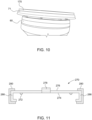
- a protective cover 170 is shown in accordance with another embodiment or aspect of the present disclosure.
- the connection flange 60 includes a perimeter lip 71
- the protective cover 170 has at least one clip 172 that is configured for removably connecting with the perimeter lip 71 of the connection flange 70.
- the at least one clip 172 may be a continuous clip that extends around an entire perimeter of the protective cover 170 to permit the protective cover 170 to snap over the perimeter lip 71.
- the at least one clip 172 may be a plurality of clips that are radially spaced from each other around a perimeter of the protective cover 170.
- a tab 174 may be provided on an outer portion of the protective cover 170 to facilitate with removal of the protective cover 170 from the connection flange 60.
- a protective cover 270 is shown in accordance with another embodiment or aspect of the present disclosure.
- the protective cover 270 has a seal 272 configured for engaging at least one of the connection flange 70 and the access door 66 (shown in FIG. 1 ).
- the seal 272 may be provided on an inner surface 274 of the cover face 276.
- the seal 272 may be an elastomeric O-ring.
- the protective cover 270 may have a pressure control device 278 configured for venting excess pressure in a direction from the interior cavity of the transfer bag 50 (shown in FIG. 1 ) to atmosphere.
- the pressure control device 278 may be a one-way valve.
- the protective cover 270 may have a tamper evident indicator 280.
- the tamper evident indicator 280 may be a tearable shrink sleeve or tab fitted around a perimeter of the protective cover 270, such as on at least one of the protrusions 286.
- the tamper evident indicator 280 may prevent removal of the protective cover 270 from the connection flange 70 prior to removal of the tamper evident indicator 280.
- a protective cover 370 is shown in accordance with additional embodiments or aspects of the present disclosure.
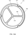
- the protective covers 370 shown in FIGS. 12A-12C may have the same features discussed herein with reference to the embodiments or aspects shown in FIGS. 2-11 .
- the protective covers 370 shown in FIGS. 12A-12C further include at least one reinforcement rib 380 extending across at least a portion of the cover face 374 and configured to increase the structural rigidity of the protective cover 370.
- the protective cover 370 may have 3, 4, 6, or any other number of reinforcement ribs 380 protruding radially inwardly from an outer rim 382 of the protective cover 370.
- the reinforcement ribs 380 may be spaced apart from each other around a perimeter of the cover face 374 about the central axis 379. In some embodiments or aspects, the reinforcement ribs 380 may have equal angular spacing from each other around a perimeter of the cover face 374. In other embodiments or aspects, the reinforcement ribs 380 may have unequal angular spacing therebetween. The reinforcement ribs 380 may be aligned with the locking tabs 377, such as by being positioned between the locking tabs 377 or in line with the locking tabs 377.
Landscapes
- Health & Medical Sciences (AREA)
- Engineering & Computer Science (AREA)
- Mechanical Engineering (AREA)
- Epidemiology (AREA)
- Life Sciences & Earth Sciences (AREA)
- Animal Behavior & Ethology (AREA)
- General Health & Medical Sciences (AREA)
- Public Health (AREA)
- Veterinary Medicine (AREA)
- Apparatus For Disinfection Or Sterilisation (AREA)
- Closures For Containers (AREA)
- Packages (AREA)
Priority Applications (4)
| Application Number | Priority Date | Filing Date | Title |
|---|---|---|---|
| EP23306439.3A EP4516257A1 (fr) | 2023-08-31 | 2023-08-31 | Récipient et couvercle de protection pour récipient de transfert de composants stérilisés |
| CN202480056134.7A CN121752214A (zh) | 2023-08-31 | 2024-08-28 | 用于转移无菌部件的容器的保护盖 |
| PCT/US2024/044094 WO2025049511A1 (fr) | 2023-08-31 | 2024-08-28 | Couvercle de protection pour récipient pour le transfert de composants stérilisés |
| MX2026001977A MX2026001977A (es) | 2023-08-31 | 2026-02-18 | Cubierta protectora para recipiente de transferencia de componentes esterilizados |
Applications Claiming Priority (1)
| Application Number | Priority Date | Filing Date | Title |
|---|---|---|---|
| EP23306439.3A EP4516257A1 (fr) | 2023-08-31 | 2023-08-31 | Récipient et couvercle de protection pour récipient de transfert de composants stérilisés |
Publications (1)
| Publication Number | Publication Date |
|---|---|
| EP4516257A1 true EP4516257A1 (fr) | 2025-03-05 |
Family
ID=88017760
Family Applications (1)
| Application Number | Title | Priority Date | Filing Date |
|---|---|---|---|
| EP23306439.3A Pending EP4516257A1 (fr) | 2023-08-31 | 2023-08-31 | Récipient et couvercle de protection pour récipient de transfert de composants stérilisés |
Country Status (4)
| Country | Link |
|---|---|
| EP (1) | EP4516257A1 (fr) |
| CN (1) | CN121752214A (fr) |
| MX (1) | MX2026001977A (fr) |
| WO (1) | WO2025049511A1 (fr) |
Citations (7)
| Publication number | Priority date | Publication date | Assignee | Title |
|---|---|---|---|---|
| US4445550A (en) * | 1982-08-20 | 1984-05-01 | Franrica Mfg. Inc. | Flexible walled container having membrane fitment for use with aseptic filling apparatus |
| US4557956A (en) * | 1982-12-23 | 1985-12-10 | Luwa Ag | Deformable container with filler unit |
| GB2494696A (en) * | 2011-09-17 | 2013-03-20 | Shafik Salih | Combination Lock Closure |
| US20130292380A1 (en) * | 2010-09-08 | 2013-11-07 | Ipn Ip B.V. | Closure Device |
| WO2022043638A1 (fr) * | 2020-08-27 | 2022-03-03 | Getinge Life Science France | Sac de transfert étanche présentant une résistance mécanique augmentée |
| WO2022263635A1 (fr) * | 2021-06-18 | 2022-12-22 | Becton Dickinson France | Tronc flexible et agencement de support rigide pour le transfert de constituants stériles à partir d'un contenant |
| US20230026497A1 (en) * | 2019-12-20 | 2023-01-26 | Abc Transfer | Container Having Reinforced Sealing Properties |
Family Cites Families (1)
| Publication number | Priority date | Publication date | Assignee | Title |
|---|---|---|---|---|
| WO2017135958A1 (fr) * | 2016-02-04 | 2017-08-10 | Silgan White Cap LLC | Ensemble récipient avec évent |
-
2023
- 2023-08-31 EP EP23306439.3A patent/EP4516257A1/fr active Pending
-
2024
- 2024-08-28 CN CN202480056134.7A patent/CN121752214A/zh active Pending
- 2024-08-28 WO PCT/US2024/044094 patent/WO2025049511A1/fr active Pending
-
2026
- 2026-02-18 MX MX2026001977A patent/MX2026001977A/es unknown
Patent Citations (8)
| Publication number | Priority date | Publication date | Assignee | Title |
|---|---|---|---|---|
| US4445550A (en) * | 1982-08-20 | 1984-05-01 | Franrica Mfg. Inc. | Flexible walled container having membrane fitment for use with aseptic filling apparatus |
| US4445550B1 (en) * | 1982-08-20 | 1999-03-09 | Scholle Corp | Flexible walled container having membrane fitment for use with aseptic filling apparatus |
| US4557956A (en) * | 1982-12-23 | 1985-12-10 | Luwa Ag | Deformable container with filler unit |
| US20130292380A1 (en) * | 2010-09-08 | 2013-11-07 | Ipn Ip B.V. | Closure Device |
| GB2494696A (en) * | 2011-09-17 | 2013-03-20 | Shafik Salih | Combination Lock Closure |
| US20230026497A1 (en) * | 2019-12-20 | 2023-01-26 | Abc Transfer | Container Having Reinforced Sealing Properties |
| WO2022043638A1 (fr) * | 2020-08-27 | 2022-03-03 | Getinge Life Science France | Sac de transfert étanche présentant une résistance mécanique augmentée |
| WO2022263635A1 (fr) * | 2021-06-18 | 2022-12-22 | Becton Dickinson France | Tronc flexible et agencement de support rigide pour le transfert de constituants stériles à partir d'un contenant |
Also Published As
| Publication number | Publication date |
|---|---|
| MX2026001977A (es) | 2026-04-01 |
| CN121752214A (zh) | 2026-03-27 |
| WO2025049511A1 (fr) | 2025-03-06 |
Similar Documents
| Publication | Publication Date | Title |
|---|---|---|
| KR970002588B1 (ko) | 신축자재성 주사기 | |
| EP2939649B1 (fr) | Cylindre extérieur de seringue pré-remplie et son conditionnement | |
| US8231585B2 (en) | Membrane syringe | |
| EP1339372B1 (fr) | Adaptateur d'acces a la fiole a activation axiale | |
| ES2901135T3 (es) | Conjunto de bolsa con tapón | |
| US20130165851A1 (en) | Tube with a female luer lock fitting | |
| EP2934420B1 (fr) | Emballage primaire pour le stockage et/ou l'administration de composés pharmaceutiques ou médicaux | |
| US20250017819A1 (en) | Medicament container | |
| JPH0554791B2 (fr) | ||
| US11338088B2 (en) | Venting safety closure | |
| US20230248897A1 (en) | Impact resistant and tamper evident system for prefilled syringe | |
| KR102079412B1 (ko) | 컨테이너용 폐쇄 시스템 | |
| JPH0554792B2 (fr) | ||
| US12533669B2 (en) | Flexible trunk and rigid support arrangement for the transfer of sterile components from a container | |
| JP7386579B2 (ja) | プラスチック製アダプタ及び閉鎖式薬物搬送システム | |
| EP4516257A1 (fr) | Récipient et couvercle de protection pour récipient de transfert de composants stérilisés | |
| US11034491B2 (en) | Sealing cap for a container for holding a medical liquid | |
| EP0591156B1 (fr) | Flacon a dosage unitaire | |
| HK1001552B (en) | Unit dose container | |
| CN1223329C (zh) | 对医用容器的改进 | |
| WO2010089388A1 (fr) | Enceinte de confinement pour bouteilles, flacons et autres récipients | |
| EP4520362A1 (fr) | Couvre-porte stérile pour transfert de bouchon médical | |
| EP4595986A1 (fr) | Couvercle de protection pour récipient de transfert de composants stérilisés | |
| WO2026090494A1 (fr) | Améliorations apportées ou se rapportant à des guides de seringue pour récipients de médicament | |
| HK1028872A (en) | Improvements related to medical containers |
Legal Events
| Date | Code | Title | Description |
|---|---|---|---|
| PUAI | Public reference made under article 153(3) epc to a published international application that has entered the european phase |
Free format text: ORIGINAL CODE: 0009012 |
|
| STAA | Information on the status of an ep patent application or granted ep patent |
Free format text: STATUS: THE APPLICATION HAS BEEN PUBLISHED |
|
| AK | Designated contracting states |
Kind code of ref document: A1 Designated state(s): AL AT BE BG CH CY CZ DE DK EE ES FI FR GB GR HR HU IE IS IT LI LT LU LV MC ME MK MT NL NO PL PT RO RS SE SI SK SM TR |
|
| STAA | Information on the status of an ep patent application or granted ep patent |
Free format text: STATUS: REQUEST FOR EXAMINATION WAS MADE |
|
| 17P | Request for examination filed |
Effective date: 20250902 |