EP4516435A1 - Direktantriebsspindel mit heckmotor - Google Patents
Direktantriebsspindel mit heckmotor Download PDFInfo
- Publication number
- EP4516435A1 EP4516435A1 EP22939914.2A EP22939914A EP4516435A1 EP 4516435 A1 EP4516435 A1 EP 4516435A1 EP 22939914 A EP22939914 A EP 22939914A EP 4516435 A1 EP4516435 A1 EP 4516435A1
- Authority
- EP
- European Patent Office
- Prior art keywords
- mandrel
- bearing
- motor
- balance
- disc
- Prior art date
- Legal status (The legal status is an assumption and is not a legal conclusion. Google has not performed a legal analysis and makes no representation as to the accuracy of the status listed.)
- Pending
Links
Images




Classifications
-
- B—PERFORMING OPERATIONS; TRANSPORTING
- B23—MACHINE TOOLS; METAL-WORKING NOT OTHERWISE PROVIDED FOR
- B23Q—DETAILS, COMPONENTS, OR ACCESSORIES FOR MACHINE TOOLS, e.g. ARRANGEMENTS FOR COPYING OR CONTROLLING; MACHINE TOOLS IN GENERAL CHARACTERISED BY THE CONSTRUCTION OF PARTICULAR DETAILS OR COMPONENTS; COMBINATIONS OR ASSOCIATIONS OF METAL-WORKING MACHINES, NOT DIRECTED TO A PARTICULAR RESULT
- B23Q1/00—Members which are comprised in the general build-up of a form of machine, particularly relatively large fixed members
- B23Q1/70—Stationary or movable members for carrying working-spindles for attachment of tools or work
-
- B—PERFORMING OPERATIONS; TRANSPORTING
- B23—MACHINE TOOLS; METAL-WORKING NOT OTHERWISE PROVIDED FOR
- B23Q—DETAILS, COMPONENTS, OR ACCESSORIES FOR MACHINE TOOLS, e.g. ARRANGEMENTS FOR COPYING OR CONTROLLING; MACHINE TOOLS IN GENERAL CHARACTERISED BY THE CONSTRUCTION OF PARTICULAR DETAILS OR COMPONENTS; COMBINATIONS OR ASSOCIATIONS OF METAL-WORKING MACHINES, NOT DIRECTED TO A PARTICULAR RESULT
- B23Q5/00—Driving or feeding mechanisms; Control arrangements therefor
- B23Q5/02—Driving main working members
- B23Q5/04—Driving main working members rotary shafts, e.g. working-spindles
- B23Q5/10—Driving main working members rotary shafts, e.g. working-spindles driven essentially by electrical means
-
- B—PERFORMING OPERATIONS; TRANSPORTING
- B23—MACHINE TOOLS; METAL-WORKING NOT OTHERWISE PROVIDED FOR
- B23Q—DETAILS, COMPONENTS, OR ACCESSORIES FOR MACHINE TOOLS, e.g. ARRANGEMENTS FOR COPYING OR CONTROLLING; MACHINE TOOLS IN GENERAL CHARACTERISED BY THE CONSTRUCTION OF PARTICULAR DETAILS OR COMPONENTS; COMBINATIONS OR ASSOCIATIONS OF METAL-WORKING MACHINES, NOT DIRECTED TO A PARTICULAR RESULT
- B23Q11/00—Accessories fitted to machine tools for keeping tools or parts of the machine in good working condition or for cooling work; Safety devices specially combined with or arranged in, or specially adapted for use in connection with, machine tools
- B23Q11/12—Arrangements for cooling or lubricating parts of the machine
- B23Q11/126—Arrangements for cooling or lubricating parts of the machine for cooling only
- B23Q11/127—Arrangements for cooling or lubricating parts of the machine for cooling only for cooling motors or spindles
-
- B—PERFORMING OPERATIONS; TRANSPORTING
- B23—MACHINE TOOLS; METAL-WORKING NOT OTHERWISE PROVIDED FOR
- B23Q—DETAILS, COMPONENTS, OR ACCESSORIES FOR MACHINE TOOLS, e.g. ARRANGEMENTS FOR COPYING OR CONTROLLING; MACHINE TOOLS IN GENERAL CHARACTERISED BY THE CONSTRUCTION OF PARTICULAR DETAILS OR COMPONENTS; COMBINATIONS OR ASSOCIATIONS OF METAL-WORKING MACHINES, NOT DIRECTED TO A PARTICULAR RESULT
- B23Q5/00—Driving or feeding mechanisms; Control arrangements therefor
- B23Q5/02—Driving main working members
- B23Q5/04—Driving main working members rotary shafts, e.g. working-spindles
- B23Q5/12—Mechanical drives with means for varying the speed ratio
Definitions
- the present invention relates to the technical field of machining tools, specifically a motor rear-mounted direct drive spindle.
- An electric spindle is an electromechanical functional component that integrates a spindle motor inside to achieve power conversion and output. It is characterized by its compact structure and suitability for high-speed cutting operations.
- a built-in motor of the electric spindle is mounted between two sets of supporting bearing components.
- the heat generated by the stator and rotor of the built-in motor significantly impacts the bearings and the output end of the electric spindle, deteriorating the working conditions of the output end bearings, causing poor heat dissipation of the mandrel, and leading to large thermal elongation of the spindle.
- the present invention discloses a motor rear-mounted direct drive spindle, where a motor with the motor rear-mounted spindle is entirely exposed outside, thus distancing the motor from a mandrel, improving heat dissipation, and reducing thermal elongation of a spindle.
- a motor rear-mounted direct drive spindle including: a spindle housing; a mandrel that is rotatably disposed within the spindle housing; a bearing; and a torque motor, wherein the bearing includes a first bearing and a second bearing that provide radial and axial support to the mandrel, the first bearing and the second bearing are disposed inside the spindle housing, one end of the mandrel extends outside the spindle housing, the torque motor and the spindle housing are axially aligned, the torque motor includes a rotor and a stator, the end of the mandrel located outside the spindle housing is inserted into and connected to an end of the rotor, and the rotor is fixedly connected to the mandrel.
- the bearing includes a first bearing and a second bearing that provide radial and axial support to the mandrel, the first bearing and the second bearing are disposed inside the spindle housing, one end of the mandrel extends outside the spind
- the rotor is provided with a connecting disc in a radial direction, a connecting bolt is provided on the connecting disc, and when an end face of the mandrel contacts the connecting disc, the connecting bolt connects the mandrel and the connecting disc.
- a heat insulation ring or a labyrinth structure is provided between the torque motor and the spindle housing.
- the labyrinth structure is arranged on a side of the heat insulation ring facing the torque motor.
- one end of the rotor away from the mandrel is provided with a brake disc and a plurality of clamps which are arranged in a multipoint symmetric pattern along a circumferential direction of the brake disc.
- the brake disc is made of a special steel and has a thickness of 1 mm, forming a brake disc structure with a certain deformation capability.
- a dynamic balance probe is provided at one end of the spindle housing away from the torque motor, the dynamic balance probe can detect an imbalance amount of the mandrel after mounting a workpiece, and an adjustment mechanism which is capable of adjusting a dynamic balance according to a measurement result of the dynamic balance probe is provided at the end of the mandrel.
- the adjustment mechanism includes a balance disc and a plurality of balance adjustment blocks which are slidingly connected to the balance disc respectively, a set screw is provided between the balance adjustment blocks and the balance disc, and the set screw is threadedly connected to the balance adjustment blocks.
- the balance disc is provided with a scale, and the balance adjustment blocks are provided with indicating arrows.
- an annular sliding groove is provided on the balance disc, an inner diameter of the sliding groove gradually increases from an opening end of the sliding groove to a bottom wall of the sliding groove, and the balance adjustment blocks are trapezoidal.
- a cooling water channel for cooling the first bearing is provided on the spindle housing.
- a motor rear-mounted direct drive spindle which is mounted on a numerical control machine tool, as shown in Fig. 1 , includes a torque motor 1 and a spindle housing 2 arranged axially side by side.
- the spindle housing 2 has an installation cavity on a side facing the torque motor 1.
- An end of the torque motor 1 is inserted into and connected to the spindle housing 2, and the torque motor 1 and spindle housing 2 are connected together by screws, forming a main motor rear-mounted structure, reducing the mutual thermal impact between the motor and bearings.
- the torque motor 1 is entirely exposed outside the spindle housing 2, ensuring the heat dissipation of the torque motor 1.
- the torque motor 1 has the advantages of small axial size, low inertia, light weight, rapid response, and low transmitted noise and vibration, ensuring the overall volume after assembly is relatively small.
- the spindle housing 2 is a fully enclosed cylinder, the spindle housing 2 has a circular through hole along its axis, a mandrel 3 is mounted at the circular through hole of the spindle housing 2, and an end of the mandrel 3 close to the torque motor 1 extends outside the spindle housing 2 and connects to the torque motor 1, enabling the torque motor 1 to drive the mandrel 3 to rotate when the torque motor 1 is started.
- bearings are mounted inside the spindle housing 2.
- the bearings include a first bearing 41 and a second bearing 42 that provide radial and axial support to the mandrel 3.
- the first bearing 41 is mounted at an end of the mandrel 3 away from the torque motor 1, while the second bearing 42 is mounted at an end of the mandrel 3 close to the torque motor 1.
- the rotation of the mandrel 3 relative to the spindle housing 2 is implemented through the cooperation of the first bearing 41 and the second bearing 42.
- the two axial sides of the first bearing 41 and the two axial sides of the second bearing 42 are respectively provided with an inner spacer sleeve 51 and an outer spacer sleeve 52.
- the inner spacer sleeve 51 of the first bearing 41 and the outer spacer sleeve 52 of the second bearing 42 are of an integrated structure. Under the action of the inner spacer 51 and the outer spacer sleeve 52, the positions of the bearings are restricted.
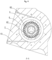
- the spindle housing 2 is provided with a cooling water channel 6 that can cool the second bearing 42.
- the cooling water channel 6 is annularly arranged and surrounds the second bearing 42.
- the cooling water channel 6 includes an water inlet channel 61 and an water outlet channel 62.
- the water inlet channel 61 and the water outlet channel 62 are respectively located on the lower and upper sides of the spindle housing 2.
- the water inlet channel 61 is positioned below the spindle housing 2, while the water outlet channel 62 is positioned above the spindle housing 2.
- Both the water inlet channel 61 and the water outlet channel 62 are arranged in an inclined manner, enabling the cooling of the second bearing 42 and thereby reducing the thermal elongation of the mandrel 3.
- the torque motor 1 includes a rotor 11, a stator 12, and a casing 13.
- the stator 12 is fixedly connected to the casing 13.
- the rotor 11 has an insertion cavity in the axial direction.
- the end of the mandrel 3 is inserted into and connected to the insertion cavity.
- the rotor 11 has an annular connecting disc 71 extending inwardly in the radial direction of the rotor 11.
- the end face of the connecting disc 71 is flush with the end face of the mandrel 3.
- the connecting disc 71 is provided with a plurality of connecting bolts 72, which are arranged along the circumferential direction of the connecting disc 71 at equal intervals.
- a brake disc 81 is fixedly provided on a side of the torque motor 1 away from the spindle housing 2.
- the brake disc 81 is an annular disc-shaped structure made of special steel.
- the thickness of the brake disc 81 is preferably 1 mm, and thereby, a structure of the brake disc 81 having a certain deformation capability is constituted such that the brake disc 81 is an elastomer.
- An end of the rotor 11 away from the mandrel 3 is fixedly provided with a mounting flange 111 and an encoder.
- the encoder is fixedly provided at the end of the rotor 11 through an encoder flange 112.
- the brake disc 81 and the mounting flange 111 are connected together by screws, making the brake disc 81 and the rotor 11 integrally rigidly connected.
- a plurality of clamps 82 is arranged in a circumferential direction of the brake disc 81, and the clamps 82 are arranged in a multipoint symmetric pattern along the circumferential direction of the brake disc 81.
- Each pair of clamps 82 forms a group, and a plurality of groups of clamps 82 is arranged in the circumferential direction of the brake disc 81.
- the two clamps 82 in the same group are symmetrically arranged with respect to the center of the brake disc 81.
- the clamps 82 are preferably high-precision clamps 82, and more preferably hydraulic clamps 82.
- the torque motor 1 is also provided with a cooling water system 9 that can cool the stator 12.
- the cooling water system 9 includes a water-cooling joint 91 and a water-cooling pipeline. A cooling liquid is introduced into the water-cooling pipeline through the water-cooling joint 91 to cool the stator 12.
- annular heat insulation ring 10 is arranged between the torque motor 1 and the spindle housing 2, with the heat insulation ring 10 being connected to the spindle housing 2 by screws.
- a side of the heat insulation ring 10 facing the torque motor 1 is provided with a labyrinth structure 101, which consists of a plurality of annular grooves arranged in a spiral pattern. These annular grooves are concentrically arranged, making it difficult for the heat generated by the torque motor 1 to transfer to the spindle housing 2, further reducing the thermal impact between the motor and the bearings.
- a dynamic balance probe 20 and an adjustment mechanism 30 are arranged on a side of the spindle housing 2 away from the torque motor 1.
- the dynamic balance probe 20 is preferably a high-precision dynamic balance detector for machine tools, featuring functions such as harmonic vibration analysis.
- the dynamic balance probe 20 can perform real-time analysis of unbalanced vibrations of the mandrel 3 and detect an imbalance amount of the mandrel 3 after a workpiece is mounted.
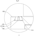
- the adjustment mechanism 30 includes a circular balance disc 301 and balance adjustment blocks 302.
- the balance disc 301 can adjust the dynamic balance according to the measurement results of the dynamic balance probe 20.
- the balance disc 301 is in an annular disc shape, parallel to the brake disc 81, and connected to the mandrel 3 by screws.
- an annular sliding groove 3011 is provided on a side of the balance disc 301 facing away from the spindle housing 2.
- the sliding groove 3011 is arranged at an edge of the balance disc 301, and the inner diameter of the sliding groove 3011 gradually increases from an opening end of the sliding groove 3011 to a bottom wall of the sliding groove 3011.
- the axial section of the sliding groove 3011 is trapezoidal.
- a plurality of balance adjustment blocks 302 is arranged along the circumferential direction of the balance disc 301 at equal intervals, allowing for the balancing of different workpiece eccentricities.
- the balance adjustment blocks 302 are arranged in a trapezoidal shape and embedded in the sliding groove 3011, such that the balance adjustment blocks 302 and the sliding groove 3011 form a dovetail joint.
- the balance adjustment blocks 302 are slidably connected to the balance disc 301. By adjusting the positions of different balance adjustment blocks 302 on the balance disc 301, the center of gravity of the balance disc 301 can be adjusted.
- threaded holes are provided on the balance adjustment blocks 302, and set screws 303 are inserted through the threaded holes.
- the set screws 303 are threadedly connected to the balance adjustment blocks 302, with the ends of the set screws 303 passing through the balance adjustment blocks 302 and contacting the bottom wall of the sliding groove 3011.
- the edge of the balance disc 301 is provided with a scale 3012, and the balance adjustment blocks 302 are provided with arrows that can indicate the scale 3012.
- the arrows are located at the centers of the balance adjustment blocks 302.
- the eccentricity of the workpiece weight causes vibrations in the mandrel 3, making it difficult for the mandrel 3 to reach a high rotational speed and causing significant damage to the bearings of the mandrel 3.
- the balance adjustment blocks 302 can be locked with set screws 303, making installation convenient. The higher the rotational speed of the mandrel 3, the more tightly the balance adjustment blocks 302 adhere due to centrifugal force.
- the working principle of this application is as follows.
- the motor is rear-mounted, exposing the entire torque motor 1 outside the spindle housing 2 and forming a main motor rear-mounted structure. This structure reduces the mutual thermal impact between the motor and the bearings.
- One end of the mandrel 3 close to the torque motor 1 extends outside the spindle housing 2 and is connected to the torque motor 1. While achieving the rotational drive of the mandrel 3, the torque motor 1 and the mandrel 3 are separated from each other.
Landscapes
- Engineering & Computer Science (AREA)
- Mechanical Engineering (AREA)
- Connection Of Motors, Electrical Generators, Mechanical Devices, And The Like (AREA)
- Motor Or Generator Frames (AREA)
- Turning (AREA)
Applications Claiming Priority (2)
| Application Number | Priority Date | Filing Date | Title |
|---|---|---|---|
| CN202210451054.4A CN114682807B (zh) | 2022-04-26 | 2022-04-26 | 一种电机后置直驱主轴 |
| PCT/CN2022/136821 WO2023207100A1 (zh) | 2022-04-26 | 2022-12-06 | 一种电机后置直驱主轴 |
Publications (2)
| Publication Number | Publication Date |
|---|---|
| EP4516435A1 true EP4516435A1 (de) | 2025-03-05 |
| EP4516435A4 EP4516435A4 (de) | 2025-12-17 |
Family
ID=82144321
Family Applications (1)
| Application Number | Title | Priority Date | Filing Date |
|---|---|---|---|
| EP22939914.2A Pending EP4516435A4 (de) | 2022-04-26 | 2022-12-06 | Direktantriebsspindel mit heckmotor |
Country Status (6)
| Country | Link |
|---|---|
| US (1) | US20250262703A1 (de) |
| EP (1) | EP4516435A4 (de) |
| JP (1) | JP7811660B2 (de) |
| KR (1) | KR20240158929A (de) |
| CN (1) | CN114682807B (de) |
| WO (1) | WO2023207100A1 (de) |
Families Citing this family (4)
| Publication number | Priority date | Publication date | Assignee | Title |
|---|---|---|---|---|
| CN114682807B (zh) * | 2022-04-26 | 2026-02-03 | 科德数控股份有限公司 | 一种电机后置直驱主轴 |
| CN117564307B (zh) * | 2024-01-19 | 2024-04-05 | 山东豪迈数控机床有限公司 | 一种主轴管路连接结构及机床 |
| CN117798714A (zh) * | 2024-02-19 | 2024-04-02 | 东莞市成泰伺服技术有限公司 | 一种多功能机械加工动力机构 |
| CN119036155B (zh) * | 2024-10-31 | 2025-02-07 | 福建合盈机械有限公司 | 一种车床主轴刹停装置 |
Family Cites Families (27)
| Publication number | Priority date | Publication date | Assignee | Title |
|---|---|---|---|---|
| CN1295488C (zh) * | 2003-06-14 | 2007-01-17 | 重庆大学 | 平衡盘及数字校正方法 |
| JP4719596B2 (ja) * | 2006-03-14 | 2011-07-06 | 西部電機株式会社 | 工作機械の主軸台装置 |
| CN201623579U (zh) * | 2009-11-27 | 2010-11-03 | 江苏华雕机械有限公司 | 电机后置式电主轴 |
| KR101503010B1 (ko) * | 2013-09-11 | 2015-03-16 | 주식회사 에스엠에스비 | 고속 고주파 스핀들 |
| CN103567468B (zh) * | 2013-09-16 | 2016-08-24 | 浙江日发精密机械股份有限公司 | 数控车床双通道水冷电主轴 |
| CN103567809B (zh) * | 2013-10-16 | 2016-06-08 | 杨孝晟 | 动平衡结构 |
| CN204477314U (zh) * | 2014-11-24 | 2015-07-15 | 上海师范大学 | 一种迷宫式隔热轴封装置 |
| JP5943116B2 (ja) * | 2015-04-07 | 2016-06-29 | 日本精工株式会社 | モータビルトイン方式の主軸装置 |
| CN106041635B (zh) * | 2016-07-22 | 2018-01-05 | 宁波海天精工股份有限公司 | 一种电主轴轴承座的隔热冷却机构 |
| CN206060487U (zh) * | 2016-10-09 | 2017-03-29 | 西门子电气传动有限公司 | 动平衡环、动平衡调节装置 |
| CN206614041U (zh) * | 2017-03-15 | 2017-11-07 | 东莞百锐数控机床有限公司 | 一种车铣复合电主轴 |
| CN107900383B (zh) * | 2017-12-26 | 2024-01-30 | 广东圣特斯数控设备有限公司 | 一种数控机床的电主轴 |
| CN108817421A (zh) * | 2018-07-30 | 2018-11-16 | 东莞市显隆电机有限公司 | 一种高精度低能耗的高速气浮式电主轴 |
| CN109482911B (zh) * | 2018-11-21 | 2020-05-12 | 上海机床厂有限公司 | 高速静压后置式电主轴及动平衡方法 |
| CN110142644A (zh) * | 2019-05-31 | 2019-08-20 | 东莞市乔锋机械有限公司 | 一种加工中心主轴电机冷却隔离装置 |
| CN111331158B (zh) * | 2020-03-02 | 2024-10-18 | 芜湖美杰特数控科技有限公司 | 高速心轴内冷动静油压永磁伺服电主轴 |
| CN111300226A (zh) * | 2020-03-30 | 2020-06-19 | 芜湖美杰特数控科技有限公司 | 六轴数控内外圆复合磨床 |
| CN111482786A (zh) * | 2020-04-29 | 2020-08-04 | 科德数控股份有限公司 | 一种电机可扩展的动力机构后置式主轴 |
| CN112171350B (zh) * | 2020-09-03 | 2025-01-28 | 宁波海天精工股份有限公司 | 一种立式加工中心用b轴摆头 |
| CN213998466U (zh) * | 2020-11-26 | 2021-08-20 | 广州市昊志机电股份有限公司 | 一种电机后置主轴和机床 |
| CN214212233U (zh) * | 2020-12-04 | 2021-09-17 | 沈阳机床股份有限公司 | 一种倒立式车床的主轴结构 |
| CN112757025B (zh) * | 2021-01-27 | 2022-02-11 | 玉环图远机电有限公司 | 一种机床多头动力装置 |
| CN112846256A (zh) * | 2021-02-20 | 2021-05-28 | 广州市昊志机电股份有限公司 | 一种重载电主轴和机床 |
| CN216066988U (zh) * | 2021-11-23 | 2022-03-18 | 安阳莱工科技有限公司 | 一种永磁同步电主轴的双平衡装置 |
| CN114147627A (zh) * | 2021-12-14 | 2022-03-08 | 湖大海捷(湖南)工程技术研究有限公司 | 磨床液压浮动卡盘头架 |
| CN217315900U (zh) * | 2022-04-26 | 2022-08-30 | 科德数控股份有限公司 | 一种电机后置直驱主轴 |
| CN114682807B (zh) * | 2022-04-26 | 2026-02-03 | 科德数控股份有限公司 | 一种电机后置直驱主轴 |
-
2022
- 2022-04-26 CN CN202210451054.4A patent/CN114682807B/zh active Active
- 2022-12-06 KR KR1020247032366A patent/KR20240158929A/ko active Pending
- 2022-12-06 JP JP2024556561A patent/JP7811660B2/ja active Active
- 2022-12-06 WO PCT/CN2022/136821 patent/WO2023207100A1/zh not_active Ceased
- 2022-12-06 EP EP22939914.2A patent/EP4516435A4/de active Pending
- 2022-12-06 US US18/857,914 patent/US20250262703A1/en active Pending
Also Published As
| Publication number | Publication date |
|---|---|
| WO2023207100A1 (zh) | 2023-11-02 |
| CN114682807A (zh) | 2022-07-01 |
| EP4516435A4 (de) | 2025-12-17 |
| CN114682807B (zh) | 2026-02-03 |
| US20250262703A1 (en) | 2025-08-21 |
| JP2025511602A (ja) | 2025-04-16 |
| JP7811660B2 (ja) | 2026-02-05 |
| KR20240158929A (ko) | 2024-11-05 |
Similar Documents
| Publication | Publication Date | Title |
|---|---|---|
| US20250262703A1 (en) | Direct drive spindle having rear motor | |
| CN106984836B (zh) | 一种高速高精度内置式动静压电主轴 | |
| US5235228A (en) | Motor balancing structure | |
| KR20100100829A (ko) | 공작기계용 회전 분할 테이블 장치 | |
| CN100443258C (zh) | 换位工作台 | |
| CN112025335A (zh) | 一种超精密液压伺服转台 | |
| CN105108180A (zh) | 一种数控车床电主轴结构 | |
| CN109482911B (zh) | 高速静压后置式电主轴及动平衡方法 | |
| CN105598732B (zh) | 一种电动直线进给单元及其装配方法 | |
| CN219151585U (zh) | 一种油雾润滑的高速滚珠电主轴 | |
| CN201988725U (zh) | 一种气浮高速电主轴 | |
| CN217315900U (zh) | 一种电机后置直驱主轴 | |
| CN111408773B (zh) | 一种倾角偏心复合铣孔装置及工作方法 | |
| CN219562235U (zh) | 一种用于加工偏心瓦块的夹具 | |
| RU2854598C2 (ru) | Шпиндельный узел с прямым приводом от моментного двигателя | |
| WO2020125061A1 (zh) | 电主轴和电机 | |
| CN110594379B (zh) | 一种螺母驱动型液体静压丝杠螺旋传动副及机床 | |
| CN103586759B (zh) | 一种超高速磨削装备 | |
| CN111633558B (zh) | 一种棒料加工工作头 | |
| JP2007245255A (ja) | 工作機械の主軸台装置 | |
| CN118748485A (zh) | 一种高速高精度主轴电机 | |
| CN113752048B (zh) | 加工异形零件的动平衡调节工装 | |
| CN213701790U (zh) | 一种便于实现二次动平衡的高速主轴 | |
| CN214661529U (zh) | 一种新型重载静压主轴结构 | |
| CN110116370B (zh) | 静压型高精度回转分度装置 |
Legal Events
| Date | Code | Title | Description |
|---|---|---|---|
| STAA | Information on the status of an ep patent application or granted ep patent |
Free format text: STATUS: THE INTERNATIONAL PUBLICATION HAS BEEN MADE |
|
| PUAI | Public reference made under article 153(3) epc to a published international application that has entered the european phase |
Free format text: ORIGINAL CODE: 0009012 |
|
| STAA | Information on the status of an ep patent application or granted ep patent |
Free format text: STATUS: REQUEST FOR EXAMINATION WAS MADE |
|
| 17P | Request for examination filed |
Effective date: 20241126 |
|
| AK | Designated contracting states |
Kind code of ref document: A1 Designated state(s): AL AT BE BG CH CY CZ DE DK EE ES FI FR GB GR HR HU IE IS IT LI LT LU LV MC ME MK MT NL NO PL PT RO RS SE SI SK SM TR |
|
| DAV | Request for validation of the european patent (deleted) | ||
| DAX | Request for extension of the european patent (deleted) | ||
| RIC1 | Information provided on ipc code assigned before grant |
Ipc: B23B 19/02 20060101AFI20250703BHEP Ipc: B23Q 11/12 20060101ALI20250703BHEP Ipc: B23Q 1/70 20060101ALI20250703BHEP |
|
| A4 | Supplementary search report drawn up and despatched |
Effective date: 20251113 |
|
| RIC1 | Information provided on ipc code assigned before grant |
Ipc: B23B 19/02 20060101AFI20251107BHEP Ipc: B23Q 11/12 20060101ALI20251107BHEP Ipc: B23Q 1/70 20060101ALI20251107BHEP |