EP4516510A1 - Dispositif et procédé de traitement d'étiquettes - Google Patents
Dispositif et procédé de traitement d'étiquettes Download PDFInfo
- Publication number
- EP4516510A1 EP4516510A1 EP24197999.6A EP24197999A EP4516510A1 EP 4516510 A1 EP4516510 A1 EP 4516510A1 EP 24197999 A EP24197999 A EP 24197999A EP 4516510 A1 EP4516510 A1 EP 4516510A1
- Authority
- EP
- European Patent Office
- Prior art keywords
- head
- module
- plate
- immovable
- main shafts
- Prior art date
- Legal status (The legal status is an assumption and is not a legal conclusion. Google has not performed a legal analysis and makes no representation as to the accuracy of the status listed.)
- Pending
Links
Images


Classifications
-
- B—PERFORMING OPERATIONS; TRANSPORTING
- B31—MAKING ARTICLES OF PAPER, CARDBOARD OR MATERIAL WORKED IN A MANNER ANALOGOUS TO PAPER; WORKING PAPER, CARDBOARD OR MATERIAL WORKED IN A MANNER ANALOGOUS TO PAPER
- B31D—MAKING ARTICLES OF PAPER, CARDBOARD OR MATERIAL WORKED IN A MANNER ANALOGOUS TO PAPER, NOT PROVIDED FOR IN SUBCLASSES B31B OR B31C
- B31D1/00—Multiple-step processes for making flat articles ; Making flat articles
- B31D1/02—Multiple-step processes for making flat articles ; Making flat articles the articles being labels or tags
- B31D1/027—Multiple-step processes for making flat articles ; Making flat articles the articles being labels or tags involving, marking, printing or coding
-
- B—PERFORMING OPERATIONS; TRANSPORTING
- B65—CONVEYING; PACKING; STORING; HANDLING THIN OR FILAMENTARY MATERIAL
- B65C—LABELLING OR TAGGING MACHINES, APPARATUS, OR PROCESSES
- B65C9/00—Details of labelling machines or apparatus
-
- B—PERFORMING OPERATIONS; TRANSPORTING
- B31—MAKING ARTICLES OF PAPER, CARDBOARD OR MATERIAL WORKED IN A MANNER ANALOGOUS TO PAPER; WORKING PAPER, CARDBOARD OR MATERIAL WORKED IN A MANNER ANALOGOUS TO PAPER
- B31D—MAKING ARTICLES OF PAPER, CARDBOARD OR MATERIAL WORKED IN A MANNER ANALOGOUS TO PAPER, NOT PROVIDED FOR IN SUBCLASSES B31B OR B31C
- B31D1/00—Multiple-step processes for making flat articles ; Making flat articles
- B31D1/02—Multiple-step processes for making flat articles ; Making flat articles the articles being labels or tags
-
- B—PERFORMING OPERATIONS; TRANSPORTING
- B41—PRINTING; LINING MACHINES; TYPEWRITERS; STAMPS
- B41F—PRINTING MACHINES OR PRESSES
- B41F16/00—Transfer printing apparatus
- B41F16/0006—Transfer printing apparatus for printing from an inked or preprinted foil or band
- B41F16/002—Presses of the rotary type
- B41F16/0026—Presses of the rotary type with means for applying print under heat and pressure, e.g. using heat activable adhesive
-
- B—PERFORMING OPERATIONS; TRANSPORTING
- B41—PRINTING; LINING MACHINES; TYPEWRITERS; STAMPS
- B41F—PRINTING MACHINES OR PRESSES
- B41F16/00—Transfer printing apparatus
- B41F16/0006—Transfer printing apparatus for printing from an inked or preprinted foil or band
- B41F16/004—Presses of the reciprocating type
- B41F16/0046—Presses of the reciprocating type with means for applying print under heat and pressure, e.g. using heat activable adhesive
-
- B—PERFORMING OPERATIONS; TRANSPORTING
- B65—CONVEYING; PACKING; STORING; HANDLING THIN OR FILAMENTARY MATERIAL
- B65C—LABELLING OR TAGGING MACHINES, APPARATUS, OR PROCESSES
- B65C11/00—Manually-controlled or manually-operable label dispensers, e.g. modified for the application of labels to articles
-
- G—PHYSICS
- G09—EDUCATION; CRYPTOGRAPHY; DISPLAY; ADVERTISING; SEALS
- G09F—DISPLAYING; ADVERTISING; SIGNS; LABELS OR NAME-PLATES; SEALS
- G09F3/00—Labels, tag tickets, or similar identification or indication means; Seals; Postage or like stamps
-
- B—PERFORMING OPERATIONS; TRANSPORTING
- B41—PRINTING; LINING MACHINES; TYPEWRITERS; STAMPS
- B41P—INDEXING SCHEME RELATING TO PRINTING, LINING MACHINES, TYPEWRITERS, AND TO STAMPS
- B41P2219/00—Printing presses using a heated printing foil
- B41P2219/40—Material or products to be decorated or printed
-
- B—PERFORMING OPERATIONS; TRANSPORTING
- B44—DECORATIVE ARTS
- B44B—MACHINES, APPARATUS OR TOOLS FOR ARTISTIC WORK, e.g. FOR SCULPTURING, GUILLOCHING, CARVING, BRANDING, INLAYING
- B44B5/00—Machines or apparatus for embossing decorations or marks, e.g. embossing coins
- B44B5/0071—Machines or apparatus for embossing decorations or marks, e.g. embossing coins which simultaneously apply a decorative material
-
- B—PERFORMING OPERATIONS; TRANSPORTING
- B44—DECORATIVE ARTS
- B44B—MACHINES, APPARATUS OR TOOLS FOR ARTISTIC WORK, e.g. FOR SCULPTURING, GUILLOCHING, CARVING, BRANDING, INLAYING
- B44B5/00—Machines or apparatus for embossing decorations or marks, e.g. embossing coins
- B44B5/02—Dies; Accessories
- B44B5/028—Heated dies
Definitions
- the subject-matter of the invention is a device and method for label processing, in particular being a module for hot stamping and decorating labels.
- the field of the invention relates to the automation of production processes.
- Hot stamping modules are designed to improve the quality and aesthetics of labels by applying metallised foil to their surface. They are mainly used in the printing industry to produce labels for products such as packagings, food products, cosmetics and chemicals.
- EP3150367 discloses an invention being an apparatus for processing a flexible material, such as a paper material or a polymer film, in particular in the form of a continuous strip.
- the apparatus of that invention can be used as a cutting apparatus, in particular for obtaining labels destined to be applied on containers, such as bottles, jars, trays or others besides, to be used in the food, cosmetic sector or the like.
- the apparatus makes it possible to regulate the relative position of the first roller and the second roller, independently of the pressure with which the rollers are pushed towards one another by the relative pressing device. Owing to the position adjustment device, it is in fact possible to directly regulate the relative position of the first roller and the second roller, without having to act on the pressure applied by the pressing device.
- the relative position of the first roller and the second roller can therefore be regulated in a more immediate and rapid way with respect to the known apparatus, even by operators having little expertise.
- EP16725193 discloses an invention which relates to an apparatus and method for cutting, printing or embossing a continuous sheet of material
- the apparatus provides an improved flexibility to cut, print or emboss with different tool lengths on the tool element, and with an improved speed of production for cutting, printing or embossing.
- the continuous sheet is arranged to pass between each anvil and the tool element, and the apparatus can be used to implement a continuous process for cutting, printing or embossing of the continuous sheet.
- the improved speed of production is provided by the constant surface speed of the tool element, which is not required to change speed during operation of the apparatus.
- the improved flexibility is provided by the phase adjustment device which operates to change the phase of one cut, print or embossing relative to another alternate cut, print or embossing.
- the continuous sheet is a sheet of material that extends along a certain run within the apparatus, and may be fed into the apparatus from a feed roll. Overall the apparatus may reduce the time, effort, and cost involved from changing from one cutting, printing or embossing task to another. It will be understood that the adjustment of the speed of the continuous sheet within the apparatus using the phase adjustment device may include accelerating or decelerate the speed, and also reversing the direction of travel of the continuous sheet as required.
- EP3150368 discloses an apparatus for manufacturing discrete portions, the apparatus comprising: - an advancement device for advancing a flexible material along a path; - a cutting device positioned along said path for cutting the flexible material so as to obtain a discrete portion, the cutting device comprising a laser source so configured as to emit a laser beam incident on a rear face, the rear face being opposite a printed front face of the flexible material; - a retaining device, for retaining the flexible material while the cutting device cuts the discrete portion from the flexible material, which comprises a suction belt having a branch facing the cutting device and a conveying portion arranged downstream of the branch, a separation zone being interposed between the branch and the conveying portion for separating a waste material from the discrete portions so that the conveying portion conveys only the discrete portions; - a detachment zone for separating the flexible material from a support layer, the detachment zone being positioned upstream of the cutting device, so that the support layer does not interfere with the cutting device; - wherein
- the existing solutions which represent devices for processing, cutting, stamping and decorating labels, offer a number of advantages but do not satisfy all the requirements that have been imposed on them.
- prior art solutions employ the components of a known mechanism comprising two shafts with cams which are responsible for controlling the motion of the lower stamping portion.
- Such a system does not provide for the automatic control and the precision of the operation of the module, which increases the risk operator errors, causes waste in the label production process and also makes the process more time-consuming.
- the disadvantage of the existing solutions is also that they need to be calibrated manually and are of low efficiency.
- the existing solutions also require longer times of manual adjustments and high qualifications held by the operator.
- the problem is that manual adjustments are not repeatable and the existing set-up cannot be saved and implemented as automatic adjustments. Another issue is that the devices heat significantly while in operation, leading to a risk of burn injuries. The problem is also that it is impossible to collect data for statistical analysis.
- the objective of the invention is to provide a solution addressing the above problems which exist in the prior art. Moreover, another objective is to limit material losses and costs, increase efficiency and reduce manufacturing time. The objective is also to enable a precise application of metallised foil to the surface of labels. Further, the objective is to improve the quality and efficiency by automatic pressure adjustment. Yet another objective is to reduce time and minimise errors resulting from manual calibration of the depth of the pressing element. Finally, the objective is to respond to market demands around increasing automation and digitisation in the processing of labels.
- the essence of the solution is a device for label processing, in particular being a module for hot stamping and decorating labels, the device having an immovable block, the block placed in the frame of the module, with servo drives, and at the same time having a head with a foil guiding system, the head placed on the immovable block, with a movable stamping portion placed under the immovable block and seated in the bearing on the shafts with cams, the device characterised in that the main shafts placed in the frame of the module are coupled with the main drive, and the corners of the lower movable portion are adjusted by the adjusting servo drives through worm gears, and at the same time the rotatable head has an unwinding element and a winding element for the foil, at least one head buffer, head guiding rolls and head NIPs driven by head servo drives, and at the same time the immovable block has an upper plate screwed to its underside, said plate with heaters installed, with an upper slidable plate located underneath, said upper slid
- the head has a head supporting frame and housing and is rotatably seated in the bearing on the immovable block.
- the position of the cams on the main shafts is adjusted by the adjusting servo drives for adjusting the pressure exerted in the corners and through worm gears.
- a lower buffer for the decorated material is located under the main shafts, said buffer being controlled at the inlet and outlet of the module with the system with two driven lower rollers and rollers with rubber rolls lower NIPs of the decorated material, wherein the lower servo drives, which drive the rollers, are placed in the housing of the module.
- the main shafts with cams and the lower buffer for the decorated material are secured by shields in the frame or hinged shields.
- the dies are brazen or made of bronze, with a label pattern, and the lower counter-plates are equippable with addable patrices.
- the rotatable head has at least two head buffers for the foils being passed in parallel, and further systems including shafts and guiding rolls in the head, wherein the head servo drives are coupled with NIPs to synchronise the foil being applied with the material being decorated.
- the upper aluminium slidable plate can be slid in and slid out under the upper immovable cast-iron block, to which guides with slots are fixed, with the upper aluminium slidable plate being blocked with a catch located in the front of the upper immovable cast-iron block.
- the glide cubes are made of bronze and fixed in the slots, and the main shafts with cams lift the lower movable cast-iron portion placed in the frame.
- controllers Preferably, it has controllers, operator's panel and manipulators, switches and controllers to synchronise the web of the decorated material, which are coupled with the sensor detecting the position of the decorated material using markers on the decorated material.
- the shafts are seated in the bearings in the eccentric mountings placed in the frame and the bearing blocks have bearings.
- the shafts are fastened with the first driving belt, wherein the main servo drive is connected to one of the main shafts via a further second driving belt.
- the immovable cast-iron block has, on its underside, guides with slots for the upper aluminium slidable plate with installed dies.
- the heaters are controlled automatically with feedback from the temperature sensor.
- the essence is the method for label processing, in particular for decorating the material using the above defined device, comprising the following steps:
- the advantage of the invention is that automatic control and precise operation of the module are made possible. The risk of errors by the operators and causing waste in the label production process are decreased. The advantage is that material losses and costs are limited. An undoubted advantage is increased efficiency and reduction in time of label processing and with the use of servo drives and process automation, the device is intuitive and minimises the impact of the human factor.
- the solution of the invention uses servo drives and worm gears.
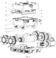
- the use of servo drives and worm gears to adjust corners of the lower portion makes it possible to precisely and independently adjust the motion of each one of the corners, as can be seen in Fig. 3-5 .
- the servo drives and worm gears translate the rotary motion from the servo drives to the linear motion of the corners. This ensures an even and uniform application of the foil.
- An important feature of this solution is the automation of the hot stamping process.
- the hot stamping module works without the need for operator intervention which makes the label production process faster, more efficient and repeatable. This translates into an increase in production efficiency and into waste reduction. This makes the hot stamping module a useful tool for various sectors and production lines.
- the very process of stamping and decorating is a one-step process.
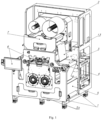
- the embodiment of the device for hot stamping and decorating labels being a module, as seen in Fig. 1 - 6 , can include the following elements: 1 - module supporting frame, 2 - module housing, 3 - decorated material/paper, 4 - rolls guiding the decorated paper/material, 5 - shields, 5a - hinged shields, 6 - operator's panels, 7 - rotatable head, 8 - detecting sensor, 9 - lower NIPs for the decorated material, 10 - lower buffer for the decorated material, 11 - unwinding element for the foil, 12 - winding element for the foil, 13 - foil, 14 - head NIPs in the head, 15 - guiding rolls in the head, 16 - buffer for the foil, 17 - head supporting frame, 18 - head drives in the head, 19 - head housing, 20 - immovable cast-iron block, 21 - aluminium plate with heaters, 22 - slot for the aluminium plate with dies, 23 - upper aluminium slidable plate with dies
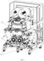
- the module comprises a module supporting frame 1 with a housing 2, with main shafts 31 with cams 35 fixed to the supporting frame and the housing, where the main shafts 31 with cams 35 are responsible for lifting and lowering the lower movable stamping portion 25.
- the system is provided with servo drives, with the main drive 32 being dedicated to driving the main shafts 31.
- the device uses further adjusting servo drives 38 for adjusting the corners of the lower movable portion 25, which makes it possible to quickly and precisely adjust the motion of each of the corners of the lower movable portion 25.
- the device also has worm gears 37, said worm gears 37 for translating the rotary motion from the servo drives, i.e.
- the hot stamping module has an immovable block 20, which is placed in the module frame 1 and located above the movable portion 25. Furthermore, the device also has a rotatable head 7, which is placed on the immovable cast-iron block 20 via a rotatable joint with a bearing. The head 7 rotates counterclockwise (with the module viewed from the top) by 90 degrees. With it being possible to twist the head 7, it is also possible to unwind/wind the foil 13 off/on the head 7 along the decorated material 3 or transversely to the decorated material 3.
- An unwinding element 11 and a winding element 12 for the decorating foil 13 are placed on the rotatable head 7.
- the unwinding elements 11 and winding elements 12 are driven with head servo drives 18 as seen in Fig. 3 , with these devices being used to precisely define the motion of the components of the devices and machines with all parameters being taken into account.
- At least one head buffer 16 for the foil 13 is located on the rotatable head 7.
- the head buffer 16 for the foil 13, as can be seen in Fig. 3 is placed between the shafts and in particular between the head guiding rolls 15 and head NIPs 14. This is a set of rolls, preferably carbon rolls, moving along the foil 13 being unwound.
- two head buffers 16, depending on the number of foils 13 being passed in parallel, and further shafts and guiding rolls 15 in the head 7 can be preferably located on the rotatable head 7, with the head servo drives 18 being coupled with the head NIPs 14, and in particular with two driven rollers and rollers with rubber rolls head NIPs 14, used to synchronise the foil 13 being applied with the paper 3 being decorated, i.e. with the main web.
- the guiding rolls 15 in the head 7 can be, for example, made as ordinary rolls of aluminium.
- the carbon rolls can be, for example, located on the buffer 16 for the foil.
- the rubber rolls are, for example, located on the head NIPs 14 (the so-called drive shafts).
- the head servo drives 18 are connected to the head NIPs 14. It will be at the same time obvious to a person skilled in the art that the dynamics of the foil 13 unwinding system requires the lowest possible moment of inertia, i.e. the lowest mass of the assembly of the rolls and the buffer 16.
- the foil 13 in the rotatable head 7 is guided on subsequent guiding rolls 15 made, for example, of aluminium, and is inserted into the gap between the stamping elements on the head 7 which are adjusted eccentrically.
- the guiding rolls 15, buffer 16, head NIPs 14 are housed in the head supporting frame 17 of the head 7.
- the head servo drives 18 are placed in the housing 19 of the head 7.
- the housing 19 can be made of metal, for example of steel.
- the head 7 has the head supporting frame 17 of aluminium plates positioned vertically with respect to each other and connected with a further metal plate, for example a steel plate, at the base, which all form a kind of a cage for the guiding rolls 15, head NIPs 14, head drives 18, the winding element 12 and the unwinding element 11 for the foil 13, and the buffer 16. It will be obvious to a person skilled in the art that the dimensions, shapes and materials may vary depending on the size of the device in alternative embodiments.
- the head drives 18 are placed on the back of the plate of the supporting frame 17 of the head and are shielded by the housing 19.
- the head 7 is placed on the cast-iron block 20, which is immovable.
- the cast-iron block 20 is located in the frame 1 and is fixed, for example by screws, between the two main plates in the frame 1 of the module, said plates being metal plates, for example steel plates.
- the immovable cast-iron block 20 has a metal plate screwed to its underside, for example an upper aluminium plate 21 with heaters 39 installed.
- This upper aluminium plate 21 with heaters 39 is screwed to the underside of the immovable cast-iron block 20.
- the aluminium plate 21 with heaters 39 is thus located between the upper immovable cast-iron block 20 and the movable block 25 placed underneath, i.e. it is basically located in the gap between the movable block and the immovable bloc, that is in the place where the decorated material 3 and the foil 13 are passed.
- This upper aluminium plate 21, equipped with heaters 39 can be in the shape of, for example, a rectangular cuboid.
- the heaters 39 are controlled automatically with feedback from the temperature sensor 40.
- a slot 22 is located under the upper aluminium plate 21 with heaters 39, said slot for a subsequent layer of an upper slidable plate 23, which is made of metal, for example of aluminium, and which can be slid into and out of slots 22.
- Dies 24 are attached, preferably screwed, to the upper slidable plate 23.
- the dies 24 are preferably and most often brazen dies or are made of bronze, with a label pattern.
- the upper aluminium slidable plate 23 is fixed in such a way that two guides with slots 22, for example metal guides, are screwed to the upper immovable cast-iron block 20, one to each side of it.
- the upper aluminium slidable plate 23, with dies 24 installed, is slid into these guides with slots 22, said dies being fixed, screwed.
- the upper aluminium slidable plate 23 when slid into the slots 22 is blocked with a catch located in the front of the upper immovable cast-iron block 20.
- the foil 13 is passed under the die 24, with the foil being unwound off the head 7 placed on the top of the immovable block 20.
- the lower movable portion 25 is preferably made of cast-iron.
- the lower movable portion 25 of the module is responsible for the entire process of stamping. It can preferably take the shape of the cast-iron block.
- the motion of the lower cast-iron portion 25 makes the decorated material 3 press the die 24.
- this portion, i.e. the lower movable portion 25, moves, the gap between the cast-iron blocks, i.e. between the upper immovable cast-iron block 20 and the lower block being the movable cast-iron portion 25, narrows and the foil 13 is transferred onto the decorated material/label 3.
- the lower movable cast-iron portion 25 has cubic slots 28 and is seated in the housing in the frame 1 of the module via glide cubes 28a, which are preferably made of bronze.
- Bearing blocks 29 are screwed to the underside of the lower movable cast-iron portion 25, with preferably four bearing blocks and essentially in each of the corners, the bearing blocks with barrel bearings 30, as can be seen in Fig.4 , and especially in such a way that the bearing blocks 29 with bearings 30 are screwed to the lower movable block, i.e. the lower movable cast-iron portion 25.
- the bearing blocks 29, whose shape is essentially like that of wheels with bearings 30, directly contact the below cams 35 of the main shafts 31 and rest on them.
- the cams 35 ale located on the rotating main shafts 31.
- the bearing blocks 29 with the barrel bearings 30 rest on the main shafts 31 with cams 35, as can be seen in Fig. 4 .
- the main servo drive 32 is connected to one of the main shafts 31 via a further second driving belt 34.
- the main shafts 31 rotate and lift the lower movable cast-iron portion 25, i.e. the stamping element, on the cams 35.
- the main shafts 31 are placed in the frame 1, with the frame 1 made of steel plates, which, preferably, in the area of the main shafts 31, can for example be steel plates, and in which the main shafts 31 are seated in the bearings in the eccentric mountings 36, as can be seen in Fig. 4 - 5 , and the housing 2 shields the entire module and the servo drives of the module as can be seen in Fig.
- a second lower slot 27 is located in the lower stamping element, i.e. the lower movable cast-iron portion 25, said slot for the lower counter-plate 26, with the counter-plate 26 slid into the lower slot 27, as can be seen in Fig. 4 .
- the counter-plates 26 are for decorating and stamping the decorated material 3 with the foil 13.
- a patrix 26a can be preferably glued to the counter-plate 26, for example using a double-sided adhesive tape or another known connecting agent.
- the patrix 26a is preferably and most often made of resin and is a plate with the reverse of the die 24. With the die 24 and the patrix 26a contacting, during the process of impressing, the decorated material is stamped.
- the position of all the cams 35 on the main shafts 31 is adjusted by the adjusting servo drives 38 for adjusting the pressure exerted in the corners and through worm gears 37.
- the initial pressing and positioning of the lower movable cast-iron portion 25 with respect to the upper portion, i.e. the immovable cast-iron block 20, is implemented automatically by reading the resistances on the adjusting servo drive 38 for adjusting the pressure exerted in the corners.
- the main drive 32 is responsible for the motion of the lower movable cast-iron portion 25 to the extreme bottom and the extreme top.
- the adjusting servo drives 38 for adjusting the pressure in the corners adjust the pressure (i.e. the distance/gap between the lower movable cast-iron portion 25 and the immovable cast-iron block 20) in the extreme top position of the lower movable cast-iron portion 25.
- the resistances are read from the drives in the corners, i.e. from the adjusting drives 38 for adjusting the pressure exerted in the corners.
- a lower buffer 10 for the decorated material 3 is located under the main shafts 31, said buffer being controlled at the inlet and outlet of the module with the system with two driven lower rollers and rollers with rubber rolls lower NIPs 9 of the decorated material 3, wherein the lower servo drives 41, which drive the rollers, are placed in the housing 2 of the module, as can be seen in Fig. 6 , which will be known to a person skilled in the art.
- This makes it possible to synchronise the web of, for example, paper, i.e. the decorated material 3 - with the detecting sensor 8 coupled, said sensor checking the position of the decorated material 3, and in particular the main decorated material 3 - with the labels by reading a marker on the decorated material 3.
- the decorated material 3 is guided on further rolls made of, for example, aluminium.
- the shape of the cams 35 is selected such that in the upper most part of the shape it is flattened with respect to the circle circumscribed on that cam.
- the time of bonding i.e. the time of the foil 13 contacting the decorated material 3 is increased.
- the entire front and lower portion of the module, i.e. the main shafts 31 with cams 35 and the lower buffer 10 of the decorated material 3 are shielded with screwed panels, i.e. shields 5.
- the access to the movable or inner portions is secured with hinged shields 5a.
- the openable shields, the hinged shields 5a, are all equipped with security sensors, which is obvious to a person skilled in the art.
- the module is controlled entirely with the use of controllers by means of an operator's panel 6, which can preferably have buttons and/or a potentiometer, as can be seen in Fig.1 . All information is visible in the additional operator's panel with a display and/or with a touching option, in alternative embodiments.
- the present invention can be used in the hot stamping and decorating of labels.
- the modules can be used to improve the quality and aesthetics of labels by applying metallised foil to their surface. They are used, inter alia , in the printing industry to produce labels for products such as packagings, food products, cosmetics and chemicals etc.
Landscapes
- Engineering & Computer Science (AREA)
- Mechanical Engineering (AREA)
- Physics & Mathematics (AREA)
- General Physics & Mathematics (AREA)
- Theoretical Computer Science (AREA)
- Labeling Devices (AREA)
Applications Claiming Priority (1)
| Application Number | Priority Date | Filing Date | Title |
|---|---|---|---|
| PL445998A PL445998A1 (pl) | 2023-09-04 | 2023-09-04 | Urządzenie i sposób do obrabiania etykiet |
Publications (1)
| Publication Number | Publication Date |
|---|---|
| EP4516510A1 true EP4516510A1 (fr) | 2025-03-05 |
Family
ID=93257696
Family Applications (1)
| Application Number | Title | Priority Date | Filing Date |
|---|---|---|---|
| EP24197999.6A Pending EP4516510A1 (fr) | 2023-09-04 | 2024-09-02 | Dispositif et procédé de traitement d'étiquettes |
Country Status (2)
| Country | Link |
|---|---|
| EP (1) | EP4516510A1 (fr) |
| PL (1) | PL445998A1 (fr) |
Citations (6)
| Publication number | Priority date | Publication date | Assignee | Title |
|---|---|---|---|---|
| CN102615960A (zh) * | 2012-03-28 | 2012-08-01 | 天津长荣印刷设备股份有限公司 | 一种调压装置及其工作方法 |
| CN103286815A (zh) * | 2013-05-10 | 2013-09-11 | 天津长荣印刷设备股份有限公司 | 一种模切平台伺服退压系统及其工作方法 |
| CN103373051B (zh) * | 2012-04-28 | 2015-11-18 | 上海旭恒精工机械制造有限公司 | 保压时间可调的模切/烫印平台驱动机构 |
| EP3150367A1 (fr) | 2015-09-28 | 2017-04-05 | Cartes S.r.l. | Dispositif pour traiter un matériau flexible |
| EP3150368A1 (fr) | 2015-09-28 | 2017-04-05 | Cartes S.r.l. | Dispositif et procede pour fabriquer des portions discretes |
| CN106863998B (zh) * | 2017-03-14 | 2019-01-11 | 深圳市博泰印刷设备有限公司 | 一种3d平烫金设备 |
Family Cites Families (4)
| Publication number | Priority date | Publication date | Assignee | Title |
|---|---|---|---|---|
| DE3210551C2 (de) * | 1982-03-23 | 1984-11-08 | Fa. Leonhard Kurz, 8510 Fürth | Verfahren und Vorrichtung zum Anbringen eines Prägefolien-Abdruckes auf einer flexiblen Materialbahn |
| US6334248B1 (en) * | 1996-09-20 | 2002-01-01 | Total Register, Inc. | Apparatus and method for the continuous high speed rotary application of stamping foil |
| PL422765A1 (pl) * | 2017-09-06 | 2019-03-11 | Grafotronic Spółka Z Ograniczoną Odpowiedzialnością | Moduł maszyny z funkcją sztancowania |
| CN108582990B (zh) * | 2018-06-29 | 2023-08-25 | 新乡市鼎鑫机械有限公司 | 多功能压纹转移复合生产设备及其生产方法 |
-
2023
- 2023-09-04 PL PL445998A patent/PL445998A1/pl unknown
-
2024
- 2024-09-02 EP EP24197999.6A patent/EP4516510A1/fr active Pending
Patent Citations (6)
| Publication number | Priority date | Publication date | Assignee | Title |
|---|---|---|---|---|
| CN102615960A (zh) * | 2012-03-28 | 2012-08-01 | 天津长荣印刷设备股份有限公司 | 一种调压装置及其工作方法 |
| CN103373051B (zh) * | 2012-04-28 | 2015-11-18 | 上海旭恒精工机械制造有限公司 | 保压时间可调的模切/烫印平台驱动机构 |
| CN103286815A (zh) * | 2013-05-10 | 2013-09-11 | 天津长荣印刷设备股份有限公司 | 一种模切平台伺服退压系统及其工作方法 |
| EP3150367A1 (fr) | 2015-09-28 | 2017-04-05 | Cartes S.r.l. | Dispositif pour traiter un matériau flexible |
| EP3150368A1 (fr) | 2015-09-28 | 2017-04-05 | Cartes S.r.l. | Dispositif et procede pour fabriquer des portions discretes |
| CN106863998B (zh) * | 2017-03-14 | 2019-01-11 | 深圳市博泰印刷设备有限公司 | 一种3d平烫金设备 |
Also Published As
| Publication number | Publication date |
|---|---|
| PL445998A1 (pl) | 2025-03-10 |
Similar Documents
| Publication | Publication Date | Title |
|---|---|---|
| EP0868998B1 (fr) | Machine de traitement de bandes à grande vitesse | |
| US9199388B2 (en) | System for finishing printed labels using multiple X-Y cutters | |
| US4805501A (en) | System for processing a web | |
| EP1447186B1 (fr) | Procédé de contrôle pour une machine à refendre et à rainurer | |
| JP5053041B2 (ja) | ブランクから折畳み箱を製造するための製函機 | |
| EP3450156B1 (fr) | Dispositif de pliage de feuille et machine de fabrication de boîte | |
| US5115737A (en) | Hot rotary stamper apparatus and methods for metal leaf stamping | |
| US20130042771A1 (en) | Apparatus and method for treating products | |
| CA2092908A1 (fr) | Mecanisme de coupe a organe rotatif | |
| US4882004A (en) | Compact tabletop machine for making labels and other laminations | |
| EP4516510A1 (fr) | Dispositif et procédé de traitement d'étiquettes | |
| CN114772366A (zh) | 包括带施加头的设备 | |
| CN113631360A (zh) | 尺寸可变的盖制造方法以及尺寸可变的盖制造装置 | |
| US6796553B2 (en) | Arrangement for applying and pressing on covers | |
| US10173364B2 (en) | Control method of embossing apparatus | |
| CN219749226U (zh) | 一种丝网印刷冷烫机 | |
| CN216609326U (zh) | 一种大尺寸标签印件模切装置 | |
| CN210680068U (zh) | 预涂胶离线定位烫金机 | |
| EP2613941B1 (fr) | Procédé et appareil pour produire des matrices mâles pour le gaufrage de caractères braille et des matrices mâles correspondants | |
| US20160243815A1 (en) | Embossing apparatus | |
| CN223071984U (zh) | 一种瓦楞纸板覆膜机弹跳辊断纸设备 | |
| US4827292A (en) | Skewed material advancing system | |
| RU2196684C1 (ru) | Способ горячего тиснения фольгой | |
| WO1996009168A1 (fr) | Dispositif d'etiquetage continu d'une bande sans fin | |
| CN112969591A (zh) | 全息箔供应装置以及热箔压印机 |
Legal Events
| Date | Code | Title | Description |
|---|---|---|---|
| PUAI | Public reference made under article 153(3) epc to a published international application that has entered the european phase |
Free format text: ORIGINAL CODE: 0009012 |
|
| STAA | Information on the status of an ep patent application or granted ep patent |
Free format text: STATUS: REQUEST FOR EXAMINATION WAS MADE |
|
| 17P | Request for examination filed |
Effective date: 20240902 |
|
| AK | Designated contracting states |
Kind code of ref document: A1 Designated state(s): AL AT BE BG CH CY CZ DE DK EE ES FI FR GB GR HR HU IE IS IT LI LT LU LV MC ME MK MT NL NO PL PT RO RS SE SI SK SM TR |