EP4516567A1 - Dispositif d'entraînement de véhicule - Google Patents
Dispositif d'entraînement de véhicule Download PDFInfo
- Publication number
- EP4516567A1 EP4516567A1 EP23871996.7A EP23871996A EP4516567A1 EP 4516567 A1 EP4516567 A1 EP 4516567A1 EP 23871996 A EP23871996 A EP 23871996A EP 4516567 A1 EP4516567 A1 EP 4516567A1
- Authority
- EP
- European Patent Office
- Prior art keywords
- rotary member
- lock
- rotational position
- drive device
- torque
- Prior art date
- Legal status (The legal status is an assumption and is not a legal conclusion. Google has not performed a legal analysis and makes no representation as to the accuracy of the status listed.)
- Pending
Links
Images


Classifications
-
- B—PERFORMING OPERATIONS; TRANSPORTING
- B60—VEHICLES IN GENERAL
- B60T—VEHICLE BRAKE CONTROL SYSTEMS OR PARTS THEREOF; BRAKE CONTROL SYSTEMS OR PARTS THEREOF, IN GENERAL; ARRANGEMENT OF BRAKING ELEMENTS ON VEHICLES IN GENERAL; PORTABLE DEVICES FOR PREVENTING UNWANTED MOVEMENT OF VEHICLES; VEHICLE MODIFICATIONS TO FACILITATE COOLING OF BRAKES
- B60T1/00—Arrangements of braking elements, i.e. of those parts where braking effect occurs specially for vehicles
- B60T1/005—Arrangements of braking elements, i.e. of those parts where braking effect occurs specially for vehicles by locking of wheel or transmission rotation
-
- B—PERFORMING OPERATIONS; TRANSPORTING
- B60—VEHICLES IN GENERAL
- B60L—PROPULSION OF ELECTRICALLY-PROPELLED VEHICLES; SUPPLYING ELECTRIC POWER FOR AUXILIARY EQUIPMENT OF ELECTRICALLY-PROPELLED VEHICLES; ELECTRODYNAMIC BRAKE SYSTEMS FOR VEHICLES IN GENERAL; MAGNETIC SUSPENSION OR LEVITATION FOR VEHICLES; MONITORING OPERATING VARIABLES OF ELECTRICALLY-PROPELLED VEHICLES; ELECTRIC SAFETY DEVICES FOR ELECTRICALLY-PROPELLED VEHICLES
- B60L15/00—Methods, circuits, or devices for controlling the traction-motor speed of electrically-propelled vehicles
- B60L15/20—Methods, circuits, or devices for controlling the traction-motor speed of electrically-propelled vehicles for control of the vehicle or its driving motor to achieve a desired performance, e.g. speed, torque, programmed variation of speed
-
- B—PERFORMING OPERATIONS; TRANSPORTING
- B60—VEHICLES IN GENERAL
- B60L—PROPULSION OF ELECTRICALLY-PROPELLED VEHICLES; SUPPLYING ELECTRIC POWER FOR AUXILIARY EQUIPMENT OF ELECTRICALLY-PROPELLED VEHICLES; ELECTRODYNAMIC BRAKE SYSTEMS FOR VEHICLES IN GENERAL; MAGNETIC SUSPENSION OR LEVITATION FOR VEHICLES; MONITORING OPERATING VARIABLES OF ELECTRICALLY-PROPELLED VEHICLES; ELECTRIC SAFETY DEVICES FOR ELECTRICALLY-PROPELLED VEHICLES
- B60L15/00—Methods, circuits, or devices for controlling the traction-motor speed of electrically-propelled vehicles
- B60L15/20—Methods, circuits, or devices for controlling the traction-motor speed of electrically-propelled vehicles for control of the vehicle or its driving motor to achieve a desired performance, e.g. speed, torque, programmed variation of speed
- B60L15/2072—Methods, circuits, or devices for controlling the traction-motor speed of electrically-propelled vehicles for control of the vehicle or its driving motor to achieve a desired performance, e.g. speed, torque, programmed variation of speed for drive off
- B60L15/2081—Methods, circuits, or devices for controlling the traction-motor speed of electrically-propelled vehicles for control of the vehicle or its driving motor to achieve a desired performance, e.g. speed, torque, programmed variation of speed for drive off for drive off on a slope
-
- F—MECHANICAL ENGINEERING; LIGHTING; HEATING; WEAPONS; BLASTING
- F16—ENGINEERING ELEMENTS AND UNITS; GENERAL MEASURES FOR PRODUCING AND MAINTAINING EFFECTIVE FUNCTIONING OF MACHINES OR INSTALLATIONS; THERMAL INSULATION IN GENERAL
- F16D—COUPLINGS FOR TRANSMITTING ROTATION; CLUTCHES; BRAKES
- F16D63/00—Brakes not otherwise provided for; Brakes combining more than one of the types of groups F16D49/00 - F16D61/00
- F16D63/006—Positive locking brakes
-
- F—MECHANICAL ENGINEERING; LIGHTING; HEATING; WEAPONS; BLASTING
- F16—ENGINEERING ELEMENTS AND UNITS; GENERAL MEASURES FOR PRODUCING AND MAINTAINING EFFECTIVE FUNCTIONING OF MACHINES OR INSTALLATIONS; THERMAL INSULATION IN GENERAL
- F16H—GEARING
- F16H63/00—Control outputs from the control unit to change-speed- or reversing-gearings for conveying rotary motion or to other devices than the final output mechanism
- F16H63/02—Final output mechanisms therefor; Actuating means for the final output mechanisms
- F16H63/30—Constructional features of the final output mechanisms
- F16H63/34—Locking or disabling mechanisms
- F16H63/3416—Parking lock mechanisms or brakes in the transmission
- F16H63/3441—Parking locks engaging axially
-
- B—PERFORMING OPERATIONS; TRANSPORTING
- B60—VEHICLES IN GENERAL
- B60L—PROPULSION OF ELECTRICALLY-PROPELLED VEHICLES; SUPPLYING ELECTRIC POWER FOR AUXILIARY EQUIPMENT OF ELECTRICALLY-PROPELLED VEHICLES; ELECTRODYNAMIC BRAKE SYSTEMS FOR VEHICLES IN GENERAL; MAGNETIC SUSPENSION OR LEVITATION FOR VEHICLES; MONITORING OPERATING VARIABLES OF ELECTRICALLY-PROPELLED VEHICLES; ELECTRIC SAFETY DEVICES FOR ELECTRICALLY-PROPELLED VEHICLES
- B60L2240/00—Control parameters of input or output; Target parameters
- B60L2240/40—Drive Train control parameters
- B60L2240/46—Drive Train control parameters related to wheels
-
- B—PERFORMING OPERATIONS; TRANSPORTING
- B60—VEHICLES IN GENERAL
- B60L—PROPULSION OF ELECTRICALLY-PROPELLED VEHICLES; SUPPLYING ELECTRIC POWER FOR AUXILIARY EQUIPMENT OF ELECTRICALLY-PROPELLED VEHICLES; ELECTRODYNAMIC BRAKE SYSTEMS FOR VEHICLES IN GENERAL; MAGNETIC SUSPENSION OR LEVITATION FOR VEHICLES; MONITORING OPERATING VARIABLES OF ELECTRICALLY-PROPELLED VEHICLES; ELECTRIC SAFETY DEVICES FOR ELECTRICALLY-PROPELLED VEHICLES
- B60L2260/00—Operating Modes
- B60L2260/20—Drive modes; Transition between modes
- B60L2260/22—Standstill, e.g. zero speed
-
- B—PERFORMING OPERATIONS; TRANSPORTING
- B60—VEHICLES IN GENERAL
- B60Y—INDEXING SCHEME RELATING TO ASPECTS CROSS-CUTTING VEHICLE TECHNOLOGY
- B60Y2200/00—Type of vehicle
- B60Y2200/90—Vehicles comprising electric prime movers
- B60Y2200/91—Electric vehicles
-
- F—MECHANICAL ENGINEERING; LIGHTING; HEATING; WEAPONS; BLASTING
- F16—ENGINEERING ELEMENTS AND UNITS; GENERAL MEASURES FOR PRODUCING AND MAINTAINING EFFECTIVE FUNCTIONING OF MACHINES OR INSTALLATIONS; THERMAL INSULATION IN GENERAL
- F16H—GEARING
- F16H63/00—Control outputs from the control unit to change-speed- or reversing-gearings for conveying rotary motion or to other devices than the final output mechanism
- F16H63/02—Final output mechanisms therefor; Actuating means for the final output mechanisms
- F16H63/30—Constructional features of the final output mechanisms
- F16H63/34—Locking or disabling mechanisms
- F16H63/3416—Parking lock mechanisms or brakes in the transmission
- F16H63/3425—Parking lock mechanisms or brakes in the transmission characterised by pawls or wheels
-
- F—MECHANICAL ENGINEERING; LIGHTING; HEATING; WEAPONS; BLASTING
- F16—ENGINEERING ELEMENTS AND UNITS; GENERAL MEASURES FOR PRODUCING AND MAINTAINING EFFECTIVE FUNCTIONING OF MACHINES OR INSTALLATIONS; THERMAL INSULATION IN GENERAL
- F16H—GEARING
- F16H63/00—Control outputs from the control unit to change-speed- or reversing-gearings for conveying rotary motion or to other devices than the final output mechanism
- F16H63/02—Final output mechanisms therefor; Actuating means for the final output mechanisms
- F16H63/30—Constructional features of the final output mechanisms
- F16H63/34—Locking or disabling mechanisms
- F16H63/3416—Parking lock mechanisms or brakes in the transmission
- F16H63/3458—Parking lock mechanisms or brakes in the transmission with electric actuating means, e.g. shift by wire
- F16H63/3475—Parking lock mechanisms or brakes in the transmission with electric actuating means, e.g. shift by wire using solenoids
-
- F—MECHANICAL ENGINEERING; LIGHTING; HEATING; WEAPONS; BLASTING
- F16—ENGINEERING ELEMENTS AND UNITS; GENERAL MEASURES FOR PRODUCING AND MAINTAINING EFFECTIVE FUNCTIONING OF MACHINES OR INSTALLATIONS; THERMAL INSULATION IN GENERAL
- F16H—GEARING
- F16H63/00—Control outputs from the control unit to change-speed- or reversing-gearings for conveying rotary motion or to other devices than the final output mechanism
- F16H63/40—Control outputs from the control unit to change-speed- or reversing-gearings for conveying rotary motion or to other devices than the final output mechanism comprising signals other than signals for actuating the final output mechanisms
- F16H63/48—Signals to a parking brake or parking lock; Control of parking locks or brakes being part of the transmission
- F16H63/483—Circuits for controlling engagement of parking locks or brakes
-
- F—MECHANICAL ENGINEERING; LIGHTING; HEATING; WEAPONS; BLASTING
- F16—ENGINEERING ELEMENTS AND UNITS; GENERAL MEASURES FOR PRODUCING AND MAINTAINING EFFECTIVE FUNCTIONING OF MACHINES OR INSTALLATIONS; THERMAL INSULATION IN GENERAL
- F16H—GEARING
- F16H63/00—Control outputs from the control unit to change-speed- or reversing-gearings for conveying rotary motion or to other devices than the final output mechanism
- F16H63/40—Control outputs from the control unit to change-speed- or reversing-gearings for conveying rotary motion or to other devices than the final output mechanism comprising signals other than signals for actuating the final output mechanisms
- F16H63/50—Signals to an engine or motor
-
- Y—GENERAL TAGGING OF NEW TECHNOLOGICAL DEVELOPMENTS; GENERAL TAGGING OF CROSS-SECTIONAL TECHNOLOGIES SPANNING OVER SEVERAL SECTIONS OF THE IPC; TECHNICAL SUBJECTS COVERED BY FORMER USPC CROSS-REFERENCE ART COLLECTIONS [XRACs] AND DIGESTS
- Y02—TECHNOLOGIES OR APPLICATIONS FOR MITIGATION OR ADAPTATION AGAINST CLIMATE CHANGE
- Y02T—CLIMATE CHANGE MITIGATION TECHNOLOGIES RELATED TO TRANSPORTATION
- Y02T10/00—Road transport of goods or passengers
- Y02T10/60—Other road transportation technologies with climate change mitigation effect
- Y02T10/62—Hybrid vehicles
-
- Y—GENERAL TAGGING OF NEW TECHNOLOGICAL DEVELOPMENTS; GENERAL TAGGING OF CROSS-SECTIONAL TECHNOLOGIES SPANNING OVER SEVERAL SECTIONS OF THE IPC; TECHNICAL SUBJECTS COVERED BY FORMER USPC CROSS-REFERENCE ART COLLECTIONS [XRACs] AND DIGESTS
- Y02—TECHNOLOGIES OR APPLICATIONS FOR MITIGATION OR ADAPTATION AGAINST CLIMATE CHANGE
- Y02T—CLIMATE CHANGE MITIGATION TECHNOLOGIES RELATED TO TRANSPORTATION
- Y02T10/00—Road transport of goods or passengers
- Y02T10/60—Other road transportation technologies with climate change mitigation effect
- Y02T10/72—Electric energy management in electromobility
Definitions
- the present invention relates to a vehicle drive device including a rotating electrical machine that functions as a driving force source of wheels, and a parking lock mechanism that selectively restricts rotation of a rotary member that rotates in conjunction with the wheels.
- Patent Literature 1 An example of such a vehicle drive device is disclosed in Patent Literature 1 below.
- reference signs in Patent Literature 1 are cited in parentheses.
- a parking lock mechanism (78) includes a parking lock gear (76) disposed on a power transmission path connecting a rotating electrical machine (12) and wheels (68, 74), a parking pawl (80) that restricts rotation of the parking lock gear, and a drive device (82) that drives the parking pawl (refer to FIG. 1 in Patent Literature 1).
- Patent Literature 1 JP 2003-264908 A
- Patent Literature 1 discloses that, in the above case, torque of the rotating electrical machine (12) is controlled so as to reduce the load acting on the engagement portion between the parking lock gear (76) and the parking pawl (80).
- Patent Literature 1 does not disclose a point of determining a direction of the load acting on the engagement portion between the parking lock gear (76) and the parking pawl (80). Therefore, in the above-described vehicle drive device (10), it has been difficult to appropriately control the torque of the rotating electrical machine (12) so as to reduce the load acting on the engagement portion between the parking lock gear (76) and the parking pawl (80).
- a characteristic configuration of a vehicle drive device is that
- the wheel torque direction is determined on the basis of the direction in which the detected rotational position is deviated from the theoretical lock position due to the backlash.
- torque in a direction to weaken engagement force between the lock member and the first rotary member can be appropriately output to the rotating electrical machine. Therefore, it is possible to appropriately control torque of the rotating electrical machine in a case of unlocking the parking lock mechanism. In this way, even in a case where driving force of the drive device cannot move the lock member from the lock position to the unlock position side, engagement force between the lock member and the first rotary member can be weakened by using the torque of the rotating electrical machine, and thus the driving force of the drive device can unlock the parking lock mechanism.
- the characteristic configuration it is possible to eliminate need for various sensors, such as an inclination angle sensor, for determining the wheel torque direction. Therefore, it is easy to simplify and reduce costs for a configuration of the vehicle drive device.
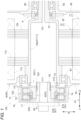
- the vehicle drive device 100 includes a rotating electrical machine 1, a rotational position sensor 8, and a parking lock mechanism 10.
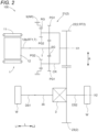
- the rotating electrical machine 1 functions as a driving force source for wheels W (refer to FIG. 2 ) included in a vehicle.
- the rotating electrical machine 1 has a function as a motor (electric motor) that receives electric power supply to generate power, and a function as a generator (generator) that receives supply of power to generates electric power.
- the rotating electrical machine 1 is electrically coupled to a power storage device (not shown) such as a battery and a capacitor. Then, the rotating electrical machine 1 is powered by electric power stored in the power storage device to generate driving force. Furthermore, the rotating electrical machine 1 generates electric power with the driving force transmitted from the wheels W side and charges the power storage device.
- the rotating electrical machine 1 includes a stator 11 and a rotor 12.
- the stator 11 includes a stator core 11a having a cylindrical shape.
- the stator core 11a is fixed to a non-rotary member NR.
- the rotor 12 includes a rotor core 12a having a cylindrical shape.
- the rotor core 12a is rotatably supported with respect to the stator core 11a.
- the rotor 12 further includes a rotor shaft 12b coupled to the rotor core 12a so as to rotate integrally with the rotor core 12a.
- a direction along a rotation axis of the rotor 12 is referred to as an "axial direction L".
- one side in the axial direction L is referred to as an "axial direction first side L1”
- another side in the axial direction L is referred to as an "axial direction second side L2”.
- a direction orthogonal to the axial direction L is referred to as a "radial direction R”.
- the radial direction R is defined with reference to each rotation axis of a rotary member such as the rotor 12. Note that, when it is not necessary to distinguish which rotation axis is used as the reference or when it is clear which rotation axis is used as the reference, the direction may be simply referred to as the "radial direction R".
- the rotor shaft 12b is formed in a tubular shape having an axis along the axial direction L. Then, the rotor shaft 12b is disposed so as to protrude from the rotor core 12a toward each of the axial direction first side L1 and the axial direction second side L2.
- the rotating electrical machine 1 is an inner rotor type rotating electrical machine. Therefore, the rotor core 12a is disposed inside of the stator core 11a in the radial direction R. Furthermore, the rotor shaft 12b is disposed inside of the rotor core 12a in the radial direction R.
- the rotating electrical machine 1 is a revolving-field type rotating electrical machine. Therefore, a stator coil is wound around the stator core 11a.
- the stator coil is wound around the stator core 11a such that coil end portions 11b protruding on the axial direction first side L1 and the axial direction second side L2 from the stator core 11a are formed.
- the rotor core 12a is provided with a permanent magnet.
- the rotational position sensor 8 is a sensor for detecting a rotational position of a target rotary member T that is either a first rotary member RT1 or a second rotary member RT2.
- the target rotary member T is the first rotary member RT1.
- the first rotary member RT1 is the rotor shaft 12b.
- Each of the first rotary member RT1 and the second rotary member RT2 is a rotary member that rotates in conjunction with the wheels W (refer to FIG. 2 ).
- the second rotary member RT2 is disposed on the wheels W side with respect to the first rotary member RT1 on a power transmission path connecting the rotating electrical machine 1 and the wheels W.
- the parking lock mechanism 10 selectively restricts rotation of the first rotary member RT1. Note that a detailed configuration of the parking lock mechanism 10 will be described later.
- the vehicle drive device 100 further includes a power transmission mechanism 2, a differential gear mechanism 3, and a case 9.
- the power transmission mechanism 2 transmits rotation of the rotor 12 to the differential gear mechanism 3.
- the power transmission mechanism 2 includes a planetary gear mechanism 21, a first gear 22, and a second gear 23.
- the planetary gear mechanism 21 and the first gear 22 are disposed on a first axis X1 that is the rotation axis of the rotor 12.
- the second gear 23 is disposed on a second axis X2 different from the first axis X1.
- the planetary gear mechanism 21 is configured so as to decelerate the rotation of the rotor 12 and transmit the rotation to the first gear 22.
- the planetary gear mechanism 21 includes a sun gear SG, a carrier CR, and ring gears RG.
- the sun gear SG is coupled to the rotor 12 so as to rotate integrally with the rotor 12. That is, the sun gear SG is an input element of the planetary gear mechanism 21.
- the sun gear SG is coupled to the rotor shaft 12b via an input shaft I so as to rotate integrally with the rotor shaft 12b.
- the input shaft I is formed so as to extend along the axial direction L. In the present embodiment, the input shaft I is formed so as to extend from the sun gear SG to the axial direction first side L1.
- the carrier CR rotatably supports first pinion gears PG1 and second pinion gears PG2 that rotate integrally with each other.
- Each of the first pinion gears PG1 and the second pinion gears PG2 rotates (rotates) about its own axis and rotates (revolves) about the sun gear SG, together with the carrier CR.
- a plurality of the first pinion gears PG1 and a plurality of the second pinion gears PG2 are provided at intervals from one another along a revolution trajectory of own.
- the first pinion gears PG1 mesh with the sun gear SG.
- the second pinion gears PG2 mesh with the ring gears RG.
- the second pinion gears PG2 are formed to have a diameter smaller than a diameter of the first pinion gears PG1.
- the second pinion gears PG2 are disposed on the axial direction first side L1 with respect to the first pinion gears PG1.
- the carrier CR is coupled to the first gear 22 so as to rotate integrally with the first gear 22. That is, the carrier CR is an output element of the planetary gear mechanism 21.
- the first gear 22 is disposed on the axial direction second side L2 with respect to the planetary gear mechanism 21. Note that, in the present embodiment, the first gear 22 is the second rotary member RT2.
- the ring gears RG are fixed to the non-rotary member NR.
- the ring gears RG are fixed to the case 9 as the non-rotary member NR.
- the first gear 22 and the second gear 23 mesh with each other.
- the second gear 23 is formed to have a diameter larger than a diameter of the first gear 22. Therefore, in the present embodiment, rotation of the carrier CR of the planetary gear mechanism 21 is decelerated between the first gear 22 and the second gear 23 and transmitted to the differential gear mechanism 3.
- the differential gear mechanism 3 distributes the rotation transmitted from the power transmission mechanism 2 to a pair of the wheels W.
- the differential gear mechanism 3 is disposed on the second axis X2.
- the differential gear mechanism 3 is a bevel-gear type differential gear mechanism.
- the differential gear mechanism 3 includes a pair of pinion gears, a first side gear and a second side gear that mesh with the pair of pinion gears, and a differential case housing these gears.
- the differential case is coupled to the second gear 23 so as to rotate integrally with the second gear 23. Furthermore, the differential case is coupled to a pinion shaft, which rotatably supports the pair of pinion gears, so as to rotate integrally with the pinion shaft.
- the first side gear is coupled, via a transmission shaft 35 extending along the axial direction L, to a first drive shaft DS1, which is drivingly coupled to a wheel W on the axial direction first side L1, so as to rotate integrally with a first drive shaft DS1.
- the second side gear is coupled to a second drive shaft DS2, which is drivingly coupled to a wheel W on the axial direction second side L2, so as to rotate integrally with a second drive shaft DS2.
- the case 9 houses the rotating electrical machine 1, the power transmission mechanism 2, the differential gear mechanism 3, and the parking lock mechanism 10. As shown in FIG. 1 , in the present embodiment, the case 9 includes a first tubular portion 91, a second tubular portion 92, a third tubular portion 93, a first side-wall portion 94, a second side-wall portion 95, and a third side-wall portion 96.
- first tubular portion 91 and the second tubular portion 92 is formed in a tubular shape concentric with the rotor 12.
- first tubular portion 91 is disposed outside of a portion of the rotor shaft 12b in the radial direction R, the portion protruding from the rotor core 12a toward the axial direction first side L1.
- second tubular portion 92 is disposed inside of a portion of the rotor shaft 12b in the radial direction R, the portion protruding from the rotor core 12a toward the axial direction first side L1.
- the rotor shaft 12b is rotatably supported with respect to the case 9 via a first rotor bearing B1 disposed between the rotor shaft 12b and the first tubular portion 91 in the radial direction R.
- the first side-wall portion 94 is formed so as to extend outward in the radial direction R from the first tubular portion 91.
- the first side-wall portion 94 is disposed so as to cover the axial direction first side L1 of the rotating electrical machine 1.
- the second side-wall portion 95 is formed so as to extend inward in the radial direction R from the first tubular portion 91.
- the second side-wall portion 95 is disposed on the axial direction first side L1 with respect to the first side-wall portion 94.
- the second side-wall portion 95 is coupled to an end of the first tubular portion 91 on the axial direction first side L1 so as to cover the first tubular portion 91 from the axial direction first side L1.
- the second tubular portion 92 is formed so as to extend from the second side-wall portion 95 toward the axial direction second side L2.
- the third tubular portion 93 is formed in a tubular shape concentric with the rotor 12.
- a portion of the rotor shaft 12b, the portion protruding from the rotor core 12a toward the axial direction second side L2 has a small-diameter portion 12c formed to have a diameter smaller than a diameter of a portion of the rotor shaft 12b, the portion being coupled to the rotor core 12a.
- the third tubular portion 93 is disposed outside the small-diameter portion 12c of the rotor shaft 12b in the radial direction R.
- the rotor shaft 12b is rotatably supported with respect to the case 9 via a second rotor bearing B2 disposed between the small-diameter portion 12c and the third tubular portion 93 in the radial direction R.
- the third side-wall portion 96 is formed so as to extend outward in the radial direction R from the third tubular portion 93.
- the third side-wall portion 96 is disposed so as to cover the axial direction second side L2 of the rotating electrical machine 1.
- the third tubular portion 93 is formed so as to extend to the axial direction second side L2 from an inner end of the third side-wall portion 96 in the radial direction R.
- the rotational position sensor 8 includes a sensor stator 81 fixed to the non-rotary member NR and a sensor rotor 82 rotatably supported with respect to the sensor stator 81.
- the rotational position sensor 8 is configured as a resolver. Therefore, the rotational position sensor 8 detects the rotational position of the target rotary member T by detecting a phase of alternating-current voltage corresponding to a relative angle of the sensor rotor 82 with respect to the sensor stator 81 when alternating current is applied to a coil provided in the sensor stator 81.
- the rotational position sensor 8 is not limited to the resolver, and can include various kinds of sensors, such as a Hall element sensor, an encoder, and a magnetic rotation sensor, for example.
- the sensor stator 81 is fixed to the third side-wall portion 96 of the case 9 as the non-rotary member NR. Then, the sensor stator 81 is disposed so as to protrude inward in the radial direction R from the third tubular portion 93 of the case 9. Furthermore, the sensor rotor 82 is coupled to the small-diameter portion 12c so as to rotate integrally with the rotor shaft 12b as the target rotary member T. Then, the sensor rotor 82 is disposed so as to face the sensor stator 81 from inside in the radial direction R.
- the parking lock mechanism 10 includes a lock member 4 and a drive device 5.
- the lock member 4 is configured to be movable to a lock position P1 at which the lock member 4 is engaged with the first rotary member RT1 to restrict the rotation of the first rotary member RT1, and to an unlock position P2 at which the lock member 4 is separated from the first rotary member RT1 to allow the rotation of the first rotary member RT1.
- the lock member 4 is supported so as to be relatively non-rotatable with respect to the non-rotary member NR.
- the lock member 4 includes a tubular portion 41 formed in a tubular shape concentric with the rotor 12. The tubular portion 41 is disposed outside the second tubular portion 92 of the case 9 in the radial direction R.
- the lock member 4 includes a plurality of first engaging portions 411.
- the case 9 includes a plurality of first engaged portions 921 with which the plurality of first engaging portions 411 are engaged.
- a direction along a direction in which the first rotary member RT1 rotates is referred to as a "circumferential direction C”.
- one side in the circumferential direction C is referred to as a “circumferential direction first side C1”
- another side in the circumferential direction C is referred to as a "circumferential direction second side C2".
- each of the plurality of first engaging portions 411 and the plurality of first engaged portions 921 is disposed in the circumferential direction C.
- each of the plurality of first engaging portions 411 is a tooth portion formed on an inner peripheral surface of the tubular portion 41 of the lock member 4.
- each of the plurality of first engaged portions 921 is a tooth portion formed on an outer peripheral surface of the second tubular portion 92 of the case 9. Then, the plurality of first engaging portions 411 are movable in the axial direction L and are meshed with the plurality of first engaged portions 921 so as to be relatively non-rotatable.
- the plurality of first engaging portions 411 and the plurality of first engaged portions 921 are arranged at equal intervals in the circumferential direction C, and are continuously formed along the axial direction L.
- the lock member 4 includes second engaging portions 412.
- the first rotary member RT1 includes a plurality of second engaged portions Ta with which the second engaging portions 412 are engaged.
- each of the second engaging portions 412 corresponds to an "engaging portion”
- each of the second engaged portions Ta corresponds to an "engaged portion”.
- the plurality of second engaged portions Ta are disposed in the circumferential direction C.
- each of the plurality of second engaged portions Ta is a tooth portion formed on an inner peripheral surface of the first rotary member RT1 (here, the rotor shaft 12b).
- the plurality of second engaged portions Ta are arranged at equal intervals in the circumferential direction C.
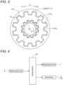
- a plurality of second engaging portions 412 are disposed in the circumferential direction C. Then, each of the plurality of second engaging portions 412 is a tooth portion formed on an outer peripheral surface of the tubular portion 41 of the lock member 4. In the example shown in FIG. 3 , the plurality of second engaging portions 412 are arranged at equal intervals in the circumferential direction C.
- the plurality of second engaging portions 412 are engaged with the plurality of second engaged portions Ta from the axial direction first side L1 so as to restrict the rotation of the first rotary member RT1.
- the plurality of second engaging portions 412 are continuously formed from an end surface on the axial direction second side L2 of the tubular portion 41 toward the axial direction first side L1.
- the plurality of second engaged portions Ta are continuously formed from an end surface on the axial direction first side L1 of the rotor shaft 12b toward the axial direction second side L2.
- a state of the parking lock mechanism 10 when the lock member 4 is at the lock position P1 is referred to as a "locked state”
- a state of the parking lock mechanism 10 when the lock member 4 is at the unlock position P2 is referred to as an "unlocked state”.
- the lock member 4 in a case where the lock member 4 moves from the unlock position P2 to the axial direction second side L2 and is at the lock position P1, the plurality of second engaging portions 412 in the tubular portion 41 are engaged with the plurality of second engaged portions Ta in the first rotary member RT1, and the parking lock mechanism 10 enters the locked state. Meanwhile, in a case where the lock member 4 is at the unlock position P2, the lock member 4 is separated from the first rotary member RT1 to the axial direction first side L1, and the parking lock mechanism 10 enters the unlocked state.
- the plurality of second engaging portions 412 are not engaged with the plurality of second engaged portions Ta when the lock member 4 is within a predetermined range on the axial direction second side L2 from the position at the end on the axial direction first side L1 in the motion range, and the plurality of second engaging portions 412 are engaged with the plurality of second engaged portions Ta when the lock member 4 moves from the range to the axial direction second side L2.
- the drive device 5 is a device that drives the lock member 4.
- the drive device 5 includes a position holding portion 6 and an electromagnetic drive part 7.
- the position holding portion 6 includes a permanent magnet 61 supported by the lock member 4.
- the position holding portion 6 holds the lock member 4 at each of the lock position P1 and the unlock position P2 with magnetic force of the permanent magnet 61.
- the permanent magnet 61 may be formed by joining a plurality of divided magnets.
- the permanent magnet 61 is a permanent magnet having an N pole and an S pole.
- the permanent magnet 61 is disposed such that the N pole and the S pole are aligned in the axial direction L.
- the permanent magnet 61 is disposed such that the N pole and the S pole are aligned in the axial direction L on the electromagnetic drive part 7 side (in the present embodiment, outside in the radial direction R).
- one permanent magnet 61 is disposed such that the N pole and the S pole of the permanent magnet 61 are aligned in the axial direction L on the electromagnetic drive part 7 side.
- two permanent magnets 61 are disposed such that the N pole of one permanent magnet 61 and the S pole of another permanent magnet 61 are aligned in the axial direction L on the electromagnetic drive part 7 side.
- one of the N pole and the S pole of the permanent magnet 61 is referred to as a "first pole 61A”, and another is referred to as a "second pole 61B".
- the permanent magnet 61 is disposed such that the first pole 61A and the second pole 61B are aligned in this order from the axial direction first side L1 toward the axial direction second side L2.
- the permanent magnet 61 is formed in a tubular shape concentric with the rotor 12. Then, the permanent magnet 61 is fixed to the tubular portion 41 of the lock member 4. In the example shown in FIG. 1 , the permanent magnet 61 is fixed to a portion on the axial direction first side L1 with respect to the second engaging portions 412 on the outer peripheral surface of the tubular portion 41.
- the electromagnetic drive part 7 moves the lock member 4 from the unlock position P2 to the lock position P1 and moves the lock member 4 from the lock position P1 to the unlock position P2.
- the electromagnetic drive part 7 is formed in a cylindrical shape concentric with the permanent magnet 61.
- the electromagnetic drive part 7 includes a fixing portion 70, a first magnetic body portion 71, a second magnetic body portion 72, a third magnetic body portion 73, and a coil 74.
- the fixing portion 70 is fixed to the non-rotary member NR.
- the fixing portion 70 is formed in a tubular shape concentric with the first tubular portion 91 of the case 9. Then, the fixing portion 70 is fixed to an inner peripheral surface of the first tubular portion 91.
- Each of the first magnetic body portion 71, the second magnetic body portion 72, and the third magnetic body portion 73 includes a magnetic body.
- the first magnetic body portion 71, the second magnetic body portion 72, and the third magnetic body portion 73 are disposed so as to align in the described order at intervals from one another in the axial direction L.
- the first magnetic body portion 71, the second magnetic body portion 72, and the third magnetic body portion 73 are formed so as to protrude inward in the radial direction R from the fixing portion 70. Then, the first magnetic body portion 71, the second magnetic body portion 72, and the third magnetic body portion 73 are disposed so as to align in the described order from the axial direction first side L1 toward the axial direction second side L2.
- the coil 74 is configured to generate a magnetic flux passing through the first magnetic body portion 71, the second magnetic body portion 72, and the third magnetic body portion 73 with energization.
- the coil 74 is wound between the first magnetic body portion 71 and the second magnetic body portion 72 in the axial direction L and between the second magnetic body portion 72 and the third magnetic body portion 73 in the axial direction L, on an inner peripheral surface of the fixing portion 70.
- the vehicle drive device 100 includes a control device 20 that controls the rotating electrical machine 1 and the parking lock mechanism 10.
- the control device 20 controls operation of the lock member 4 by controlling current flowing through the coil 74. More specifically, when the control device 20 does not apply current to the coil 74 and the lock member 4 is at the unlock position P2, the first pole 61A attracts the first magnetic body portion 71 and the second pole 61B attracts the second magnetic body portion 72. Then, when the lock member 4 is moved from the unlock position P2 to the lock position P1, the control device 20 applies current to the coil 74 so that the first magnetic body portion 71 becomes a pole repelling the first pole 61A, the second magnetic body portion 72 becomes a pole repelling the second pole 61B, and the third magnetic body portion 73 becomes a pole attracting the second pole 61B.
- the control device 20 does not apply current to the coil 74 and the lock member 4 is at the lock position P1
- the first pole 61A attracts the second magnetic body portion 72
- the second pole 61B attracts the third magnetic body portion 73.
- the control device 20 applies current to the coil 74 so that the second magnetic body portion 72 becomes a pole repelling the first pole 61A, the third magnetic body portion 73 becomes a pole repelling the second pole 61B, and the first magnetic body portion 71 becomes a pole attracting the first pole 61A.
- driving force (here, electromagnetic force) of the drive device 5 may not be able to disengage the lock member 4 from the first rotary member RT1. Therefore, in a case where the drive device 5 generates driving force for moving the lock member 4 from the lock position P1 to the unlock position P2, the control device 20 executes unlock assist processing that causes the rotating electrical machine 1 to output torque in a direction opposite to a wheel torque direction Ct, which is a direction of the torque transmitted from the wheels W to the first rotary member RT1. Because the unlock assist processing can weaken the engagement force between the lock member 4 and the first rotary member RT1, the driving force of the drive device 5 can disengage the lock member 4 from the first rotary member RT1.
- the control device 20 executes torque direction determination processing that determines the wheel torque direction Ct.
- torque direction determination processing determines the wheel torque direction Ct.
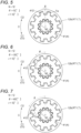
- FIGS. 5 to 7 are diagrams showing positional relationship between the rotor shaft 12b as the first rotary member RT1 and target rotary member T and the lock member 4 in a case where torque toward the circumferential direction first side C1 is transmitted to the rotor shaft 12b.
- FIGS. 8 to 10 are diagrams showing positional relationship between the rotor shaft 12b as the first rotary member RT1 and target rotary member T and the lock member 4 in a case where torque toward the circumferential direction second side C2 is transmitted to the rotor shaft 12b.
- the rotational position sensor 8 is set such that a detected value of the rotational position of the target rotary member T is zero at one of the theoretical lock position P0 of N.
- the rotor shaft 12b shown in FIG. 5 rotates by an amount of backlash toward the circumferential direction first side C1 from the rotational position (theoretical lock position P0) of the rotor shaft 12b shown in FIG. 3 .
- the rotor shaft 12b shown in FIG. 8 rotates by an amount of backlash toward the circumferential direction second side C2 from the rotational position (theoretical lock position P0) of the rotor shaft 12b shown in FIG. 3 .
- the rotational position sensor 8 is a resolver having four poles, the detected rotational position is detected in a range of 0 to 90[°]. Therefore, 85[°] in the present example corresponds to - 5[°] (refer to ⁇ ' shown in FIG. 8 ) in a case where a rotational position sensor that detects a detected rotational position in a range of - 180 to 180[°] is assumed to be used as the rotational position sensor 8.
- the remainder of the division of ⁇ by (360/N) is 5[°]. Furthermore, in the examples shown in FIGS. 8 to 10 , the remainder of the division of ⁇ by (360/N) is 25[°]. Note that, in the examples shown in FIGS. 5 to 10 , "r" represents a remainder of a division of ⁇ by (360/N).
- a remainder of a division of ⁇ by (360/N) is sorted into two groups depending on whether the wheel torque direction Ct is toward the circumferential direction first side C1 or the circumferential direction second side C2.
- the control device 20 determines that the wheel torque direction Ct is toward the circumferential direction first side C1 in a case where the remainder of the division of ⁇ by (360/N) is within a range of 5 ⁇ ⁇ [°].
- the remainder of the division of ⁇ by (360/N) is 5[°], which is within the range of 5 ⁇ ⁇ [°].
- control device 20 determines that the wheel torque direction Ct is toward the circumferential direction second side C2 in a case where the remainder of the division of ⁇ by (360/N) is within a range of 25 ⁇ ⁇ [°].
- the remainder of the division of ⁇ by (360/N) is 25[°], which is within the range of 25 ⁇ ⁇ [°].
- " ⁇ " is a value set in advance on the basis of an error (including an error caused by an installation place of the rotational position sensor 8, an error caused by temperature, or the like, for example) in an output value of the rotational position sensor 8.
- FIG. 11 is a flowchart showing an example of the torque direction determination processing and unlock assist processing by the control device 20.
- Step #1 the control device 20 calculates the remainder of the division of ⁇ by (360/N) (Step #1). Note that "r” in the formula shown in Step #1 in FIG. 11 represents a remainder of the division of ⁇ by (360/N), and “mod” represents an operator of a modulo operation.
- the control device 20 determines whether or not the remainder (r) of the division of ⁇ by (360/N) is within a specified range of r1 ⁇ ⁇ (Step #2). In a case where the remainder of the division of ⁇ by (360/N) is within the specified range of r1 ⁇ ⁇ (Step #2: Yes), the control device 20 determines that the wheel torque direction Ct is toward the circumferential direction first side C1 (Step #3). Note that each of r and r1 is 5[°] in the examples shown in FIGS. 5 to 7 .
- r1 is set to a half value of a rotatable range (angular range) of the target rotary member T (the first rotary member RT1 in the present example) allowed by backlash in the locked state. In a case where r1 is set in this manner, r1 is set to 5[°] when the rotatable range is 10[°].
- the control device 20 determines whether or not the remainder (r) of the division of ⁇ by (360/N) is within a specified range of r2 ⁇ ⁇ (Step #4). In a case where the remainder (r) of the division of ⁇ by (360/N) is within the specified range of r2 ⁇ ⁇ (Step #4: Yes), the control device 20 determines that the wheel torque direction Ct is toward the circumferential direction second side C2 (Step #5).
- each of r and r2 is 25[°] in the examples shown in FIGS. 8 to 10 .
- r2 is set to a value obtained by subtracting a set value of r1 from (360/N).
- Steps #1 to #5 described above correspond to the torque direction determination processing.
- the control device 20 executes the unlock assist processing that causes the rotating electrical machine 1 to output torque in a direction opposite to the wheel torque direction Ct (Step #6).
- the control device 20 determines whether or not the detected rotational position has changed during the unlock assist processing in a direction opposite to the direction of deviation from the theoretical lock position P0 due to backlash (Step #7). In a case where the control device 20 detects that the detected rotational position has changed in a direction opposite to the direction of deviation from the theoretical lock position P0 due to backlash (Step #7: Yes), the control device 20 maintains or reduces an absolute value of torque of the rotating electrical machine 1 (Step #8). For example, in the examples shown in FIGS. 5 to 7 , the control device 20 maintains or reduces the absolute value of the torque of the rotating electrical machine 1 when detecting that the detected rotational position has changed during the unlock assist processing to the circumferential direction second side C2.
- Step #7 the control device 20 returns to Step #6 described above and continues the processing.
- the lock member 4 it is possible to avoid the lock member 4 from being hindered to move by an excessive increase in the absolute value of the torque of the rotating electrical machine 1 in the unlock assist processing, the excessive increase causing an increase in the engagement force between the lock member 4 and the first rotary member RT1.
- the wheel torque direction Ct can be determined by relatively simple arithmetic processing.
- the vehicle drive device 100 includes
- the wheel torque direction Ct is determined on the basis of the direction in which the detected rotational position is deviated from the theoretical lock position P0 due to the backlash.
- torque in a direction to weaken engagement force between the lock member 4 and the first rotary member RT1 can be appropriately output to the rotating electrical machine 1. Therefore, it is possible to appropriately control torque of the rotating electrical machine 1 in a case of unlocking the parking lock mechanism 10.
- the configuration it is possible to eliminate need for various sensors, such as an inclination angle sensor, for determining the wheel torque direction Ct. Therefore, it is easy to simplify and reduce costs for a configuration of the vehicle drive device 100.
- the control device 20 executes the unlock assist processing that causes the rotating electrical machine 1 to output torque in a direction opposite to the wheel torque direction Ct.
- torque in a direction to weaken engagement force between the lock member 4 and the first rotary member RT1 can be appropriately output to the rotating electrical machine 1.
- the backlash is set so as to be greater than the error in the output value of the rotational position sensor 8.
- the error in the output value of the rotational position sensor 8 including an error caused by an installation place of the rotational position sensor 8, an error caused by temperature, or the like for example, can be grasped in advance with an experiment or the like.
- a vehicle drive device (100) includes
- the wheel torque direction (Ct) is determined on the basis of the direction in which the detected rotational position is deviated from the theoretical lock position (P0) due to the backlash.
- torque in a direction to weaken engagement force between the lock member (4) and the first rotary member (RT1) can be appropriately output to the rotating electrical machine (1). Therefore, it is possible to appropriately control torque of the rotating electrical machine (1) in a case of unlocking the parking lock mechanism (10).
- the control device (20) preferably executes unlock assist processing that causes the rotating electrical machine (1) to output torque in a direction opposite to the wheel torque direction (Ct).
- torque in a direction to weaken engagement force between the lock member (4) and the first rotary member (RT1) can be appropriately output to the rotating electrical machine (1).
- a direction along a direction in which the first rotary member (RT1) rotates is preferably defined as a circumferential direction (C),
- the wheel torque direction (Ct) can be determined by relatively simple arithmetic processing.
- the backlash is preferably set so as to be greater than an error in an output value of the rotational position sensor (8).
- the rotational position sensor (8) is preferably set such that a detected value of a rotational position of the target rotary member (T) is zero at one of the theoretical lock position (P0) of N.
- control device (20) in a case where the control device (20) detects that the detected rotational position has changed during the unlock assist processing in a direction opposite to a direction of deviation from the theoretical lock position (P0) due to the backlash, the control device (20) preferably maintains or reduces an absolute value of torque of the rotating electrical machine (1).
- the lock member (4) it is possible to avoid the lock member (4) from being hindered to move by an excessive increase in the absolute value of the torque of the rotating electrical machine (1) in the unlock assist processing, the excessive increase causing an increase in the engagement force between the lock member (4) and the first rotary member (RT1).
- the technology according to the present disclosure can be applied to a vehicle drive device including a rotating electrical machine that functions as a driving force source of wheels, and a parking lock mechanism that selectively restricts rotation of a rotary member that rotates in conjunction with the wheels.
- 100 Vehicle drive device, 1: Rotating electrical machine, 4: Lock member, 412: Second engaging portion (engaging portion), 5: Drive device, 8: Rotational position sensor, 10: Parking lock mechanism, 20: Control device, RT1: First rotary member, RT2: Second rotary member, T: Target rotary member, Ta: Second engaged portion (engaged portion), W: Wheel, P0: Theoretical lock position, P1: Lock position, P2: Unlock position, C: Circumferential direction, and Ct: Wheel torque direction
Landscapes
- Engineering & Computer Science (AREA)
- Mechanical Engineering (AREA)
- General Engineering & Computer Science (AREA)
- Transportation (AREA)
- Power Engineering (AREA)
- Electric Propulsion And Braking For Vehicles (AREA)
Applications Claiming Priority (2)
| Application Number | Priority Date | Filing Date | Title |
|---|---|---|---|
| JP2022154874 | 2022-09-28 | ||
| PCT/JP2023/033691 WO2024070765A1 (fr) | 2022-09-28 | 2023-09-15 | Dispositif d'entraînement de véhicule |
Publications (2)
| Publication Number | Publication Date |
|---|---|
| EP4516567A1 true EP4516567A1 (fr) | 2025-03-05 |
| EP4516567A4 EP4516567A4 (fr) | 2025-09-24 |
Family
ID=90477491
Family Applications (1)
| Application Number | Title | Priority Date | Filing Date |
|---|---|---|---|
| EP23871996.7A Pending EP4516567A4 (fr) | 2022-09-28 | 2023-09-15 | Dispositif d'entraînement de véhicule |
Country Status (5)
| Country | Link |
|---|---|
| US (1) | US12522183B2 (fr) |
| EP (1) | EP4516567A4 (fr) |
| JP (1) | JP7800715B2 (fr) |
| CN (1) | CN119968286A (fr) |
| WO (1) | WO2024070765A1 (fr) |
Family Cites Families (9)
| Publication number | Priority date | Publication date | Assignee | Title |
|---|---|---|---|---|
| JP3454009B2 (ja) * | 1996-04-22 | 2003-10-06 | トヨタ自動車株式会社 | 電気自動車のメカニカルパーキングロック装置 |
| JP3903813B2 (ja) | 2002-03-07 | 2007-04-11 | トヨタ自動車株式会社 | 電気自動車のパーキング抜き振動防止装置 |
| JP4894933B2 (ja) * | 2009-06-04 | 2012-03-14 | 株式会社デンソー | シフトレンジ切換装置、及びパーキングロック装置 |
| JP2016161058A (ja) * | 2015-03-03 | 2016-09-05 | 日産自動車株式会社 | 車両のパークロック装置 |
| JP6585473B2 (ja) * | 2015-11-09 | 2019-10-02 | 株式会社Subaru | 自動駐車制御装置 |
| JP6583299B2 (ja) * | 2017-01-26 | 2019-10-02 | トヨタ自動車株式会社 | ハイブリッド車両の制御装置 |
| KR101996297B1 (ko) * | 2017-12-20 | 2019-07-04 | 한호산업(주) | 전기자동차 변속기용 파킹장치 및 그 고장진단방법 |
| JP2021025551A (ja) * | 2019-07-31 | 2021-02-22 | いすゞ自動車株式会社 | 制御装置及び、制御方法 |
| JP7453122B2 (ja) * | 2020-11-06 | 2024-03-19 | トヨタ自動車株式会社 | シフトバイワイヤシステム |
-
2023
- 2023-09-15 EP EP23871996.7A patent/EP4516567A4/fr active Pending
- 2023-09-15 US US18/871,649 patent/US12522183B2/en active Active
- 2023-09-15 JP JP2024550096A patent/JP7800715B2/ja active Active
- 2023-09-15 WO PCT/JP2023/033691 patent/WO2024070765A1/fr not_active Ceased
- 2023-09-15 CN CN202380069443.3A patent/CN119968286A/zh active Pending
Also Published As
| Publication number | Publication date |
|---|---|
| WO2024070765A1 (fr) | 2024-04-04 |
| CN119968286A (zh) | 2025-05-09 |
| EP4516567A4 (fr) | 2025-09-24 |
| US12522183B2 (en) | 2026-01-13 |
| JP7800715B2 (ja) | 2026-01-16 |
| JPWO2024070765A1 (fr) | 2024-04-04 |
| US20250353474A1 (en) | 2025-11-20 |
Similar Documents
| Publication | Publication Date | Title |
|---|---|---|
| US20130324342A1 (en) | Motor driving force transmission device | |
| JP5648564B2 (ja) | 回転式アクチュエータ | |
| US9077227B2 (en) | Electric motor assembly with electric phasing of rotor segments to reduce back electromotive force | |
| US20130009522A1 (en) | Drive motor for electric vehicle | |
| JP2004052928A (ja) | 回転式アクチュエータ | |
| JP6327137B2 (ja) | 回転式アクチュエータ | |
| JP2006204043A (ja) | 切替制御装置 | |
| US9866157B2 (en) | Method and apparatus for a position sensor for a transmission integrated synchronous motor | |
| US20060232393A1 (en) | Controller for vehicle-mounted component | |
| JP2014177265A (ja) | 駆動装置 | |
| EP4516567A1 (fr) | Dispositif d'entraînement de véhicule | |
| US11814116B2 (en) | Assist mechanism and electric power steering device | |
| JP4363237B2 (ja) | 同期モータ装置 | |
| WO2024034427A1 (fr) | Dispositif d'entraînement de véhicule | |
| JP2023125607A (ja) | 車両用駆動装置 | |
| JP2009159725A (ja) | 駆動装置とその製造方法 | |
| KR100680212B1 (ko) | 전동기 | |
| JP2006223010A (ja) | レゾルバとベアリングの取付構造 | |
| JP2006273295A (ja) | 車両用操舵装置 | |
| JP4185746B2 (ja) | 相対回転状態検知装置 | |
| JP5659588B2 (ja) | ホイール軸受および電動車両駆動装置 | |
| EP3561337B1 (fr) | Commande harmonique à entraînement magnétique | |
| CN114039436A (zh) | 用于旋转电机的转子 | |
| WO2024070764A1 (fr) | Mécanisme de verrouillage de stationnement | |
| JP2015195671A (ja) | 回転機 |
Legal Events
| Date | Code | Title | Description |
|---|---|---|---|
| STAA | Information on the status of an ep patent application or granted ep patent |
Free format text: STATUS: THE INTERNATIONAL PUBLICATION HAS BEEN MADE |
|
| PUAI | Public reference made under article 153(3) epc to a published international application that has entered the european phase |
Free format text: ORIGINAL CODE: 0009012 |
|
| STAA | Information on the status of an ep patent application or granted ep patent |
Free format text: STATUS: REQUEST FOR EXAMINATION WAS MADE |
|
| 17P | Request for examination filed |
Effective date: 20241128 |
|
| AK | Designated contracting states |
Kind code of ref document: A1 Designated state(s): AL AT BE BG CH CY CZ DE DK EE ES FI FR GB GR HR HU IE IS IT LI LT LU LV MC ME MK MT NL NO PL PT RO RS SE SI SK SM TR |
|
| A4 | Supplementary search report drawn up and despatched |
Effective date: 20250825 |
|
| RIC1 | Information provided on ipc code assigned before grant |
Ipc: B60L 15/20 20060101AFI20250819BHEP Ipc: B60T 7/12 20060101ALI20250819BHEP Ipc: F16H 63/34 20060101ALI20250819BHEP |
|
| DAV | Request for validation of the european patent (deleted) | ||
| DAX | Request for extension of the european patent (deleted) |