EP4516575A1 - Dispositif de charge automatic pour charger un véhicule électrique - Google Patents
Dispositif de charge automatic pour charger un véhicule électrique Download PDFInfo
- Publication number
- EP4516575A1 EP4516575A1 EP24187089.8A EP24187089A EP4516575A1 EP 4516575 A1 EP4516575 A1 EP 4516575A1 EP 24187089 A EP24187089 A EP 24187089A EP 4516575 A1 EP4516575 A1 EP 4516575A1
- Authority
- EP
- European Patent Office
- Prior art keywords
- charging
- plug
- holder
- designed
- charging plug
- Prior art date
- Legal status (The legal status is an assumption and is not a legal conclusion. Google has not performed a legal analysis and makes no representation as to the accuracy of the status listed.)
- Pending
Links
Images


Classifications
-
- B—PERFORMING OPERATIONS; TRANSPORTING
- B60—VEHICLES IN GENERAL
- B60L—PROPULSION OF ELECTRICALLY-PROPELLED VEHICLES; SUPPLYING ELECTRIC POWER FOR AUXILIARY EQUIPMENT OF ELECTRICALLY-PROPELLED VEHICLES; ELECTRODYNAMIC BRAKE SYSTEMS FOR VEHICLES IN GENERAL; MAGNETIC SUSPENSION OR LEVITATION FOR VEHICLES; MONITORING OPERATING VARIABLES OF ELECTRICALLY-PROPELLED VEHICLES; ELECTRIC SAFETY DEVICES FOR ELECTRICALLY-PROPELLED VEHICLES
- B60L53/00—Methods of charging batteries, specially adapted for electric vehicles; Charging stations or on-board charging equipment therefor; Exchange of energy storage elements in electric vehicles
- B60L53/30—Constructional details of charging stations
- B60L53/35—Means for automatic or assisted adjustment of the relative position of charging devices and vehicles
- B60L53/37—Means for automatic or assisted adjustment of the relative position of charging devices and vehicles using optical position determination, e.g. using cameras
-
- B—PERFORMING OPERATIONS; TRANSPORTING
- B60—VEHICLES IN GENERAL
- B60L—PROPULSION OF ELECTRICALLY-PROPELLED VEHICLES; SUPPLYING ELECTRIC POWER FOR AUXILIARY EQUIPMENT OF ELECTRICALLY-PROPELLED VEHICLES; ELECTRODYNAMIC BRAKE SYSTEMS FOR VEHICLES IN GENERAL; MAGNETIC SUSPENSION OR LEVITATION FOR VEHICLES; MONITORING OPERATING VARIABLES OF ELECTRICALLY-PROPELLED VEHICLES; ELECTRIC SAFETY DEVICES FOR ELECTRICALLY-PROPELLED VEHICLES
- B60L53/00—Methods of charging batteries, specially adapted for electric vehicles; Charging stations or on-board charging equipment therefor; Exchange of energy storage elements in electric vehicles
- B60L53/10—Methods of charging batteries, specially adapted for electric vehicles; Charging stations or on-board charging equipment therefor; Exchange of energy storage elements in electric vehicles characterised by the energy transfer between the charging station and the vehicle
- B60L53/14—Conductive energy transfer
- B60L53/16—Connectors, e.g. plugs or sockets, specially adapted for charging electric vehicles
-
- B—PERFORMING OPERATIONS; TRANSPORTING
- B60—VEHICLES IN GENERAL
- B60L—PROPULSION OF ELECTRICALLY-PROPELLED VEHICLES; SUPPLYING ELECTRIC POWER FOR AUXILIARY EQUIPMENT OF ELECTRICALLY-PROPELLED VEHICLES; ELECTRODYNAMIC BRAKE SYSTEMS FOR VEHICLES IN GENERAL; MAGNETIC SUSPENSION OR LEVITATION FOR VEHICLES; MONITORING OPERATING VARIABLES OF ELECTRICALLY-PROPELLED VEHICLES; ELECTRIC SAFETY DEVICES FOR ELECTRICALLY-PROPELLED VEHICLES
- B60L53/00—Methods of charging batteries, specially adapted for electric vehicles; Charging stations or on-board charging equipment therefor; Exchange of energy storage elements in electric vehicles
- B60L53/30—Constructional details of charging stations
- B60L53/35—Means for automatic or assisted adjustment of the relative position of charging devices and vehicles
-
- Y—GENERAL TAGGING OF NEW TECHNOLOGICAL DEVELOPMENTS; GENERAL TAGGING OF CROSS-SECTIONAL TECHNOLOGIES SPANNING OVER SEVERAL SECTIONS OF THE IPC; TECHNICAL SUBJECTS COVERED BY FORMER USPC CROSS-REFERENCE ART COLLECTIONS [XRACs] AND DIGESTS
- Y02—TECHNOLOGIES OR APPLICATIONS FOR MITIGATION OR ADAPTATION AGAINST CLIMATE CHANGE
- Y02T—CLIMATE CHANGE MITIGATION TECHNOLOGIES RELATED TO TRANSPORTATION
- Y02T10/00—Road transport of goods or passengers
- Y02T10/60—Other road transportation technologies with climate change mitigation effect
- Y02T10/70—Energy storage systems for electromobility, e.g. batteries
-
- Y—GENERAL TAGGING OF NEW TECHNOLOGICAL DEVELOPMENTS; GENERAL TAGGING OF CROSS-SECTIONAL TECHNOLOGIES SPANNING OVER SEVERAL SECTIONS OF THE IPC; TECHNICAL SUBJECTS COVERED BY FORMER USPC CROSS-REFERENCE ART COLLECTIONS [XRACs] AND DIGESTS
- Y02—TECHNOLOGIES OR APPLICATIONS FOR MITIGATION OR ADAPTATION AGAINST CLIMATE CHANGE
- Y02T—CLIMATE CHANGE MITIGATION TECHNOLOGIES RELATED TO TRANSPORTATION
- Y02T10/00—Road transport of goods or passengers
- Y02T10/60—Other road transportation technologies with climate change mitigation effect
- Y02T10/7072—Electromobility specific charging systems or methods for batteries, ultracapacitors, supercapacitors or double-layer capacitors
-
- Y—GENERAL TAGGING OF NEW TECHNOLOGICAL DEVELOPMENTS; GENERAL TAGGING OF CROSS-SECTIONAL TECHNOLOGIES SPANNING OVER SEVERAL SECTIONS OF THE IPC; TECHNICAL SUBJECTS COVERED BY FORMER USPC CROSS-REFERENCE ART COLLECTIONS [XRACs] AND DIGESTS
- Y02—TECHNOLOGIES OR APPLICATIONS FOR MITIGATION OR ADAPTATION AGAINST CLIMATE CHANGE
- Y02T—CLIMATE CHANGE MITIGATION TECHNOLOGIES RELATED TO TRANSPORTATION
- Y02T90/00—Enabling technologies or technologies with a potential or indirect contribution to GHG emissions mitigation
- Y02T90/10—Technologies relating to charging of electric vehicles
- Y02T90/14—Plug-in electric vehicles
Definitions
- the invention relates to a charging device for charging an electric vehicle with electrical energy by means of a charging cable with a charging plug arranged at the end, which can be connected to a charging connection on the electric vehicle to be charged.
- Electric vehicles also called electrically powered vehicles
- the first applications will be autonomous taxis and shuttle vehicles, for example.
- the utilization of these autonomous vehicles is a decisive factor for the profitability of the services, so downtimes due to charging must be minimized as much as possible. This is done by appropriate fast charging stations with direct current or alternating current.
- a person carries out the charging process by connecting a charging cable or charging plug from the fast charging station to a charging port on the electric vehicle. Possible movements of the vehicle during the charging process, for example by people getting in or out or by loading or unloading payloads, are compensated for by the flexible charging cable.
- the invention is based on the object of providing an improved charging device for charging an electric vehicle, in particular an autonomously driving one.
- the charging device for charging an electric vehicle with electrical energy, by means of a charging cable with a charging plug arranged at the end, which can be connected to a charging connection on the electric vehicle to be charged, is characterized by a plug holder which is designed to automatically connect the charging plug to the charging connection or, in the connected state, to automatically release it from the charging connection, in particular to pull it off or decouple it.
- a charging device in particular an autonomous rapid charging device, with such an additional plug holder enables automated charging of the electric vehicle.
- the invention enables the charging plug to be automatically connected to a charging port for charging, to be automatically released or let go of the plug holder during charging and, after the charging process has ended, to be automatically found and picked up by the plug holder, in particular gripped, and to be released, in particular pulled off, from the charging port.
- a charging device is understood to mean in particular a charging station, for example a rapid charging station.
- the charging station can be connected to a power grid on the one hand and to the charging cable on the other.
- the charging station is designed to be adjustable in at least one, preferably in two, three or more spatial directions.
- the plug holder is designed to hold an unplugged charging plug on the plug holder.
- the Plug holder must be designed to hold the charging plug on the plug holder when connecting it to the charging port.
- the plug holder can be designed to release the plugged-in charging plug after the charging plug has been connected to the charging port, in particular to let go of it.
- the charging plug is thus decoupled from the plug holder and remains plugged into this charging port during charging.
- the charging plug may be connected to the charging device via the flexible charging cable.
- the plug holder can be configured to both find the charging plug plugged into the charging port and to catch, grip and detach it from the charging port.
- the plug holder is configured to automatically find, catch, grip and detach the plugged charging plug from the charging port.
- the plug holder can comprise a coupling device that is designed to detachably hold and/or fix the charging plug.
- the coupling device can be designed to hold the charging plug by means of a positive connection and/or a frictional connection.
- the charging plug can be clamped, tensioned and/or held magnetically on the coupling device.
- the coupling device can be designed, for example, as a clamping unit, tensioning unit or a magnet unit.
- the coupling device and the charging plug comprise elements that correspond to one another, in particular clamping elements, tensioning elements and/or magnet elements.
- the coupling device can be designed as a retraction mechanism, in particular a
- the cable pull mechanism can be designed, for example, with a cable pull on which the charging plug is held loosely and flexibly on the one hand and which is retractably mounted on the coupling device on the other hand, and a centering unit, in particular a centered and positive-locking catching device, in particular a catching funnel, a catching tray or the like.
- the cable pull ensures that the charging plug is held securely.
- the cable pull offers flexibility.
- the centering unit aligns the charging plug when it is picked up and moves it into the centering unit and holds it aligned and positively and/or force-fitting in the centering unit, for example in a corresponding holder, also called a catching holder.
- the plug holder can comprise a monitoring unit that is designed to monitor and/or locate a plugged-in charging plug with regard to its plug position.
- a camera or a camera system can be used as a monitoring unit to find or find the charging plug.
- Two separate monitoring units can also be provided, with one monitoring unit for finding a charging connection when it is connected to an electric vehicle to be charged and another monitoring unit for tracking any possible movement of the plugged-in charging plug when the electric vehicle is being charged.
- the monitoring unit for locating the charging port can, due to the larger adjustment movement, in particular have a larger detection range than the other Monitoring unit to track the movement of the plugged-in charging plug.
- the monitoring units can be of different types.
- the monitoring unit for locating the charging connection and thus for monitoring a longer distance can be designed as a camera.
- the monitoring unit for monitoring the tracking of the movements of the plugged-in charging plug and thus for monitoring short distances can be, for example, a proximity sensor, in particular a capacitive proximity sensor, an inductive proximity sensor, a radio-based monitoring unit but also a camera or the like.
- At least one monitoring unit in particular a camera, can, for example, detect and recognize a shape, a marking or a pattern on the charging plug itself. Additionally or alternatively, another monitoring unit, in particular a camera, can detect and recognize the charging connection on the vehicle. Using an algorithm, for example, with a camera as the monitoring unit, camera images and optionally their distortions are determined and based on these, the plug position of the charging plug, in particular the plugged in one, or the connection position of a free charging connection for automatically connecting the charging plug to the free charging connection is determined. Alternatively, sensor values from corresponding sensors are recorded and used.
- the respective position in particular the plug position and/or the connection position, can be converted into coordinates, based on which the plug holder is then moved and aligned to automatically connect the charging plug to the free charging connection or to find and release, in particular to pull off, the plugged charging plug from the charging connection.
- the charging device can comprise an adjustment device, for example linear actuators, angle actuators, swivel joints and/or ball joints.
- an adjustment device for example linear actuators, angle actuators, swivel joints and/or ball joints.
- the plug holder can follow the charging plug and its position during a charging process (also called fine adjustment, which is intended to follow a movement of the plugged-in charging plug during charging of the electric vehicle).
- the plug holder can be moved in the direction of the charging port and aligned with respect to the charging port by means of the adjustment device before a charging process (also called coarse adjustment, which is intended for finding the non-standard position of the charging port on the electric vehicle).
- a charging process also called coarse adjustment, which is intended for finding the non-standard position of the charging port on the electric vehicle.
- the plug holder can be moved by means of the adjustment device after a charging process in the direction of the charging plug to accommodate it and can be moved away from the charging connection to release the charging plug (also called feed movement).
- the plug-in holder can be arranged and attached to a movable unit of the adjustment device.
- the plug-in holder itself can be mounted so that it can move.
- the adjustment device can move the plug holder accordingly. Moving or adjusting the plug holder ensures that when the electric vehicle moves while charging the electric vehicle, the plug holder automatically follows the plug position of the charging plug and/or that the plug holder is aligned with the charging plug that is not plugged in but is connected to the charging device.
- the charging plug fixed in the plug holder can be aligned with respect to the charging port.
- the charging plug When the charging process is completed, the charging plug can be picked up in the correct position by means of the coupling device, for example a clamping unit or the like, due to the automatic tracking of the plug holder and can be held and fixed to the plug holder.
- the coupling device for example a clamping unit or the like
- the plug holder can be designed to be movable between a starting position and the plug position.
- the plug holder is placed in a starting position on the charging device before charging.
- the plug holder can first be automatically aligned with respect to the charging port and then placed in the plug position to automatically connect the charging plug to the charging port on the electric vehicle.
- the plug holder can be returned to the starting position.
- Such adjustability and mobility of the plug holder when the charging plug is not plugged in and thus when the charging plug is held on the plug holder means that the plug holder can be moved freely.
- the electric vehicle with the plugged-in charging plug can be moved freely due to the flexible charging cable.
- movements resulting from, for example, loading or unloading the electric vehicle and/or people getting in or out during the charging process of the electric vehicle and when the charging plug is plugged in can be flexibly compensated for.
- the Forces resulting from small movements of the electric vehicle, which act on the coupling between the plugged-in charging plug and charging device are reduced or even avoided.
- the charging device 2 is designed as an autonomous charging station for charging the electric vehicle 1.
- the electric vehicle 1 is, for example, an autonomously driving electric vehicle that automatically drives up to the charging device 2 for charging.
- the charging device 2 in particular the autonomous charging station, comprises a drag chain arrangement 4 for the flexible routing of a set 3 of cables (hereinafter referred to as cable set 3) from a supply connection or power connection (not shown), in particular a ground connection, of a nearby or distant charging station (not shown in detail) to a charging connection 5 of the electric vehicle 1.
- the charging device 2 with the drag chain arrangement 4 is designed as a charging robot, by means of which a plug holder 8 arranged on the drag chain arrangement 4 can be variably guided, in particular in several spatial directions 7.1 to 7.3, in the direction of the charging port 5 can be moved and/or aligned with respect to the charging port 5.
- the electric vehicle 1 comprises, for example, a charging plug socket as a charging connection 5.
- the cable set 3 comprises a charging plug 6 at its end pointing towards the electric vehicle 1, which is designed to be coupled to the charging connection 5.
- the charging plug 6 is shown plugged into its plug position 20 in the charging connection 5.
- the drag chain arrangement 4 (also called cable guide arrangement) is in particular designed to move or transport the cable set 3 flexibly in the direction of the charging connection 5 in at least one spatial direction 7.1 to 7.3 (also called transport direction) and to align it with respect to the charging connection 5 of the electric vehicle 1.
- the cable set 3 can be flexibly moved or transported in a first spatial direction 7.1 in the longitudinal direction x, in a second spatial direction 7.2 in the vertical direction z and/or in a third spatial direction 7.3 in the transverse direction y over a corresponding length or a corresponding distance up to the charging connection 5 of the electric vehicle 1 that has autonomously approached the charging device 2.
- the charging device 2 is designed in such a way that the charging plug 6 arranged at the end of the cable set 3 is automatically moved to the position of the charging connection 5 of the electric vehicle 1 and is aligned there with respect to the charging connection 5 and introduced, in particular plugged, into the charging connection 5. After the charging process has ended, the charging plug 6 can be automatically released, in particular pulled or removed, from the charging connection 5 by means of the charging device 2.
- the charging device 2 comprises a plug holder 8, which is described in more detail below in the Figures 3 to 10 described.
- the charging device 2 can be used universally for various electric vehicles 1, since the cable set 3 with the charging plug 6 can be transported to the respective, usually non-standardized position of the charging connection 5 on electric vehicles 1.
- the charging connection 5 can be provided on the electric vehicle 1 at the front, on the side or at the back.
- the autonomous charging device 2 designed as a charging robot is in particular set up to move the charging plug 6 automatically, for example indirectly by means of the drag chain arrangement 4, in the direction of an identified charging connection 5 of an electric vehicle 1 to be charged, to align it with respect to this charging connection 5 and to insert it into it.
- the charging device 2 is designed to automatically move the charging plug 6 to the charging port 5 and insert it into it only in the transverse direction y.
- the charging device 2 can be designed to automatically move the charging plug 6 in the longitudinal direction x to adjust the charging plug 6 in the direction of the charging port 5 and in the transverse direction y to insert the charging plug 6 into the charging port 5.
- the charging device 2 can be designed to automatically move the charging plug 6 in the vertical direction z.
- the charging device 2 is designed to move the charging plug 6 in three spatial directions 7.1 to 7.3 in the direction of the charging connection 5.
- the drag chain arrangement 4 comprises, for each spatial direction 7.1 to 7.3, an associated drag chain unit 4.1 to 4.3 and the plug holder 8 for the charging plug 6, for automatically picking up, in particular gripping, fixing and optionally releasing or releasing the charging plug 6.
- a first drag chain unit 4.1 is designed to move the cable set 3 back and forth in the longitudinal direction x.
- a second drag chain unit 4.2 is designed to move the cable set 3 up and down in the vertical direction z.
- a third drag chain unit 4.3 is designed to move the cable set 3 back and forth in the transverse direction y.
- the third drag chain unit 4.3 can be arranged on the second drag chain unit 4.2 or the first drag chain unit 4.1.
- the second drag chain unit 4.2 can be arranged on the first drag chain unit 4.1 or on the third drag chain unit 4.3.
- the connector holder 8 is arranged on the third drag chain unit 4.3.
- the respective drag chain units 4.1 to 4.3 are arranged and mounted so as to be movable relative to one another.
- the second drag chain unit 4.2 is attached to the first drag chain unit 4.1 for a common adjustment in the longitudinal direction x.
- the third drag chain unit 4.3 is attached to the second drag chain unit 4.2 for an adjustment in the vertical direction z and is coupled via this second drag chain unit 4.2 to the first drag chain unit 4.1 for an adjustment in the longitudinal direction x.
- the third drag chain unit 4.3 is also arranged to be movable relative to the second drag chain unit 4.2 and to the first drag chain unit 4.1 for an adjustment in the transverse direction y.
- the plug holder 8 is designed to insert the charging plug 6 into the charging connection 5.
- the third drag chain unit 4.3 to which the plug holder 8 is attached, is movable relative to the second drag chain unit 4.2 and the first drag chain unit 4.1 for adjustment in Transverse direction y.
- the rigid or fixed connector holder 8 is movably arranged on the third drag chain unit 4.3, for example by means of a linear actuator, an angle actuator, a rotary joint, a ball joint or the like.
- the charging plug 6 is still firmly or rigidly connected to the plug holder 8. To compensate for slight vehicle movements, the plug holder 8 is designed to release the charging plug 6 so that it is plugged into the charging connection 5 on the one hand and is connected to the charging device 2 designed as a charging station on the other.
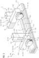
- Figure 2 shows schematically in perspective the loading device 2 according to Figure 1 .
- Figure 2 shows the charging device 2, in particular the first drag chain unit 4.1, in its two end positions 9.1, 9.2, between which the charging plug 6 can be moved to any position in the longitudinal direction x in the first spatial direction 7.1. Furthermore, the Figure 2 the second drag chain unit 4.2 in its two end positions 9.3 and 9.4, between which the charging plug 6 can be moved to any position in the vertical direction z in the second spatial direction 7.2. The third drag chain unit 4.3 is also shown in its two end positions 9.5 and 9.6, between which the charging plug 6 can be moved to any position in the transverse direction y in the third spatial direction 7.3.
- the plug holder 8 is moved in the direction of the charging port 5 by means of the drag chain arrangement 4 and, when the longitudinal position of the charging port 5 is reached, is aligned relative to this charging port 5 in order to then automatically insert the charging plug 6 into the charging port 5 or to release or decouple it from it.
- the plug holder 8 itself can be movably mounted and relative to the charging port 5 (shown in Figure 1 ) and inserted into the charging port 5 or removed or uncoupled from it.
- the respective drag chain unit 4.1 to 4.3 comprises a housing 10.1 to 10.3.
- the plug holder 8 is arranged in a longitudinally adjustable manner in a longitudinal recess 11 of the housing 10.1 of the first drag chain unit 4.1 via the movably coupled drag chain units 4.2 and 4.3.
- the third drag chain unit 4.3 is arranged in a vertical recess 12 of the housing 10.2 of the second drag chain unit 4.2 so as to be vertically adjustable.
- the third drag chain unit 4.3 can additionally be arranged to be movable in the transverse direction y relative to the second drag chain unit 4.2 and/or the first drag chain unit 4.1.
- the housing 10.3 can comprise a transverse recess in the direction of the second drag chain unit 4.2 in a manner not shown in more detail.
- Each of the drag chain units 4.1 to 4.3 can comprise an associated adjustment device 18, for example a rail system, a guide system with a carriage or the like.
- the adjustment device 18 can comprise, for example, linear actuators, angle actuators, rotary joints and/or ball joints.
- the drag chain units 4.1 to 4.3 can be adjusted independently of one another or dependently of one another into one or more of the Spatial directions 7.1 to 7.3 can be adjusted, whereby the plug holder 8 connected to the drag chain unit 4.3 can move the charging plug 6 before a charging process, during a charging process and/or after a charging process and/or track the position of a released and plugged charging plug 6 and/or align the charging plug 6 with respect to the charging connection 5.
- the respective adjustment device 18 can comprise a stationary unit 13, for example a fixed rail or a fixed guide or a fixed joint, and a movable unit 14, for example a movable rail or a carriage or a movable joint.
- the respective adjustment device 18, in particular its movable unit 14, is coupled in terms of movement to a drive (not shown in detail), in particular a motor, for example an electric motor, or the like.
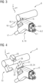
- Figure 3 shows schematically in perspective an example of the plug holder 8 with a held charging plug 6, in particular fixed to the plug holder 8 in a form-fitting and/or force-fitting manner.
- the plug holder 8 is set up to automatically connect the charging plug 6 to the charging port 5 on the electric vehicle 1 (in Figure 1 shown).
- the plug holder 8 is designed so that the charging plug 6 can be automatically detached/released from the plug holder 8, in particular when the charging plug 6 is plugged into the charging port 5.
- the plug holder 8 can be configured to automatically release and decouple the charging plug 6 from the charging port 5. To automatically release and decouple the charging plug 6 from the charging port 5, the charging plug 6 is held on the plug holder 8 and releasably fixed.
- the plug holder 8 is designed to hold the unplugged charging plug 6 on the plug holder 8.
- the plug holder 8 can be designed to continue to hold and fix the charging plug 6 on the plug holder 8 when connecting it to the charging port 5. In other words: When the plug holder 8 is moved in the direction of the charging port 5 for connection, the charging plug 6 is taken along and automatically inserted into the charging port 5.
- the plug holder 8 comprises a coupling device 15 which is designed to releasably hold and/or releasably fix the charging plug 6.
- the coupling device 15 can be designed to hold and releasably fix the charging plug 6 to the plug holder 8 in a form-fitting and/or force-fitting manner.
- the coupling device 15 can be designed to hold and releasably fix the charging plug 6 to the plug holder 8 in a clamped, tensioned and/or magnetic manner or by means of a cable pull, in particular a safety cable pull, or the like.
- the coupling device 15 can be designed, for example, as a magnet unit 16, which has at least one magnet element 16.1 on the plug holder 8 and a counter magnet element 16.2 on the charging plug 6. To release the charging plug 6 from the plug holder 8, the magnet element 16.1 and the counter magnet element 16.2 can be controlled and activated or deactivated accordingly.
- the charging plug 6 has at least one charging plug contact 6.1 for a charging cable 17 comprising the set 3 of cables (shown in Figure 1 ), optionally the charging plug 6 can have additional plug contacts 6.2, 6.3 for example for protective conductors, communication lines, signal lines, control lines, supply lines or the like. Cables that are additionally provided in set 3 of cables.
- the detachable coupling of plug holder 8 and charging plug 6 makes it possible to avoid damage as a result of slight vehicle movements when charging the electric vehicle 1, compared to known fixed couplings of plug holder 8 and charging plug 6, since these movements can be compensated due to the decoupling.
- FIG 3 shows the charging plug 6 in its initial position, in which the charging plug 6 is held and fixed to the plug holder 8.
- the adjustment device(s) 18 of the drag chain arrangement 4 can move the plug holder 8 in particular between the starting position in which the charging plug 6 is releasably fixed and releasably held on the plug holder 8, and the plug position 20 in which the charging plug 6 is inserted into the charging connection 5 (shown in Figure 1 ), move accordingly.
- FIG 4 shows schematically another example of the plug holder 8 with alternative detachable coupling device 15' for the charging plug 6, which is shown in the released or released position. This means that the Charging plug 6 is detached and released from the plug holder 8.
- the coupling device 15' is designed, for example, as a clamping unit 21 with adjustable clamping elements 22, in particular clamping arms, clamping hooks or the like, which, for example, enable a positive connection with the opposite side.
- the charging plug 6 comprises a clamping bracket 24 as a counter-clamping element 23.
- the plug holder 8 can comprise a monitoring unit 25 which is designed to monitor a plugged charging plug 6 with regard to its plug position 20 (shown in Figure 1 ) to monitor and/or locate.
- the monitoring unit 25 can be at least one camera 26.
- monitoring units 25 for example sensors for determining the position of the charging plug 6 and/or the free charging port 5, can be provided.
- the charging cable 17 (shown in Figure 3 ) is held largely on the charging device 2 designed as a charging station or charging robot. As a result, small vehicle movements when charging the electric vehicle 1 can be compensated for by the freely hanging charging cable 17.
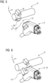
- Figure 5 shows schematically another example of the plug holder 8 with another alternative detachable coupling device 15'' for the charging plug 6, which is placed in a free or released position.
- the coupling device 15'' is arranged, for example, as a clamping unit 27 with a clamping bolt 28 on the plug holder 8 and a clamping receptacle 29 on the charging plug 6.
- coupling devices 15, 15' and 15'' can also be provided, such as a gripper, a zero-point clamping system, a locking pin, a magnetic lock or the like.
- Figure 5 also shows the camera 26 as a monitoring unit 25 for tracking the movement of a plugged-in charging plug 6.
- Figure 6 shows a schematic perspective view of the plug holder 8 with the charging plug 6 fixed to it.
- the charging plug 6 is held and fixed in its initial position on the plug holder 8 by means of the coupling device 15. In this coupled position, the "unplugged" charging plug 6 can be aligned with respect to the charging connection 5 by means of the movable plug holder 8 and can be automatically plugged into it.
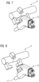
- FIG 7 shows schematically in perspective the plug holder 8 with the charging plug 6 released after coupling with the charging connection 5 (not shown here for better clarity, but in Figures 1 and 2 shown).
- the plug holder 8 is designed to release or let go of the plugged-in charging plug 6 after the charging plug 6 has been connected to the charging connection 5.
- FIG 8 shows schematically in perspective the plug holder 8 with the charging plug 6 released and thus free.
- the charging plug 6 is decoupled from the plug holder 8 and is held in the charging connection 5 (not shown) during charging.
- the charging plug 6 can additionally hang on the safety cable.
- FIG 9 shows schematically in perspective the plug holder 8 after charging and when catching or retrieving the battery still connected to the charging connector 5 (shown in Figure 1 ) plugged-in charging plug 6.
- the monitoring unit 25 which is designed as a camera 26, for example, a possible movement of the charging plug 6 which is uncoupled from the plug holder 8 and plugged into the charging connection 5 is monitored and tracked. If such a movement occurs, the plug holder 8 is automatically guided in the direction of the plugged-in charging plug 6 by means of the adjustment device 18 and aligned in relation to this plugged-in charging plug 6 - this process is also called finding and recapturing.
- the charging plug 6 is then grasped by the plug holder 8, in particular the coupling device 15, and pulled off the charging connection 5 and thus uncoupled from it.
- Figure 10 shows schematically in perspective the plug holder 8 with the charging plug 6 re-fixed.
- the charging plug 6 After gripping the charging plug 6 and uncoupling the charging plug 6 from the charging connection 5, the charging plug 6 is releasably connected to the plug holder 8 again by means of the coupling device 15.
Landscapes
- Engineering & Computer Science (AREA)
- Power Engineering (AREA)
- Transportation (AREA)
- Mechanical Engineering (AREA)
- Charge And Discharge Circuits For Batteries Or The Like (AREA)
- Electric Propulsion And Braking For Vehicles (AREA)
Applications Claiming Priority (1)
| Application Number | Priority Date | Filing Date | Title |
|---|---|---|---|
| DE102023208391.4A DE102023208391A1 (de) | 2023-08-31 | 2023-08-31 | Ladevorrichtung zum Laden eines Elektrofahrzeugs |
Publications (1)
| Publication Number | Publication Date |
|---|---|
| EP4516575A1 true EP4516575A1 (fr) | 2025-03-05 |
Family
ID=91856243
Family Applications (1)
| Application Number | Title | Priority Date | Filing Date |
|---|---|---|---|
| EP24187089.8A Pending EP4516575A1 (fr) | 2023-08-31 | 2024-07-08 | Dispositif de charge automatic pour charger un véhicule électrique |
Country Status (3)
| Country | Link |
|---|---|
| US (1) | US20250074235A1 (fr) |
| EP (1) | EP4516575A1 (fr) |
| DE (1) | DE102023208391A1 (fr) |
Citations (4)
| Publication number | Priority date | Publication date | Assignee | Title |
|---|---|---|---|---|
| DE102015213160A1 (de) * | 2015-07-14 | 2017-01-19 | Volkswagen Aktiengesellschaft | Roboter und Verfahren zum automatisierten Stecken eines Ladesteckers |
| DE102016014463A1 (de) * | 2016-12-05 | 2018-06-07 | Kuka Roboter Gmbh | Versorgung eines Kraftfahrzeugs mittels eines Robotersystems |
| WO2020084111A2 (fr) * | 2018-10-26 | 2020-04-30 | Kuka Deutschland Gmbh | Dispositif de charge automatique d'un véhicule, notamment d'un véhicule électrique |
| EP3758977B1 (fr) * | 2018-03-02 | 2023-06-07 | KUKA Aktiengesellschaft | Effecteur terminal, équipement électrique de charge et procédé |
Family Cites Families (6)
| Publication number | Priority date | Publication date | Assignee | Title |
|---|---|---|---|---|
| DE102018104670A1 (de) * | 2018-03-01 | 2019-09-05 | Volkswagen Aktiengesellschaft | Greifvorrichtung für ein Objekt, Laderoboter mit Greifvorrichtung |
| DE102019203955B4 (de) * | 2019-03-22 | 2025-02-13 | Volkswagen Ag | Vorrichtung zum automatischen Laden eines Elektrofahrzeugs |
| DE102019210042A1 (de) * | 2019-07-08 | 2021-01-14 | Kuka Deutschland Gmbh | Automatisiertes Verbinden von einem Ladestecker mit einer Ladeschnittstelle eines Fahrzeugs |
| DE102020202533A1 (de) * | 2020-02-27 | 2021-09-02 | Siemens Aktiengesellschaft | Ladesystem und Verfahren zum autonomen Laden eines Elektrofahrzeugs |
| DE102020111332A1 (de) * | 2020-04-27 | 2021-10-28 | Innogy Se | Laderobotor für ein Elektrofahrzeug |
| US11718195B2 (en) * | 2020-05-08 | 2023-08-08 | ABB E-mobility B.V. | Automatic electric vehicle charging device |
-
2023
- 2023-08-31 DE DE102023208391.4A patent/DE102023208391A1/de active Pending
-
2024
- 2024-07-08 EP EP24187089.8A patent/EP4516575A1/fr active Pending
- 2024-09-03 US US18/822,668 patent/US20250074235A1/en active Pending
Patent Citations (4)
| Publication number | Priority date | Publication date | Assignee | Title |
|---|---|---|---|---|
| DE102015213160A1 (de) * | 2015-07-14 | 2017-01-19 | Volkswagen Aktiengesellschaft | Roboter und Verfahren zum automatisierten Stecken eines Ladesteckers |
| DE102016014463A1 (de) * | 2016-12-05 | 2018-06-07 | Kuka Roboter Gmbh | Versorgung eines Kraftfahrzeugs mittels eines Robotersystems |
| EP3758977B1 (fr) * | 2018-03-02 | 2023-06-07 | KUKA Aktiengesellschaft | Effecteur terminal, équipement électrique de charge et procédé |
| WO2020084111A2 (fr) * | 2018-10-26 | 2020-04-30 | Kuka Deutschland Gmbh | Dispositif de charge automatique d'un véhicule, notamment d'un véhicule électrique |
Also Published As
| Publication number | Publication date |
|---|---|
| US20250074235A1 (en) | 2025-03-06 |
| DE102023208391A1 (de) | 2025-03-06 |
Similar Documents
| Publication | Publication Date | Title |
|---|---|---|
| DE102019203955B4 (de) | Vorrichtung zum automatischen Laden eines Elektrofahrzeugs | |
| DE102018104759A1 (de) | Verfahren und Vorrichtung zum selbsttätigen Verbinden eines Aufladeanschlusses mit einer Aufladeanschlussaufnahme eines Fahrzeugs, insbesondere eines Landfahrzeugs | |
| EP2909059B1 (fr) | Dispositif de charge d'un véhicule électrique à une borne de recharge | |
| DE102012216980B4 (de) | Von einem Roboter bediente Fahrzeugladestation | |
| EP3528999B1 (fr) | Procédé de chargement pour une machine-outil et dispositif de transfert d'outil | |
| DE102011114321B4 (de) | Steckereinrichtung, Steckeraufnahme und System zur elektrischen Kopplung eines Fahrzeugs mit einer Ladestation sowie entsprechendes Verfahren | |
| EP0440955B1 (fr) | Dispositif pour le montage automatique de câbles électriques avec pièces de connexion dans des boîtiers de prise | |
| DE102017205594A1 (de) | Robotervorrichtung zum Herstellen einer Ladeverbindung zwischen einer Ladevorrichtung und einer Energiespeichereinheit eines Kraftfahrzeugs | |
| DE102017128295A1 (de) | Verfahren für die elektrische Verkabelung elektronischer Komponenten im Schaltanlagenbau und eine entsprechende Anordnung | |
| WO2013030265A2 (fr) | Dispositif pour établir et couper automatiquement une connexion de charge pour un véhicule rechargeable | |
| EP3974119A1 (fr) | Dispositif automatisé de raccordement de prises | |
| EP3119565A1 (fr) | Dispositif de montage pour le remplacement d'une pointe de préhension appartenant à un doigt de préhension pour un système robotique | |
| DE102016207767A1 (de) | Automatisches Stecken eines Ladesteckers für ein Elektrofahrzeug | |
| EP3628579A1 (fr) | Dispositif d'entraînement pour une bicyclette électrique pourvue de connecteur enfichable de moteur pivotant | |
| EP3820731B1 (fr) | Dispositif de charge pour charger une batterie d'un véhicule à moteur à commande électrique | |
| EP3739697B1 (fr) | Dispositif ainsi que procédé de confection automatique d'une paire de lignes | |
| DE102014117566B4 (de) | Automatisiert verbindbare Steckverbinderanordnung, Verfahren zum automatisierten Verbinden einer Steckverbinderanordnung und Verfahren zum automatisierten Lösen einer Steckverbinderanordnung | |
| EP3974121A1 (fr) | Dispositif de fabrication automatisée d'un connecteur enfichable | |
| EP4516575A1 (fr) | Dispositif de charge automatic pour charger un véhicule électrique | |
| DE102018003467A1 (de) | Autonomes Parken und Laden in begrenzten Bereichen | |
| EP1868238A2 (fr) | Dispositif de serrage pour une tranche de silicium | |
| DE102023208393A1 (de) | Ladevorrichtung zum Laden eines Elektrofahrzeugs | |
| DE102016013678B4 (de) | System und Verfahren zum automatisierten Konfektionieren eines Leitungssatzes | |
| DE102019007173A1 (de) | Ladevorrichtung und Verfahren zum elekrtischen Laden eines Fahrzeugs | |
| DE102020120455A1 (de) | Dockingstation für und mit Roboteranlage |
Legal Events
| Date | Code | Title | Description |
|---|---|---|---|
| PUAI | Public reference made under article 153(3) epc to a published international application that has entered the european phase |
Free format text: ORIGINAL CODE: 0009012 |
|
| STAA | Information on the status of an ep patent application or granted ep patent |
Free format text: STATUS: THE APPLICATION HAS BEEN PUBLISHED |
|
| AK | Designated contracting states |
Kind code of ref document: A1 Designated state(s): AL AT BE BG CH CY CZ DE DK EE ES FI FR GB GR HR HU IE IS IT LI LT LU LV MC ME MK MT NL NO PL PT RO RS SE SI SK SM TR |
|
| STAA | Information on the status of an ep patent application or granted ep patent |
Free format text: STATUS: REQUEST FOR EXAMINATION WAS MADE |
|
| 17P | Request for examination filed |
Effective date: 20250820 |