EP4516605A2 - Système de freinage et procédé de commande d'un système de freinage - Google Patents
Système de freinage et procédé de commande d'un système de freinage Download PDFInfo
- Publication number
- EP4516605A2 EP4516605A2 EP25150506.1A EP25150506A EP4516605A2 EP 4516605 A2 EP4516605 A2 EP 4516605A2 EP 25150506 A EP25150506 A EP 25150506A EP 4516605 A2 EP4516605 A2 EP 4516605A2
- Authority
- EP
- European Patent Office
- Prior art keywords
- brake
- pressure
- supply unit
- pressure supply
- wheel
- Prior art date
- Legal status (The legal status is an assumption and is not a legal conclusion. Google has not performed a legal analysis and makes no representation as to the accuracy of the status listed.)
- Pending
Links
Images




Classifications
-
- B—PERFORMING OPERATIONS; TRANSPORTING
- B60—VEHICLES IN GENERAL
- B60T—VEHICLE BRAKE CONTROL SYSTEMS OR PARTS THEREOF; BRAKE CONTROL SYSTEMS OR PARTS THEREOF, IN GENERAL; ARRANGEMENT OF BRAKING ELEMENTS ON VEHICLES IN GENERAL; PORTABLE DEVICES FOR PREVENTING UNWANTED MOVEMENT OF VEHICLES; VEHICLE MODIFICATIONS TO FACILITATE COOLING OF BRAKES
- B60T17/00—Component parts, details, or accessories of power brake systems not covered by groups B60T8/00, B60T13/00 or B60T15/00, or presenting other characteristic features
- B60T17/18—Safety devices; Monitoring
- B60T17/22—Devices for monitoring or checking brake systems; Signal devices
- B60T17/221—Procedure or apparatus for checking or keeping in a correct functioning condition of brake systems
-
- B—PERFORMING OPERATIONS; TRANSPORTING
- B60—VEHICLES IN GENERAL
- B60T—VEHICLE BRAKE CONTROL SYSTEMS OR PARTS THEREOF; BRAKE CONTROL SYSTEMS OR PARTS THEREOF, IN GENERAL; ARRANGEMENT OF BRAKING ELEMENTS ON VEHICLES IN GENERAL; PORTABLE DEVICES FOR PREVENTING UNWANTED MOVEMENT OF VEHICLES; VEHICLE MODIFICATIONS TO FACILITATE COOLING OF BRAKES
- B60T17/00—Component parts, details, or accessories of power brake systems not covered by groups B60T8/00, B60T13/00 or B60T15/00, or presenting other characteristic features
- B60T17/18—Safety devices; Monitoring
- B60T17/22—Devices for monitoring or checking brake systems; Signal devices
-
- B—PERFORMING OPERATIONS; TRANSPORTING
- B60—VEHICLES IN GENERAL
- B60T—VEHICLE BRAKE CONTROL SYSTEMS OR PARTS THEREOF; BRAKE CONTROL SYSTEMS OR PARTS THEREOF, IN GENERAL; ARRANGEMENT OF BRAKING ELEMENTS ON VEHICLES IN GENERAL; PORTABLE DEVICES FOR PREVENTING UNWANTED MOVEMENT OF VEHICLES; VEHICLE MODIFICATIONS TO FACILITATE COOLING OF BRAKES
- B60T13/00—Transmitting braking action from initiating means to ultimate brake actuator with power assistance or drive; Brake systems incorporating such transmitting means, e.g. air-pressure brake systems
- B60T13/10—Transmitting braking action from initiating means to ultimate brake actuator with power assistance or drive; Brake systems incorporating such transmitting means, e.g. air-pressure brake systems with fluid assistance, drive, or release
- B60T13/24—Transmitting braking action from initiating means to ultimate brake actuator with power assistance or drive; Brake systems incorporating such transmitting means, e.g. air-pressure brake systems with fluid assistance, drive, or release the fluid being gaseous
- B60T13/46—Vacuum systems
- B60T13/48—Vacuum systems direct, i.e. brakes applied directly by vacuum
-
- B—PERFORMING OPERATIONS; TRANSPORTING
- B60—VEHICLES IN GENERAL
- B60T—VEHICLE BRAKE CONTROL SYSTEMS OR PARTS THEREOF; BRAKE CONTROL SYSTEMS OR PARTS THEREOF, IN GENERAL; ARRANGEMENT OF BRAKING ELEMENTS ON VEHICLES IN GENERAL; PORTABLE DEVICES FOR PREVENTING UNWANTED MOVEMENT OF VEHICLES; VEHICLE MODIFICATIONS TO FACILITATE COOLING OF BRAKES
- B60T13/00—Transmitting braking action from initiating means to ultimate brake actuator with power assistance or drive; Brake systems incorporating such transmitting means, e.g. air-pressure brake systems
- B60T13/74—Transmitting braking action from initiating means to ultimate brake actuator with power assistance or drive; Brake systems incorporating such transmitting means, e.g. air-pressure brake systems with electrical assistance or drive
- B60T13/745—Transmitting braking action from initiating means to ultimate brake actuator with power assistance or drive; Brake systems incorporating such transmitting means, e.g. air-pressure brake systems with electrical assistance or drive acting on a hydraulic system, e.g. a master cylinder
-
- B—PERFORMING OPERATIONS; TRANSPORTING
- B60—VEHICLES IN GENERAL
- B60T—VEHICLE BRAKE CONTROL SYSTEMS OR PARTS THEREOF; BRAKE CONTROL SYSTEMS OR PARTS THEREOF, IN GENERAL; ARRANGEMENT OF BRAKING ELEMENTS ON VEHICLES IN GENERAL; PORTABLE DEVICES FOR PREVENTING UNWANTED MOVEMENT OF VEHICLES; VEHICLE MODIFICATIONS TO FACILITATE COOLING OF BRAKES
- B60T8/00—Arrangements for adjusting wheel-braking force to meet varying vehicular or ground-surface conditions, e.g. limiting or varying distribution of braking force
- B60T8/17—Using electrical or electronic regulation means to control braking
- B60T8/176—Brake regulation specially adapted to prevent excessive wheel slip during vehicle deceleration, e.g. ABS
- B60T8/1764—Regulation during travel on surface with different coefficients of friction, e.g. between left and right sides, mu-split or between front and rear
-
- B—PERFORMING OPERATIONS; TRANSPORTING
- B60—VEHICLES IN GENERAL
- B60T—VEHICLE BRAKE CONTROL SYSTEMS OR PARTS THEREOF; BRAKE CONTROL SYSTEMS OR PARTS THEREOF, IN GENERAL; ARRANGEMENT OF BRAKING ELEMENTS ON VEHICLES IN GENERAL; PORTABLE DEVICES FOR PREVENTING UNWANTED MOVEMENT OF VEHICLES; VEHICLE MODIFICATIONS TO FACILITATE COOLING OF BRAKES
- B60T8/00—Arrangements for adjusting wheel-braking force to meet varying vehicular or ground-surface conditions, e.g. limiting or varying distribution of braking force
- B60T8/32—Arrangements for adjusting wheel-braking force to meet varying vehicular or ground-surface conditions, e.g. limiting or varying distribution of braking force responsive to a speed condition, e.g. acceleration or deceleration
- B60T8/88—Arrangements for adjusting wheel-braking force to meet varying vehicular or ground-surface conditions, e.g. limiting or varying distribution of braking force responsive to a speed condition, e.g. acceleration or deceleration with failure responsive means, i.e. means for detecting and indicating faulty operation of the speed responsive control means
- B60T8/885—Arrangements for adjusting wheel-braking force to meet varying vehicular or ground-surface conditions, e.g. limiting or varying distribution of braking force responsive to a speed condition, e.g. acceleration or deceleration with failure responsive means, i.e. means for detecting and indicating faulty operation of the speed responsive control means using electrical circuitry
-
- B—PERFORMING OPERATIONS; TRANSPORTING
- B60—VEHICLES IN GENERAL
- B60T—VEHICLE BRAKE CONTROL SYSTEMS OR PARTS THEREOF; BRAKE CONTROL SYSTEMS OR PARTS THEREOF, IN GENERAL; ARRANGEMENT OF BRAKING ELEMENTS ON VEHICLES IN GENERAL; PORTABLE DEVICES FOR PREVENTING UNWANTED MOVEMENT OF VEHICLES; VEHICLE MODIFICATIONS TO FACILITATE COOLING OF BRAKES
- B60T2201/00—Particular use of vehicle brake systems; Special systems using also the brakes; Special software modules within the brake system controller
- B60T2201/12—Pre-actuation of braking systems without significant braking effect; Optimizing brake performance by reduction of play between brake pads and brake disc
-
- B—PERFORMING OPERATIONS; TRANSPORTING
- B60—VEHICLES IN GENERAL
- B60T—VEHICLE BRAKE CONTROL SYSTEMS OR PARTS THEREOF; BRAKE CONTROL SYSTEMS OR PARTS THEREOF, IN GENERAL; ARRANGEMENT OF BRAKING ELEMENTS ON VEHICLES IN GENERAL; PORTABLE DEVICES FOR PREVENTING UNWANTED MOVEMENT OF VEHICLES; VEHICLE MODIFICATIONS TO FACILITATE COOLING OF BRAKES
- B60T2210/00—Detection or estimation of road or environment conditions; Detection or estimation of road shapes
- B60T2210/10—Detection or estimation of road conditions
- B60T2210/12—Friction
- B60T2210/124—Roads with different friction levels
-
- B—PERFORMING OPERATIONS; TRANSPORTING
- B60—VEHICLES IN GENERAL
- B60T—VEHICLE BRAKE CONTROL SYSTEMS OR PARTS THEREOF; BRAKE CONTROL SYSTEMS OR PARTS THEREOF, IN GENERAL; ARRANGEMENT OF BRAKING ELEMENTS ON VEHICLES IN GENERAL; PORTABLE DEVICES FOR PREVENTING UNWANTED MOVEMENT OF VEHICLES; VEHICLE MODIFICATIONS TO FACILITATE COOLING OF BRAKES
- B60T2270/00—Further aspects of brake control systems not otherwise provided for
- B60T2270/40—Failsafe aspects of brake control systems
- B60T2270/402—Back-up
-
- B—PERFORMING OPERATIONS; TRANSPORTING
- B60—VEHICLES IN GENERAL
- B60T—VEHICLE BRAKE CONTROL SYSTEMS OR PARTS THEREOF; BRAKE CONTROL SYSTEMS OR PARTS THEREOF, IN GENERAL; ARRANGEMENT OF BRAKING ELEMENTS ON VEHICLES IN GENERAL; PORTABLE DEVICES FOR PREVENTING UNWANTED MOVEMENT OF VEHICLES; VEHICLE MODIFICATIONS TO FACILITATE COOLING OF BRAKES
- B60T2270/00—Further aspects of brake control systems not otherwise provided for
- B60T2270/40—Failsafe aspects of brake control systems
- B60T2270/408—Hierarchical failure detection
-
- B—PERFORMING OPERATIONS; TRANSPORTING
- B60—VEHICLES IN GENERAL
- B60T—VEHICLE BRAKE CONTROL SYSTEMS OR PARTS THEREOF; BRAKE CONTROL SYSTEMS OR PARTS THEREOF, IN GENERAL; ARRANGEMENT OF BRAKING ELEMENTS ON VEHICLES IN GENERAL; PORTABLE DEVICES FOR PREVENTING UNWANTED MOVEMENT OF VEHICLES; VEHICLE MODIFICATIONS TO FACILITATE COOLING OF BRAKES
- B60T2270/00—Further aspects of brake control systems not otherwise provided for
- B60T2270/40—Failsafe aspects of brake control systems
- B60T2270/416—Wheel speed sensor failure
Definitions
- the invention relates to a braking system and a method for controlling a braking system.
- So-called 1-box and 2-box systems are usually preferred.
- the latter consist of an electric brake booster (BKV), a so-called e-booster, and an ESP system (Electronic Stability Control System).
- BKV electric brake booster
- e-booster so-called e-booster
- ESP Electronic Stability Control System
- the known solutions have relatively large lengths and/or a high weight.
- the WO2009/065709 shows an E-Booster also with a follow-up amplifier function (hereinafter referred to as variant B, or follow-up amplifier or E-Booster).
- the BKV control is carried out via a pedal travel and/or via a pedal pressure, i.e. the pressure with which the pedal is operated.
- a separate pressure supply with an electric motor and plunger acts on the HZ piston via the amplifier piston.
- the WO2012/019802 shows an arrangement similar WO2011/098178 with coaxial drive, in which an electric motor acts on the HZ piston via a gear and piston (hereinafter referred to as variant C).
- An additional piston-cylinder unit is used here, which acts on a travel simulator piston. This means that the pedal travel is independent of, for example, fading and brake circuit failure. However, the effort and length are high.
- the DE 10 2009 033 499 shows a brake booster with an additional ESP unit with hydraulic actuation of the booster piston and external pressure supply (hereinafter also referred to as variant D).
- This arrangement with four or five pistons and six solenoid valves (MV) is complex and unfavorable in terms of length.
- the non-hydraulic travel simulator (WS) is located within the piston-cylinder unit installed in front of the master cylinder and can neither be dampened nor switched via a solenoid valve (MV).
- the ABS can be activated via the possibility of pressure modulation by the brake booster motor, as described in the WO2010/088920 described, by moving the piston of the master cylinder back and forth to build up and release pressure.
- the brake booster is used in combination with an ESP unit with the typical valve circuit of the ESP unit, as in Fig. 1 the DE 10 2014 205 645 A1
- the pressure can be controlled via the normally open inlet valves (reference numerals 32a, 32b, 34b, 34a of the Fig.1 the DE10 2014 205 645 A1 ) and UPS valves (reference numerals 30a, 30b of Fig. 1 the DE 10 2014 205 645 A1 ) can be installed and removed, ie a common pressure control can be implemented for all four wheels, which does not result in an optimal braking distance.
- the packaging i.e. the arrangement of the individual components of the braking system to form a ready-to-install unit and the construction volume of this unit are of great importance. Particularly in the case of braking systems used in motor vehicles designed for semi-automated or even fully automated driving, many variants with, for example, a tandem master (brake) cylinder or a single master (brake) cylinder must be taken into account.
- Examples of known packaging variants are a vertical arrangement of a pressure supply unit to an axis of the master (brake) cylinder (as in the EP 2 744 691 described) or a parallel arrangement of the pressure supply unit to the axis of the master (brake) cylinder (as for example in the DE 10 2016 105 232 The latter is characterized by a smaller overall width compared to the first-mentioned packaging variant.
- the invention is based on the object of creating a braking system for use in autonomous driving (hereinafter also referred to as AD) and/or electric vehicles/hybrid vehicles with increasingly strong recuperation performance (energy recovery through braking via generator/or drive motor in generator mode).
- AD autonomous driving
- electric vehicles/hybrid vehicles with increasingly strong recuperation performance energy recovery through braking via generator/or drive motor in generator mode.
- the weight is reduced and/or the dimensions of the system are reduced and/or the reliability is increased.
- a cost-effective braking system for autonomous driving should be created that meets all required redundancies as well as very high safety requirements.
- the braking system should ensure that ABS functions sufficiently in terms of braking distance and stability, as well as adequate recuperation.
- the object of the present invention is to provide an improved braking system and a method for controlling a braking system with a redundant pressure supply, very high functionality and availability, particularly in the event of a brake circuit failure, while at the same time ensuring a very short installation length and low costs. Furthermore, a method should be provided that enables very high availability even in the event of partial failures/leaks.
- the object is achieved according to the invention by a braking system having the features of claim 1.
- the object is achieved according to the invention by a method having the features of claim 18.
- the pressure supply unit can generally be understood as a unit, in particular a structural unit, of the brake system that provides a brake pressure.
- the pressure supply unit is therefore used to apply the pressure medium to at least one brake circuit.
- the third pressure supply unit is preferably an ESP unit of the type described at the beginning.
- the isolating valves can be bidirectional, i.e. hydraulically permeable in two flow directions.
- the optional second pressure supply unit can be designed as an electronic pedal or as a central computer, depending on the design of the brake system and/or the area of application of the brake system.
- the at least partial failure of the third pressure supply unit can be understood to mean that the motor-pump unit fails while the other components of the third pressure supply unit are still functional.
- the isolation valves and brake pressure adjustment valves in particular the pressure increase and pressure reduction valves (hereinafter also referred to as inlet valves EV and outlet valves AV) are designed in particular as solenoid valves. Solenoid valves have proven to be particularly advantageous due to their ease of control.
- the first pressure supply unit is controlled in the first fault case such that, when the pressure is reduced to provide ABS braking operation, it generates a pressure sink with a lower pressure than the pressures in the wheel brakes.
- At least some of the isolating valves of the first module are arranged and designed to establish a hydraulic connection between the brake pressure adjustment valves, in particular the outlet valves, and the connection points.
- the braking system is preferably configured to open the associated outlet valve in the first fault event to reduce the pressure in one of the wheel brakes.
- At least some of the isolating valves of the first module are arranged and designed in one embodiment to establish a hydraulic connection between the brake pressure adjustment valves, in particular the outlet valves, and the connection points, wherein the brake system preferably is configured to open the associated outlet valve in the first fault event to reduce the pressure in one of the wheel brakes.
- a communicative connection in particular a bus connection, is expediently formed between the first control unit and the second control unit, wherein the first control unit is preferably designed to receive pressure measurement values from the second module and/or wheel speed signals via the communicative connection.
- the communicative connection can alternatively be an Ethernet or Flexray connection.
- the communicative connection can also be designed wirelessly or as an analog connection, e.g. for determining a measurement value.
- the communicative connection in particular the bus connection, can be designed between the first control unit and the second control unit, wherein the first control unit and the second control unit are preferably designed to receive pressure measurement values from the third pressure supply unit and/or wheel speed signals via the communicative connection.
- the communicative connection in particular the bus connection, can be designed between the first control unit and the second control unit, wherein the first control unit and the second control unit are preferably designed to receive pressure measurement values from the third pressure supply unit and/or wheel speed signals via the communicative connection.
- the first control unit and/or the second control unit and/or a third control unit is designed to control the first pressure supply unit and the brake pressure adjustment valves in the first fault case in order to implement a wheel-specific and/or brake circuit-specific pressure control in the wheel brakes or the brake circuits.
- the actuators e.g. valves
- the third control unit can be understood to be, for example, a central control unit.
- a first isolating valve of the first module is arranged in a first hydraulic line between the first pressure supply unit and the first connection point.
- a second isolating valve is arranged in a second hydraulic line between the first pressure supply unit and the second connection point.
- the braking system is designed to detect a second fault, in particular a total failure of the third pressure supply unit. The total failure can be understood to mean that all components of the third pressure supply unit have failed and are no longer functional.
- the braking system is designed to control the first pressure supply unit and the first and second isolating valves in order to implement at least one brake circuit-specific pressure control in the at least two brake circuits. The control is preferably carried out via the first control unit.
- the braking system and in particular the first control unit is designed to detect an inhomogeneous road condition, in particular a ⁇ -split situation, and to control the first pressure supply unit in the second fault case and when the inhomogeneous road condition is detected.
- This control serves to set a target brake pressure in at least one selected brake circuit, which is determined as a function of a wheel locking pressure of the wheel brake of the selected brake circuit with the higher friction coefficient compared to the other wheel brake of the selected brake circuit.
- the inhomogeneous road condition is detected in such a way that a pressure difference between the two wheel locking pressures is recorded. If this pressure difference has a percentage value of more than 30% or 40%, an inhomogeneous road condition exists.
- the braking system in particular the first control unit, is designed in one embodiment to control the pressure build-up and pressure reduction by means of the first pressure supply unit in the third fault case in order to implement a 1-channel ABS using wheel speed sensors and/or in a fourth fault case a stutter brake by pressure modulation between two fixed pressure levels in both brake circuits.
- At least one pressure sensor is provided for detecting a brake pressure within the at least one brake circuit.
- first hydraulic line between the first pressure supply unit and the first connection point is designed without valves.
- second hydraulic line between the first pressure supply unit and the second connection point is designed without valves. Valveless can be understood here to mean that no valves are arranged in the first or second hydraulic line between the first pressure supply unit and the first or second connection point.
- the first module has a rotary pump, in particular a single-circuit 1-piston pump or a multi-piston pump, for pressure build-up and pressure reduction.
- the first module according to this embodiment comprises a solenoid valve hydraulically connected to a reservoir and at least one optional pressure sensor.
- the optional pressure sensor is preferably communicatively connected to the first control unit for regulating the pressure build-up and pressure reduction.
- the first pressure supply unit is designed as a gear pump for pressure build-up and pressure reduction.
- the gear pump is expediently controlled using a pressure sensor or depending on a measurement of a current, in particular a phase current i of the electromotive drive of the gear pump, and an angle ⁇ of a rotor of the electromotive drive. If a pressure sensor is present, the said measurements can be used to provide redundancy (hot or cold).
- At least one third isolating valve is provided, which is arranged and designed such that in a closed state of the third isolating valve, the first brake circuit is hydraulically decoupled from the first and second pressure supply units.
- first hydraulic line and/or the second hydraulic line is preferably connected to a storage tank via (each) a suction valve.
- the suction valves serve to ensure that the third pressure supply unit can quickly deliver volume directly from the storage tank with low hydraulic resistance and that during delivery the first and second pressure supply units are decoupled by the operation of the third pressure supply unit and are not impaired by the operation.
- an actuating element in particular a brake pedal, is arranged on the second pressure supply unit.
- the second pressure supply unit comprises a master brake cylinder with a single piston that can be actuated by means of the actuating element and has a pressure chamber, as well as a travel simulator connected to the pressure chamber.
- the pressure chamber is also connected to at least one brake circuit via a switchable feed solenoid valve FV.
- Error case 1 Failure of the motor of the third pressure supply unit (ESP unit); 4-channel ABS controlled via valves and first pressure supply unit; Error case 2: Complete failure of the third pressure supply unit (ESP unit); 2-channel ABS with "select-low”/"select-high” control atypical for normal operation; Error case 3: Complete failure of the third pressure supply unit (ESP unit), wheel speed sensors are available redundantly and are read directly from the wheel brakes into the first module; installation of a 1-channel ABS; Error case 4: Complete failure of the third pressure supply unit (ESP unit) and failure of the wheel speed sensors; installation of an automatic stutter brake.
- a yaw moment control can still be carried out in this fault case so that a brake pressure is generated in selectively selected wheels.
- the brake system 2 shown according to a first embodiment has a first pressure supply unit 6 in a first embodiment.
- the first pressure supply unit 6 has an electric motor drive 8 that acts on a piston of a piston-cylinder unit.
- the brake system 2 and in particular the first pressure supply unit 6 has a first control unit 9 that specifically supplies the electric motor drive 8 with control signals.
- the first pressure supply device 6 serves to apply a pressure medium to a first brake circuit BK1 and a second brake circuit BK2.
- the cylinder of the first pressure supply unit 6 is hydraulically connected to the first brake circuit BK1 (see connection point A1) and to the second brake circuit BK2 (see connection point A2) via a hydraulic line.
- a separating valve PD1 is arranged in this hydraulic line, via which the first pressure supply unit 6 can be hydraulically separated from the first brake circuit BK1 and the second brake circuit BK2 in a reversible manner.
- the separating valve PD1 is designed as a solenoid valve.
- the first pressure supply unit 6 and especially the cylinder of the first pressure supply unit 6 has a hydraulic connection line to a reservoir 40 in which a check valve is arranged.
- the hydraulic Connection to the storage tank 40 serves to suck in pressure medium from the storage tank 40.
- the brake system 2 has a third pressure supply unit 90, which is arranged in the Fig. 1a is only shown schematically.
- the third pressure supply unit 90 is also referred to as ESP unit or the ESP unit comprises the third supply unit 90.
- a second control unit 95 is provided which controls the third pressure supply unit 90.
- a communicative connection 100 is formed between the first control unit 9 and the second control unit 95.
- the communicative connection 100 is used for data or signal exchange between the two control units 9, 95.
- a pressure sensor p/U is provided in the hydraulic line, which is arranged between the isolating valve PD1 and the first or second brake circuit BK1, BK2.
- This pressure sensor p/U is used, in particular in the event of a fault (see the following explanations), to provide pressure information about the brake circuits BK1, BK2 for a pressure adjustment in the brake circuits BK1, BK2.
- information about the pressure set by means of the first pressure supply unit 6 is provided as an alternative to the pressure sensor p/u via pressure estimation via a motor rotation angle sensor ⁇ /U and/or the motor current i/u.
- Fig. 1b shows a schematic diagram of a second embodiment of the braking system 2 with the first pressure supply unit 6 according to the first embodiment.
- this embodiment corresponds to the previously mentioned embodiment of the braking system 2 according to Fig. 1a .
- a separating valve BP1, TV BK2 is arranged in the hydraulic line to the brake circuits BK1, BK2 .
- Fig. 2 is a schematic diagram of the first embodiment of the brake system 2 with the first pressure supply unit 6 according to a second embodiment.
- This embodiment of the brake system 2 also corresponds essentially to the design of the brake system 2 according to Fig. 1a
- the first pressure supply unit 6 is in the embodiment according to Fig. 2 as a rotary pump and specifically as a single-circuit piston pump, in particular a pump with 1 or more, in particular 3 pistons.
- the piston pump is designed in a similar way to ESP pump drives, in which the piston(s) are driven by an eccentric through a shaft of an electric motor.
- a PD2 valve is also provided to enable pressure build-up or pressure reduction. When pressure builds up, the PD2 valve can also advantageously be used to compensate for pressure pulsations of a pump driven by an eccentric. The pressure pulsations are very high, especially in a 1-piston pump.
- the brake system 2 according to the first embodiment with a first pressure supply unit 6 according to a third embodiment, as shown in Fig. 3 is shown, also corresponds except for the design of the first pressure supply unit 6 to the braking system 2 according to Fig. 1a .
- the first pressure supply unit 6 is designed as a gear pump.
- information about the pressure provided by the pressure supply unit 6 is provided as an alternative to the pressure sensor p/u via pressure estimation via a motor rotation angle sensor ⁇ /U and/or the motor current i/u.
- no valve PD2 is necessary in this embodiment, since the gear pump can also reduce pressure by reversing the direction of rotation, e.g. by designing the drive motor of the gear pump as a brushless electric motor operated via a B6 bridge circuit and operating the electric motor in 4-quadrant operation.
- the pressure pulsations are significantly lower than with an eccentric piston pump.
- Fig. 4 shows a schematic diagram of a third pressure supply unit 90 (also referred to as ESP unit) with the motor-pump unit 91 for use in the braking system 2 according to the invention.
- the ESP unit is known with the main components pump P with motor M, the valves HSV1 and HSV2, USV1 and USV2, the inlet and outlet valves EV1 to EV4 and AV1 to AV4 assigned to the wheel brakes RB1, RB2, RB3, RB4, and one storage chamber (SpK) per brake circuit.
- This system is described in many publications and patent applications. It is already on the market as a 2-box braking system "E-Booster + ESP" and is used primarily in electric and hybrid vehicles.
- the first control unit 9 is communicatively connected to the second control unit 95 ("ECU-ESP") of the ESP unit through a communicative connection 100 and, in order to achieve safety aspects, at least the inlet valves EV1 to EV4 can be controlled by the first control unit 9.
- ECU-ESP second control unit 95
- a (further) aspect of the invention consists in the wheel-individual pressure reduction using the outlet valves AV1 to AV4 and HSV valves of the ESP unit.
- Fig. 5 is a schematic diagram of the third pressure supply unit 90 (ESP unit) during pressure reduction in a first fault case, for example in a brake circuit.
- the first fault case can be understood here as meaning that a motor M of the third pressure supply unit 90 has failed.
- pressure reduction for control purposes takes place via the first pressure supply unit 6.
- this takes place by moving the piston of the first pressure supply unit 6 back (to the right in the plane of the drawing, marked by an arrow) and opening the outlet valves AV4 and AV3, which are normally closed without current, and the isolating valve HSV2.
- the valves that are open for volume flow in this state are shown in order to illustrate the open state in Fig. 5 (left half of the Fig.
- the pressure supply unit 90 can be equipped with isolating valves HSV1, HSV2, which, contrary to the typical use in ESP units, are operated bidirectionally according to the invention.
- the isolating valves HSV1 and HSV2 are also used to supply fluid from the reservoir 40 in normal ESP operation with an active pump.
- the control of the valves in particular the isolation valves USV1, USV2, HSV1, HSV2 and the outlet valves AV1 to AV4, can also be carried out by the first control unit 9 and not, as is normally the case, by the second control unit 95.
- the control signals required for this when controlled by the first control unit 9 are transmitted to the third pressure supply unit 90 via the communicative connection 100.
- the second control unit 95 takes over the control of the valves. Normal operation can be understood here as a pressure build-up required, for example, to brake a vehicle, compared to a pressure build-up for control purposes (to prevent the wheel from spinning or locking).
- the inlet valves EV1 to EV4 are closed when the pressure is reduced (by energization). By opening the isolating valve HSV2, a hydraulic connection to the first pressure supply unit 6 is formed, and the flow of the pressure medium is then supported by the first pressure supply unit 6 and not, as is usual, by the pump P.
- the in Fig. 5 The pressure reduction shown and explained as an example for two wheel brakes RB3, RB4 can alternatively also be carried out individually for each brake circuit or individually for each wheel brake in an analogous manner.
- the wheel brake circuit-individual control is used for the 4-channel ABS operation as well as for yaw moment interventions (also referred to as yaw moment control(s)).
- a pressure is preferably recorded by means of the pressure sensor p/U in the ESP unit, so that pressure information for pressure reduction control is available at all times.
- a pressure build-up in the first fault case is exemplified by the schematic diagram of the third pressure supply unit 90 according to Fig. 6
- the second control unit 95 controls the inlet valves EV1 to EV4 of the third pressure supply unit 90 as in normal operation of the third pressure supply unit 90.
- the outlet valves AV1 to AV4 are closed (de-energized) when the pressure is built up.
- the valve USV2 or USV1 is opened during the pressure build-up, while the valves HSV1, HSV2 remain closed (de-energized).
- the pressure build-up in the two wheel brakes RB3, RB4 is shown as an example, so that reference is made to the isolating valves HSV2 and USV2 located within this brake circuit BK1.
- the pressure in Fig. 6 The pressure build-up shown and explained as an example for two wheel brakes RB3, RB4 can alternatively also be carried out individually for each brake circuit or wheel brake in an analogous manner, whereby a wheel-specific pressure build-up and yaw moment intervention can take place.
- the isolating valve PD1 which separates the first pressure supply unit 6 from the brake circuits BK1, BK2, is operated open when the pressure builds up.
- the first pressure supply unit 6 delivers pressure medium through the hydraulic line into the wheel brakes RB3, RB4.
- the pressure sensor p/U which according to Fig. 6 is arranged in the second brake circuit BK2, is preferably used to detect pressure information.
- the control of the valves of the third pressure supply unit 90 can also be taken over by the first control unit 9 via the communicative connection 100.
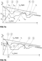
- FIGs 7a and 7b a time course of vehicle speed V F , wheel circumferential speed V R , reference speed V RFE , brake circuit pressure P h for "high wheel”, P L for “low wheel” is shown.
- the slip value ⁇ is the wheel speed at which a wheel becomes unstable and is approximately equal to the reference speed V RFE .
- the typical characteristic values are shown, such as ⁇ limit or (reference speed V RFE ), subpoints 1,1', 2, 4 for pressure reduction P ab (slip value ⁇ exceeded) and times 3 and 5 for pressure build-up P auf (slip value ⁇ fallen below).
- a "select-low" control ( Fig. 7b )
- a pressure is set that is so low that no wheel locks. This means that about 20% of the full braking effect is lost.
- Fig. 7a a "select-high" control.
- the description of the ABS control assumes the general principles known from patent applications, brake manuals and brochures.
- a slip value ⁇ that depends on many factors, the maximum tire circumferential force is exceeded, which then leads to the wheel locking without control.
- the controller which evaluates the wheel acceleration (positive and negative) and the slip ⁇ , then effectively controls the pressure with pressure reduction P down and pressure build-up P up to achieve the desired, optimal braking and cornering force.
- Fig. 7a thus an example of a time sequence of a "select high" control in a brake circuit with two wheel brakes.
- the pressure is further built up.
- a further pressure build-up P on causes that shortly after exceeding the ⁇ limit at pressure level p 2 the wheel V R2 also becomes unstable at time 2 and the wheel circumferential speed V R2 decreases sharply.
- the pressure is reduced via the pressure supply, e.g.
- the pressure is gradually built up.
- the pressure is increased by 70% of the previous ⁇ p ab value, for example, and in a second step by a further 30%, so that the pressure p 2 is reached again and subsequently exceeded.
- the pressure sensor p/U is preferably used to measure the pressure.
- the slip limit is exceeded again.
- the pressure is then reduced again as at time 2 and subsequently increased again in stages so that the wheel falls below the slip limit again at time 5. This control process is continued during control.
- Fig. 7b shows a specific example of a "select-low" control in a brake circuit with two wheel brakes.
- the pressure is reduced by ⁇ p ab and increased again in stages.
- Fig. 7a and 7b show only the general aspects of the "select-low”/"select-high” control. Many extensions are conceivable, such as a new test with a “select-high” control if the pressure level on the "high” wheel is reduced. Alternatively, the "select-low” wheel can leave the blocked state again without control and exceed the ⁇ limit. This possible wheel speed curve is shown in Fig. 7a designated with X. After that, a new "select-low”/"select-high” test can be carried out with a possible switchover from a "select-high” control to a "select-low” control.
- the first control unit 9 switches from a "select-low” control to a "select-high” control if the first control unit 9 detects that the vehicle is on an inhomogeneous surface, e.g. a partially icy road.
- the brake system 2 can set different pressures in the individual brake circuits BK1, BK2 by means of the first pressure supply unit 6.
- the pressures already determined based on the Figures 1b , 8 and 9 outlined designs.
- the control unit 9 monitors the pressures in the individual wheel brakes RB1, RB2, RB3, RB4 that lead to the wheels locking.
- the first control unit 9 switches from a "select-low” control to a "select-high” control in order to achieve a very good braking result even in the case of the error.
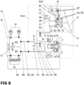
- Fig. 8 shows a schematic diagram of a braking system 2, which comprises a first module (referred to as X-Boost) and a second module.
- the first module - the X-Boost - has a first pressure supply unit 6 with an electric motor drive 8 and a second pressure supply unit 14 with a master brake cylinder 22 and an actuating element 26 with a brake pedal.
- a valve device with various solenoid and check valves is provided.
- the second module and specifically the third pressure supply unit 90 comprises an electrically driven motor-pump unit 91 with a pump with an electric motor drive.
- the third pressure supply unit 90 can be any ESP unit.
- a suitable ESP unit is shown in the DE 10 2014 205 645 A1 described in detail.
- a standard ABS unit without ESP function can be used as a second module.
- the two modules are designed to apply pressure medium to two brake circuits BK1 and BK2, whereby the modules are preferably connected hydraulically in series.
- the X-Boost is attached to the bulkhead of a vehicle, to which the second module (ESP unit) is connected at two hydraulic interfaces or connection points A1, A2 (see thick black dots in the Fig. 8 regarding BK1, BK2) via hydraulic lines.
- the first pressure supply unit 6 is connected to the first brake circuit BK1 or the corresponding interface via a first hydraulic line HL1. Furthermore, a second hydraulic line HL2 is provided for connecting the first pressure supply unit to the second brake circuit or the corresponding interface.
- the second pressure supply unit 14 of the X-Boost has only one master brake cylinder 22 with a piston 24 and a piston chamber.
- the second pressure supply unit 14 is designed as a single circuit and is connected to the brake circuit BK1 or the corresponding hydraulic interface via a third hydraulic line HL3 and a feed valve 69.
- a fluid connection to the second hydraulic line HL2 is via an optional (indicated by a dashed border) first isolating valve BP1.
- the second pressure supply unit 14 can be separated from the brake circuits BK1, BK2 by closing the feed valve 69 in such a way that in normal brake-by-wire operation without errors (e.g. without brake circuit failure) the actuating element 26 only acts on a travel simulator 28.
- the brake circuits BK1 and BK2 can be separated (preferably de-energized-open) via the optional first isolating valve BP1, if present.
- the master brake cylinder 22 of the second pressure supply unit 14 can be connected either only to the first brake circuit BK1 or to the first and second brake circuits BK1, BK2 by opening the first isolating valve BP1.
- the feed valve 69 is designed as a de-energized-open valve. As long as there is still power, it is opened, so that the second pressure supply unit 14 is no longer hydraulically decoupled from the brake circuits BK1, BK2.
- the first pressure supply unit 6 also acts optionally on the second brake circuit BK2 (first isolating valve BP1 closed) or both brake circuits BK1, BK2 (first isolating valve BP1 open or open when de-energized). In normal operation, the first isolating valve BP1 is open, so that the first pressure supply unit 6 supplies both brake circuits BK1, BK2 with pressure and the second pressure supply unit 14 is decoupled from the first brake circuit BK1 by the closed feed valve 69.
- the brake circuit BK1 can be decoupled from the first pressure supply unit 6 using the first isolating valve BP1, so that if there is a leak in the first brake circuit BK1, the second brake circuit BK2 can continue to operate without hydraulic fluid losses.
- the isolating valve BP1 is designed as a solenoid valve, with the ball seat of the isolating valve BP1 being connected via a connection (valve seat connection) to the section of the hydraulic line that leads to the first pressure supply unit 6. This means that the isolating valve BP1 can be safely closed by energization even if the first brake circuit BK1 fails and is not forced open by higher pressures when the first pressure supply unit 6 is in operation.
- the second pressure supply unit 14 feeds the travel simulator 28 via a sniffer hole in a wall of the master brake cylinder 22, so that a progressive haptic resistance in the form of a restoring force can be felt depending on the magnitude of the actuation of the actuating element 26.
- the magnitude of the actuation can be understood here as how "hard and/or how far" a driver actuates the actuating element 26 designed as a brake pedal and thus pushes the piston 24 into the master brake cylinder 22.
- the progressive haptic resistance is also referred to as the pedal characteristic.
- a travel simulator valve 29 may be provided to shut off the connection to the travel simulator 28.
- the second pressure supply unit 14 has at least one sniffer bore 38, which is connected to a reservoir 40 via hydraulic lines.
- the reservoir 40 is also part of the brake system 2.
- a check valve RVHZ and a throttle DR can be arranged in the hydraulic line between the sniffer bore 38 and the reservoir 40. Using this check valve RVHZ and the first pressure supply unit 6, it is possible to carry out a diagnosis of the condition of sealing elements arranged within the first pressure supply unit 6 and within the travel simulator 28. When checking the seal of the master brake cylinder 22, the travel simulator valve 29 - if present - can be closed.
- the master brake cylinder 22 has two sealing elements 42a, 42b, which are designed as ring seals.
- the sniffer bore 38 is arranged between the two sealing elements 42a, 42b.
- a throttle DR is arranged in the connection between the sniffer bore 38, which is arranged between the two sealing elements 42a, 42b, and the reservoir 40.
- the throttle DR is dimensioned in terms of its flow rate so that the pedal characteristics are not significantly changed if the sealing element 42a fails (3 mm pedal travel in 10 s).
- the throttle DR can be used to compensate for the volume of the pressure medium due to temperature.
- a pressure limiting valve ÜV is provided in the design variant according to Fig. 8 connected via a bore to the piston chamber of the first pressure supply unit 6 so that the high pressure peaks are reduced and damage to the system is avoided.
- a suction valve NV is also in fluid communication with the piston chamber of the first pressure supply unit 6 and enables the supply of pressure medium from the reservoir 40.
- the first pressure supply unit 6 can independently introduce additional pressure medium into the brake circuits BK1, BK2.
- An additional sniffer hole in the cylinder of the first pressure supply unit 6 enables volume compensation in the initial position of the piston of the first pressure supply unit 6.
- the third pressure supply unit 90 is in the Fig. 8 only shown schematically. It ultimately supplies four wheel brakes RB1, RB2, RB3 and RB4.
- the wheel brakes RB1, RB2 serve a front axle VA of the vehicle and the wheel brakes RB3 and RB4 serve a rear axle HA of the vehicle.
- the vehicle can be a purely electric vehicle or a hybrid vehicle.
- the first brake circuit BK1 is connected to the wheel brakes RB1 and RB2 and the second brake circuit BK2 to the wheel brakes RB3 and RB4.
- Fig. 8 For the hydraulic arrangement shown, a corresponding assignment is advantageous.
- the third pressure supply unit 90 also has a control unit 95 ("ECU-ESP").
- the second pressure supply unit 14 also has a printed circuit board which has a level sensor NST which detects the position of a magnetic float NS within the reservoir 40.
- the PCB also has sensors 30a, 30b for detecting the pedal travel and a travel difference between the piston 24 and the pedal travel.
- a suction valve 70b is provided in the first brake circuit BK1, which connects the pump of the third pressure supply unit 90 to the reservoir 40.
- the two brake circuits BK1, BK2 are connected to the reservoir 40 via the respective hydraulic lines HL1, HL2 via a suction valve 70b or 70c to the Suction of pressure medium.
- the suction valve 70c preferably has a diameter in the range of 30 mm to 50 mm and especially a diameter of 40 mm.
- the design example optionally has a control of the clearance between the brake pads and the disc brake.
- the wheel brakes RB1, RB2, RB3, RB4 can be designed as frictionless wheel brakes RB1, RB2, RB3, RB4.
- disc brakes with brake pads that are spaced apart with a clearance without pressure in the brake system enable a reduction in frictional resistance. This can be achieved by using rollback seals, brake pad return springs or active retraction of the brake pads by generating a vacuum using pressure supply 6, as in EP 2 225 133 carried out by the applicant.
- the air gap in the wheel brake RB1, RB2, RB3, RB4, which changes during operation, can be measured for each wheel or brake circuit by evaluating the pressure curve.
- a corresponding measurement can be carried out during servicing, but also while the vehicle is in operation. The measurement is preferably carried out when the vehicle is stationary or after braking.
- the clearance is first quickly overcome by means of a piston travel control of the first pressure supply unit 6.
- the use of a brushless motor as an electric motor drive 8 of the first pressure supply unit 6 with a small time constant is preferable, since the clearance can be overcome without the driver noticing this when applying the brake.
- the braking system 2 can be controlled in such a way that the vehicle's electric motor acts in the clearance phase. This means that a braking effect is generated immediately when the brake is applied.
- differences in the clearances of the wheel brakes RB1, RB2, RB3, RB4 are compensated by inlet valves EV1 to EV4 the second module (ESP unit) and/or the electric motor of one or more vehicle axles is used to generate a braking effect at the start of braking.
- the clearance can generally reduce or prevent stick-slip effects of new braking systems at low speeds.
- the brake system 2 implements a stutter brake in a very simple variant in the event of a failure (error case 4) of the ESP unit.
- error case 4 By moving the piston of the first pressure supply unit 6 back and forth between an upper and lower pressure range, locking of the wheels is avoided and steerability is maintained.
- no measured values e.g. pressure and wheel speeds, are required in comparison to a 1-channel ABS operation.
- the automated stutter brake leads to sufficient braking distances (approx. 200% of the braking distance with ABS compared to a full wheel-individual ABS) and acceptable stability by maintaining steerability.
- the braking system according to the invention can provide the decisive advantage that the brake pedal only acts on the piston 24 and is separated from the brake circuits BK1, BK2 via the feed valve 69.
- the function of the automated stutter brake can be controlled by the driver in comparison to the state of the art ( WO2011/098178 ) should not be disturbed.
- a 1-channel ABS operation with "select-low" control (error case 3) can be implemented.
- This form of 1-channel ABS operation requires measured values such as pressure and wheel speeds, which can be read in by the ESP unit via a communicative connection/interface, e.g. CAN interface.
- the electric motor drive 8 of the first pressure supply unit 6 is connected to the control unit 9 (ECU-DV) of the X-Boost via two redundant three-phase lines and the electronics are (partially) redundant.
- the electronics are connected to two redundant power supplies in at least one embodiment. This means that the probability of failure of the electric motor drive 8 can be reduced by a factor of 4-10 and the error case (failure of the first pressure supply unit 6) can be further significantly reduced.
- the control unit 95 of the ESP unit 90 and the control unit 9 (ECU-DV) of the X-Boost are connected to one another via the communicative connection 100, for example a CAN bus.
- the communicative connection 100 for example a CAN bus.
- Fig. 9 shows an alternative design of the X-Boost according to Fig. 8
- a second isolating valve TVBK2 is provided in the second hydraulic line HL2.
- This second isolating valve TVBK2 makes it possible to hydraulically decouple the second brake circuit BK2 from the first pressure supply unit 6.
- the first pressure supply unit 6 can thus selectively provide pressure medium in the first brake circuit BK1 or in the second brake circuit BK2 or in both brake circuits. If volume loss is detected in the second brake circuit BK2, this can be decoupled.
- a third isolating valve BP2 is provided in the first hydraulic line HL1 between the first isolating valve BP1 and the first connection point A1 for the first brake circuit BK1.
- This third isolating valve BP2 is preferably arranged such that the third hydraulic line opens into the first hydraulic line HL1 in a hydraulic connection between the first isolating valve BP1 and the third isolating valve BP2.
- the third isolating valve BP2 makes it possible to hydraulically decouple the first brake circuit BK1 from both the first pressure supply unit 6 and the second pressure supply unit 14.
- the first pressure supply unit 6 fails, to introduce pressure medium from the second pressure supply unit 14 via the feed valve 69, the first isolating valve BP1 and the second isolating valve TV BK2 into the second brake circuit BK2. If the third isolating valve BP2 is closed, no pressure medium is released into the first brake circuit BK1.
- FIG. 10 and 11 is a schematic diagram of the third pressure supply unit (ESP unit) during a pressure reduction (cf. Fig. 11 ) or a pressure build-up (cf. Fig. 11 ) in the first error case with a yaw moment control.
- the control is similar to the 4-channel ABS, which is also possible in the first error case.
- the yaw moment control as a difference to the 4-channel ABS control - both the pressure reduction and the pressure build-up take place via the inlet valves EV1-EV4 and USV valves.
- Open valves relevant to the flow are each marked with an asterisk (*).
- the state of the other solenoid valves is not explicitly stated.
- at least the inlet valves EV2, EV3, EV4 are closed when the pressure is reduced by active current supply.
- the valves are valves that can be controlled by means of a PWM signal, open can also be understood in the sense of this application to mean that these valves are controlled by a PWM signal so that they set a predetermined opening cross-section.
- a flow rate through the respective valve can be controlled.
- the inlet valves EV1-EV4 and the valves USV1, USV2 can be controlled using a PWM signal. This means that in the situations described below, a flow rate can be regulated or controlled by these valves.
- Fig. 10 is shown as an example of a wheel-selective yaw moment control when pressure builds up in the wheel brake RB4.
- the inlet valve EV1 assigned to the respective wheel brake, here the wheel brake RB4, and the isolating valve USV2 assigned to the respective brake circuit, here the first brake circuit BK1 are flowed through with pressure medium.
- the valves do not have to be are actively controlled because they are passively open when de-energized and allow a bidirectional volume flow of the pressure medium.
- the other inlet valves EV1-EV3, through which no pressure is to be built up (RB1-RB3), are controlled in such a way that the solenoid valves are transferred from the open state to the closed state when energized.
- Controlling a valve when de-energized in this sense can be understood to mean that the inlet valves EV1-EV3 are closed, i.e. are not switched to pass pressure medium.
- the HSV valves for the selective pressure generation in the wheel brake RB4 are also closed, i.e. are not switched to pass pressure medium.
- one wheel brake RB1, RB2, RB3, RB4 of a brake circuit is then pressurized.
- a further possible extension of the yaw moment control is through sequential or simultaneous multiplex operation of the circuit isolation valves BP1/BP2 and TV BK2 of the first module (embodiment according to Fig.9 ) is possible. This allows a pressure in a wheel brake RB1, RB2, RB3, RB4 (e.g. RB4 of the right rear wheel) to be brought to a pressure level, whereby when the pressure valve is reached, the circuit isolation valve TV BK2 is closed to maintain the pressure.
- a different pressure level can be set in a wheel brake RB1, RB2, RB3, RB4 of the other brake circuit (e.g. RB2 of the right front wheel), whereby the second brake circuit isolation valve BP1 or alternatively BP2 is closed to maintain the pressure.
- the brake circuit isolation valves BP1/BP2 and TV BK2 are required to maintain the pressure, since the inlet valves of the wheel brakes RB1, RB2, RB3, RB4 have check valves connected in parallel. This enables pressure to be maintained in the second module. (ESP unit) is not possible if the pressure is reduced or if a lower pressure level is set in the second brake circuit.
- wheel brakes RB1, RB2, RB3, RB4 can be controlled individually and wheel-selectively in an analog manner, thus implementing a wheel-selective yaw moment control.
- the yaw moment control can be carried out brake circuit-selectively, so that two wheel brakes of a brake circuit are each controlled together.
Landscapes
- Engineering & Computer Science (AREA)
- Transportation (AREA)
- Mechanical Engineering (AREA)
- Regulating Braking Force (AREA)
- Valves And Accessory Devices For Braking Systems (AREA)
- Braking Systems And Boosters (AREA)
Applications Claiming Priority (4)
| Application Number | Priority Date | Filing Date | Title |
|---|---|---|---|
| DE102020101988 | 2020-01-28 | ||
| DE102020102590.4A DE102020102590B4 (de) | 2020-01-28 | 2020-02-03 | Bremssystem sowie Verfahren zum Steuern eines Bremssystems |
| PCT/EP2021/051788 WO2021151910A1 (fr) | 2020-01-28 | 2021-01-27 | Système de freinage et procédé de commande d'un système de freinage |
| EP21702236.7A EP4096977B1 (fr) | 2020-01-28 | 2021-01-27 | Système de freinage et procédé de commande d'un système de freinage |
Related Parent Applications (2)
| Application Number | Title | Priority Date | Filing Date |
|---|---|---|---|
| EP21702236.7A Division EP4096977B1 (fr) | 2020-01-28 | 2021-01-27 | Système de freinage et procédé de commande d'un système de freinage |
| EP21702236.7A Division-Into EP4096977B1 (fr) | 2020-01-28 | 2021-01-27 | Système de freinage et procédé de commande d'un système de freinage |
Publications (2)
| Publication Number | Publication Date |
|---|---|
| EP4516605A2 true EP4516605A2 (fr) | 2025-03-05 |
| EP4516605A3 EP4516605A3 (fr) | 2025-05-14 |
Family
ID=76753620
Family Applications (2)
| Application Number | Title | Priority Date | Filing Date |
|---|---|---|---|
| EP21702236.7A Active EP4096977B1 (fr) | 2020-01-28 | 2021-01-27 | Système de freinage et procédé de commande d'un système de freinage |
| EP25150506.1A Pending EP4516605A3 (fr) | 2020-01-28 | 2021-01-27 | Système de freinage et procédé de commande d'un système de freinage |
Family Applications Before (1)
| Application Number | Title | Priority Date | Filing Date |
|---|---|---|---|
| EP21702236.7A Active EP4096977B1 (fr) | 2020-01-28 | 2021-01-27 | Système de freinage et procédé de commande d'un système de freinage |
Country Status (6)
| Country | Link |
|---|---|
| US (3) | US20230053950A1 (fr) |
| EP (2) | EP4096977B1 (fr) |
| JP (3) | JP2023511970A (fr) |
| CN (3) | CN120773710A (fr) |
| DE (1) | DE102020102590B4 (fr) |
| WO (1) | WO2021151910A1 (fr) |
Families Citing this family (12)
| Publication number | Priority date | Publication date | Assignee | Title |
|---|---|---|---|---|
| JP7491001B2 (ja) * | 2020-03-19 | 2024-05-28 | 株式会社アドヴィックス | 車両用制動装置 |
| DE102021119715A1 (de) | 2021-07-29 | 2023-02-02 | Zf Active Safety Gmbh | Verfahren zum Betreiben einer Bremsanlage, Computerprogrammprodukt und Steuergerät |
| DE102021210697A1 (de) * | 2021-09-24 | 2023-03-30 | Zf Cv Systems Europe Bv | Verfahren zum Betreiben eines Bremssystems eines Nutzfahrzeuges |
| CN114087302B (zh) * | 2021-10-19 | 2024-02-27 | 中国科学院电工研究所 | 一种电子机械制动线控系统构型控制方法及控制系统 |
| KR20230065816A (ko) * | 2021-11-05 | 2023-05-12 | 현대모비스 주식회사 | 차량용 제동장치 |
| US12503092B2 (en) * | 2021-12-02 | 2025-12-23 | Bwi (Shanghai) Co., Ltd. | Electronic stability control-based brake actuation with redundancy |
| DE102022205222A1 (de) | 2022-05-25 | 2023-11-30 | Continental Automotive Technologies GmbH | Modul für ein Bremssystem eines Kraftfahrzeugs und Bremssystem |
| DE102022117667A1 (de) * | 2022-07-14 | 2024-01-25 | Knorr-Bremse Systeme für Nutzfahrzeuge GmbH | Verfahren zum Bestimmen eines Bremsdrucks und druckmittelbetätigte Bremseinrichtung |
| DE102022210243A1 (de) * | 2022-09-28 | 2024-03-28 | Robert Bosch Gesellschaft mit beschränkter Haftung | Verfahren zur Steuerung eines hydraulischen Volumens |
| DE102022210815A1 (de) | 2022-10-13 | 2024-04-18 | Continental Automotive Technologies GmbH | Hydraulische Bremsanlage und Steuerungsverfahren |
| US12570254B2 (en) * | 2023-09-14 | 2026-03-10 | Robert Bosch Gmbh | Decoupled power brake and electronic stability control system in a vehicle |
| CN119305525B (zh) * | 2024-09-23 | 2025-09-16 | 东风越野车有限公司 | 一种大流量esc系统 |
Citations (9)
| Publication number | Priority date | Publication date | Assignee | Title |
|---|---|---|---|---|
| WO2009065709A1 (fr) | 2007-11-21 | 2009-05-28 | Continental Teves Ag & Co. Ohg | Unité de commande de frein |
| DE102009033499A1 (de) | 2008-07-18 | 2010-01-21 | Continental Teves Ag & Co. Ohg | Bremsanlage für Kraftfahrzeuge |
| WO2010088920A1 (fr) | 2009-02-03 | 2010-08-12 | Ipgate Ag | Système de freinage sans simulateur de course |
| EP2225133A2 (fr) | 2007-12-21 | 2010-09-08 | Ipgate Ag | Système de freinage à jeu de garniture de frein adaptable |
| WO2011098178A1 (fr) | 2010-02-15 | 2011-08-18 | Robert Bosch Gmbh | Servofrein ainsi que procédé et dispositif de fonctionnement correspondants |
| WO2012019802A1 (fr) | 2010-07-27 | 2012-02-16 | Robert Bosch Gmbh | Dispositif de couplage pour relier un élément de commande de freinage à un maître-cylindre de frein et procédé de fonctionnement d'un tel dispositif de couplage |
| EP2744691A1 (fr) | 2011-08-15 | 2014-06-25 | Continental Teves AG&Co. Ohg | Unité d'actionnement de frein |
| DE102014205645A1 (de) | 2013-04-24 | 2014-10-30 | Robert Bosch Gmbh | Verfahren zum Betreiben eines Bremssystems für ein Fahrzeug und Steuervorrichtung für ein Bremssystem eines Fahrzeugs |
| DE102016105232A1 (de) | 2016-03-21 | 2017-09-21 | Ipgate Ag | Betätigungsvorrichtung für ein hydraulisches Betätigungssystem, insbesondere eine Kraftfahrzeugbremse oder einen elektrifizierten Kupplungs- und Gangsteller |
Family Cites Families (17)
| Publication number | Priority date | Publication date | Assignee | Title |
|---|---|---|---|---|
| JP2002120715A (ja) * | 2000-10-12 | 2002-04-23 | Toyota Motor Corp | ブレーキ装置 |
| DE102012210809A1 (de) * | 2011-07-27 | 2013-01-31 | Continental Teves Ag & Co. Ohg | Bremsanlage für Kraftfahrzeuge sowie Verfahren zum Betrieb einer Bremsanlage |
| DE102013227066A1 (de) * | 2013-12-23 | 2015-06-25 | Robert Bosch Gmbh | Hydraulisches Bremssystem und Verfahren zum Betreiben eines hydraulischen Bremssystems |
| DE102014212537A1 (de) * | 2014-06-30 | 2015-12-31 | Continental Teves Ag & Co. Ohg | Bremsanlage für ein Kraftfahrzeug |
| DE102016201047A1 (de) * | 2015-01-29 | 2016-08-04 | Continental Teves Ag & Co. Ohg | Bremsanlage für Kraftfahrzeuge |
| DE102016208966A1 (de) * | 2016-05-24 | 2017-11-30 | Robert Bosch Gmbh | Elektronisch druckregelbare Fahrzeugbremsanlage und Verfahren zur Steuerung einer elektronisch druckregelbaren Fahrzeugbremsanlage |
| DE102016211982A1 (de) * | 2016-06-30 | 2018-01-04 | Robert Bosch Gmbh | Bremsvorrichtung für ein Fahrzeug |
| JP6531739B2 (ja) * | 2016-08-09 | 2019-06-19 | トヨタ自動車株式会社 | ブレーキ制御装置 |
| DE102017200955A1 (de) * | 2017-01-20 | 2018-07-26 | Continental Teves Ag & Co. Ohg | Bremssystem für Kraftfahrzeuge |
| DE102017003654A1 (de) * | 2017-04-13 | 2018-10-18 | Lucas Automotive Gmbh | Hydraulische Kraftfahrzeug-Bremsanlage und Steuergerätesystem hierfür |
| DE102017113563A1 (de) * | 2017-06-20 | 2018-12-20 | Ipgate Ag | Bremssystem |
| DE102017213858A1 (de) * | 2017-08-09 | 2019-02-14 | Continental Teves Ag & Co. Ohg | Bremsanlage für Kraftfahrzeuge |
| DE102018206079A1 (de) * | 2018-04-20 | 2019-10-24 | Robert Bosch Gmbh | Mehrkreisiges hydraulisch offenes Bremssystem, insbesondere für ein hochautomatisiertes oder autonomes Fahrzeug |
| DE102018206082A1 (de) * | 2018-04-20 | 2019-10-24 | Robert Bosch Gmbh | Mehrkreisiges hydraulisch offenes Bremssystem, insbesondere für ein hochautomatisiertes oder autonomes Fahrzeug |
| WO2019215030A1 (fr) * | 2018-05-09 | 2019-11-14 | Ipgate Ag | Système de freinage |
| DE102018010168A1 (de) * | 2018-12-28 | 2020-07-02 | Zf Active Safety Gmbh | Hydraulische Kraftfahrzeug-Bremsanlage und Verfahren zum Betreiben derselben |
| DE102019207088A1 (de) * | 2019-05-16 | 2020-11-19 | Continental Teves Ag & Co. Ohg | Bremsanlage für Kraftfahrzeuge sowie Verfahren zu deren Betrieb |
-
2020
- 2020-02-03 DE DE102020102590.4A patent/DE102020102590B4/de active Active
-
2021
- 2021-01-27 CN CN202510981685.0A patent/CN120773710A/zh active Pending
- 2021-01-27 US US17/795,790 patent/US20230053950A1/en active Pending
- 2021-01-27 EP EP21702236.7A patent/EP4096977B1/fr active Active
- 2021-01-27 WO PCT/EP2021/051788 patent/WO2021151910A1/fr not_active Ceased
- 2021-01-27 CN CN202180015385.7A patent/CN115151460A/zh active Pending
- 2021-01-27 JP JP2022545056A patent/JP2023511970A/ja active Pending
- 2021-01-27 CN CN202511673720.9A patent/CN121734335A/zh active Pending
- 2021-01-27 EP EP25150506.1A patent/EP4516605A3/fr active Pending
-
2025
- 2025-02-20 US US19/058,798 patent/US20250196836A1/en active Pending
- 2025-04-17 US US19/182,127 patent/US20250242790A1/en active Pending
- 2025-06-27 JP JP2025109731A patent/JP2025148376A/ja active Pending
- 2025-06-27 JP JP2025109730A patent/JP2025143342A/ja active Pending
Patent Citations (9)
| Publication number | Priority date | Publication date | Assignee | Title |
|---|---|---|---|---|
| WO2009065709A1 (fr) | 2007-11-21 | 2009-05-28 | Continental Teves Ag & Co. Ohg | Unité de commande de frein |
| EP2225133A2 (fr) | 2007-12-21 | 2010-09-08 | Ipgate Ag | Système de freinage à jeu de garniture de frein adaptable |
| DE102009033499A1 (de) | 2008-07-18 | 2010-01-21 | Continental Teves Ag & Co. Ohg | Bremsanlage für Kraftfahrzeuge |
| WO2010088920A1 (fr) | 2009-02-03 | 2010-08-12 | Ipgate Ag | Système de freinage sans simulateur de course |
| WO2011098178A1 (fr) | 2010-02-15 | 2011-08-18 | Robert Bosch Gmbh | Servofrein ainsi que procédé et dispositif de fonctionnement correspondants |
| WO2012019802A1 (fr) | 2010-07-27 | 2012-02-16 | Robert Bosch Gmbh | Dispositif de couplage pour relier un élément de commande de freinage à un maître-cylindre de frein et procédé de fonctionnement d'un tel dispositif de couplage |
| EP2744691A1 (fr) | 2011-08-15 | 2014-06-25 | Continental Teves AG&Co. Ohg | Unité d'actionnement de frein |
| DE102014205645A1 (de) | 2013-04-24 | 2014-10-30 | Robert Bosch Gmbh | Verfahren zum Betreiben eines Bremssystems für ein Fahrzeug und Steuervorrichtung für ein Bremssystem eines Fahrzeugs |
| DE102016105232A1 (de) | 2016-03-21 | 2017-09-21 | Ipgate Ag | Betätigungsvorrichtung für ein hydraulisches Betätigungssystem, insbesondere eine Kraftfahrzeugbremse oder einen elektrifizierten Kupplungs- und Gangsteller |
Also Published As
| Publication number | Publication date |
|---|---|
| EP4516605A3 (fr) | 2025-05-14 |
| US20250196836A1 (en) | 2025-06-19 |
| JP2025148376A (ja) | 2025-10-07 |
| EP4096977B1 (fr) | 2026-04-01 |
| CN121734335A (zh) | 2026-03-27 |
| DE102020102590B4 (de) | 2025-01-09 |
| CN120773710A (zh) | 2025-10-14 |
| WO2021151910A1 (fr) | 2021-08-05 |
| US20250242790A1 (en) | 2025-07-31 |
| JP2023511970A (ja) | 2023-03-23 |
| DE102020102590A1 (de) | 2021-07-29 |
| US20230053950A1 (en) | 2023-02-23 |
| CN115151460A (zh) | 2022-10-04 |
| JP2025143342A (ja) | 2025-10-01 |
| EP4096977A1 (fr) | 2022-12-07 |
Similar Documents
| Publication | Publication Date | Title |
|---|---|---|
| DE102020102590B4 (de) | Bremssystem sowie Verfahren zum Steuern eines Bremssystems | |
| EP3898357B1 (fr) | Système de freinage redondante avec deux alimentations de pression pour véhicule électrique et véhicule autonome de niveau 3 (had) à 5 (ad) | |
| EP3924227B1 (fr) | Système hydraulique muni d'au moins deux circuits hydrauliques et d'au moins deux dispositifs d'alimentation en pression | |
| EP4219255B1 (fr) | Système de freinage redondant avec une alimentation en pression pour les véhicules électriques et les véhicules à conduite autonome de niveau 3 (had) à niveau 4 (fad) | |
| EP3962792B1 (fr) | Système de freinage et procédé de commande d'un système de freinage | |
| EP4620753A2 (fr) | Système de dynamique de conduite, véhicule électrique à commande centrale | |
| DE202018006953U1 (de) | Zwei-Box-Bremssystem | |
| EP4169781A1 (fr) | Essieu de véhicule avec moteurs d'entraînement électriques et frein électrohydraulique et autres modules tels que boîte de vitesses, torque vectoring et frein de stationnement | |
| DE102018133218A1 (de) | Redundantes Bremssystem mit einer Druckversorgung für E-Fahrzeuge und Fahrzeuge mit autonomem Fahren der Stufe 3 (HAD) bis Stufe 4 (FAD) | |
| EP2379376A2 (fr) | Procédé de commande de l'actionnement de freins dans un système de freinage hydraulique d'un véhicule et servofrein électromécanique | |
| EP3924229A1 (fr) | Système de freinage présentant un dispositif d'alimentation sous pression et une grille de sécurité pour circuits de freinage | |
| WO2021160296A1 (fr) | Système de freinage | |
| DE102023205413A1 (de) | Druckabbau über Hydraulikventil | |
| DE102023208492A1 (de) | Fadingkompensation | |
| DE102022207137A1 (de) | Bremssystem für Kraftfahrzeuge | |
| WO2024104534A1 (fr) | Maintien de pression dans des systèmes de freinage redondants | |
| DE102019211317A1 (de) | Mehrkreisiges Bremssystem für ein Fahrzeug |
Legal Events
| Date | Code | Title | Description |
|---|---|---|---|
| PUAI | Public reference made under article 153(3) epc to a published international application that has entered the european phase |
Free format text: ORIGINAL CODE: 0009012 |
|
| STAA | Information on the status of an ep patent application or granted ep patent |
Free format text: STATUS: THE APPLICATION HAS BEEN PUBLISHED |
|
| AC | Divisional application: reference to earlier application |
Ref document number: 4096977 Country of ref document: EP Kind code of ref document: P |
|
| AK | Designated contracting states |
Kind code of ref document: A2 Designated state(s): AL AT BE BG CH CY CZ DE DK EE ES FI FR GB GR HR HU IE IS IT LI LT LU LV MC MK MT NL NO PL PT RO RS SE SI SK SM TR |
|
| REG | Reference to a national code |
Ref country code: DE Ref legal event code: R079 Free format text: PREVIOUS MAIN CLASS: B60T0013740000 Ipc: B60T0017220000 |
|
| PUAL | Search report despatched |
Free format text: ORIGINAL CODE: 0009013 |
|
| AK | Designated contracting states |
Kind code of ref document: A3 Designated state(s): AL AT BE BG CH CY CZ DE DK EE ES FI FR GB GR HR HU IE IS IT LI LT LU LV MC MK MT NL NO PL PT RO RS SE SI SK SM TR |
|
| RIC1 | Information provided on ipc code assigned before grant |
Ipc: B60T 8/1755 20060101ALI20250408BHEP Ipc: B60T 13/74 20060101ALI20250408BHEP Ipc: B60T 17/22 20060101AFI20250408BHEP |
|
| STAA | Information on the status of an ep patent application or granted ep patent |
Free format text: STATUS: REQUEST FOR EXAMINATION WAS MADE |
|
| 17P | Request for examination filed |
Effective date: 20251113 |