EP4516618A1 - Dispositif d'accès avec unité de mise hors service - Google Patents
Dispositif d'accès avec unité de mise hors service Download PDFInfo
- Publication number
- EP4516618A1 EP4516618A1 EP24191747.5A EP24191747A EP4516618A1 EP 4516618 A1 EP4516618 A1 EP 4516618A1 EP 24191747 A EP24191747 A EP 24191747A EP 4516618 A1 EP4516618 A1 EP 4516618A1
- Authority
- EP
- European Patent Office
- Prior art keywords
- lever
- locking
- bolt
- locking pawl
- step plate
- Prior art date
- Legal status (The legal status is an assumption and is not a legal conclusion. Google has not performed a legal analysis and makes no representation as to the accuracy of the status listed.)
- Pending
Links
Images


Classifications
-
- B—PERFORMING OPERATIONS; TRANSPORTING
- B61—RAILWAYS
- B61K—AUXILIARY EQUIPMENT SPECIALLY ADAPTED FOR RAILWAYS, NOT OTHERWISE PROVIDED FOR
- B61K13/00—Other auxiliaries or accessories for railways
- B61K13/04—Passenger-warning devices attached to vehicles; Safety devices for preventing accidents to passengers when entering or leaving vehicles
-
- B—PERFORMING OPERATIONS; TRANSPORTING
- B60—VEHICLES IN GENERAL
- B60R—VEHICLES, VEHICLE FITTINGS, OR VEHICLE PARTS, NOT OTHERWISE PROVIDED FOR
- B60R3/00—Arrangements of steps or ladders facilitating access to or on the vehicle, e.g. running-boards
- B60R3/02—Retractable steps or ladders, e.g. movable under shock
-
- B—PERFORMING OPERATIONS; TRANSPORTING
- B61—RAILWAYS
- B61D—BODY DETAILS OR KINDS OF RAILWAY VEHICLES
- B61D23/00—Construction of steps for railway vehicles
- B61D23/02—Folding steps for railway vehicles, e.g. hand or mechanically actuated
-
- E—FIXED CONSTRUCTIONS
- E05—LOCKS; KEYS; WINDOW OR DOOR FITTINGS; SAFES
- E05B—LOCKS; ACCESSORIES THEREFOR; HANDCUFFS
- E05B85/00—Details of vehicle locks not provided for in groups E05B77/00 - E05B83/00
- E05B85/20—Bolts or detents
- E05B85/24—Bolts rotating about an axis
- E05B85/26—Cooperation between bolts and detents
Definitions
- the present invention relates to a boarding device for a vehicle, in particular for a rail vehicle, comprising a linearly displaceable tread plate arrangement with a tread plate and an extension unit operatively connected to the tread plate, in which the tread plate can be displaced along a displacement axis while executing a displacement movement from a retracted position to an extended position and vice versa.
- boarding facilities of the type described above or of a similar design are used.
- a "vehicle” can be understood to mean a wheeled or rail-bound vehicle.
- wheeled vehicles can be transport vehicles for passenger transport, for example buses.
- rail-bound vehicles can also be transport vehicles for passenger transport, for example trams, suburban trains, trains (regional trains, long-distance trains), subways, trams, etc.
- boarding facilities can be used for vehicles of any type in which a height difference or a gap between a platform and a step in the interior of the vehicle must be overcome when people get in or out. Such a situation can also occur, for example, when an aircraft is stopped at a gate or the gate's platform, which is why boarding facilities can also be used for aircraft.
- access devices serve to facilitate entry and exit into a vehicle of the type described above.
- Sliding step devices and folding step devices are well known from the state of the art.
- Sliding step devices are based on the fact that a step plate is moved back and forth between a retracted and an extended position, in particular along a line extending in the transverse direction of the vehicle. Sliding axis. In the extended position, the step plate provides a step surface over which a person can enter or exit the vehicle. In order to ensure such a linear displacement of the step plate, the step plate can be guided in a linearly displaceable manner by means of a guide in a vehicle-side housing or a frame. Sliding steps make it easier to get in and out of a vehicle by bridging a gap between the vehicle and a stopping platform (e.g. a platform edge). Folding steps (in particular ramp-like folding steps) are intended in particular to overcome height differences between the interior of a vehicle (e.g. a floor provided there) and a stopping platform, but can also be used to bridge a gap between the vehicle and the stopping platform.
- a stopping platform e.g. a platform edge
- Sliding step devices are locked in the closed position by default using a device and/or a safety position switch so that they are safely stowed away during travel. This locking must be released if the vehicle is taken out of service. It must also be possible to manually move the step plate or sliding step into the step plate assembly and secure it there. The step plate often locks automatically in the retracted position. Finally, it is necessary to bridge the locking control signal of the sliding step using an external switch.
- the decommissioning concepts known to date can only absorb a very limited amount of force and require that the system is already in a closed position.
- the system is often not closed sufficiently tightly. This is particularly problematic for express trains, as a high level of tightness of the system is extremely important due to the high pressure fluctuations, especially in tunnels.
- the step plate closes a flap on the sliding step device, which seals against the door or door leaf from the outside. When driving The sealing flap is held in a closed, sealed position by the locked step plate. Loads on the sealing flap caused by pressure fluctuations or aerodynamic loads are thus transferred to the step plate and the locking mechanism of the boarding aid.
- the present invention is based on the object of providing an access device with which a simple and safe manual transfer of the step plate arrangement into a decommissioning position is possible.
- the access device should close securely in the decommissioning unit and seal the vehicle sufficiently.
- the decommissioning unit therefore consists of a permanently mounted unit which has the crescent-shaped, rotating lever.
- the locking bolt is located on the step plate or on the movable part of the extension and can be pulled in the direction of the vehicle by rotating the lever that contacts the locking bolt.
- the lever is arranged in such a way that it can then reach behind the locking bolt when the lever is rotated and, due to the positioning of the lever's axis of rotation relative to the locking bolt and the curvature of the lever, can pull it in the direction of the vehicle when the locking bolt is retracted sufficiently far into the step plate arrangement.
- the end axis of rotation of the lever is arranged to the side of the sliding axis in relation to the sliding axis or sliding direction of the locking bolt.
- the crescent-shaped lever it is also possible for the crescent-shaped lever not to have a uniform curvature, but rather for this to vary in its course. changes, for example increases. It is important that turning the lever causes the locking bolt to be pulled in.
- the special contour of the lever means that increased resistance, e.g. caused by seals, can be overcome with little effort.
- a decommissioning switch is activated, which signals that the step plate is in the correct position in the boarding device or, if applicable, in a housing of the boarding device.
- the step plate In the non-operating position, the step plate is positively secured by the lever against displacement in the extension direction of the sliding step.
- the decommissioning system can absorb all aerodynamic operating loads that are transmitted through the sealing flap when closed. Due to the high load capacity of the decommissioning system, it can be integrated into the vehicle's safety loop.
- the step plate By turning the sickle-shaped lever, the step plate can be pulled into the non-operating position.
- the lever can be turned manually via a contact area that is accessible from the outside.
- This contact area can be formed, for example, by an upright axis of rotation of the lever that can be contacted from above, i.e. in the area of the vehicle floor.
- a design that allows a tool to be attached is possible, such as a screwdriver, an Allen key or a similar tool.
- the contact area can be designed in such a way that the axis of rotation and thus the lever can be turned by hand, for example using a rotary wheel.
- a spring element in the area of the axis of rotation, which either supports turning the lever towards the non-operating position or turning the lever back to the starting position.
- the spring element also serves to create a locking position in the open or closed position.
- An advantageously provided locking pawl ensures that turning the lever into the non-operating position is not possible if the lever has not engaged behind the locking bolt. This is the case if the treadle is extended too far and the lever is turned past the locking bolt before it does.
- the pawl is mounted so that it can rotate and can assume a basic position and a locking position. In the basic position, the lever can reach behind the locking bolt of the treadle and pull it towards it. In the locking position, the pawl prevents the lever from turning. A spring element causes the pawl to move into the locking position if it is not blocked.
- the locking bolt on the step plate blocks the pawl depending on its position. If the step plate is moved towards the vehicle, the locking bolt contacts the pawl on one side and turns it into its basic position and then holds it in this position. As already explained, it is only in this position that the lever can reach behind the locking bolt and pull the step plate towards it.
- the locking bolt is disengaged from the pawl.
- the pawl is held in position by a bolt on the crescent-shaped lever. If the lever is turned in this situation, it comes into contact with the pawl, preventing it from turning further into the out-of-service position. This in turn also prevents the out-of-service switch from detecting and transmitting the correct position of the retracted treadle. This missing signal can therefore prevent the vehicle from driving with the treadle out of service.
- the lever has a lever bolt at its free end, which corresponds to the pawl in such a way that the pawl blocks the rotational movement of the lever in the direction of the inoperative position by contact with the lever bolt.
- the pawl can preferably have a recess for receiving the lever bolt, which is designed and arranged such that the lever is received in the recess and blocked in its rotational movement in the direction of the inoperative position when the locking bolt arranged on the treadle is out of engagement with the pawl and the pawl is in its locking position.
- the locking pawl is arranged and aligned in its basic position such that the recess is open in the insertion direction and its main extension axis is aligned essentially along the displacement axis of the tread plate.
- the locking bolt arranged on the tread plate is arranged laterally offset in the horizontal plane to the locking pawl on the tread plate so that it can be moved past the locking pawl and the recess in the displacement direction. If the tread plate is pushed in sufficiently far, the locking bolt is in its second and third position to the side of the side surface of the locking pawl, which prevents the locking pawl from moving into the locking position.
- the recess In its locked position, the recess is located on a path of movement of the lever bolt and is opened against the direction of movement of the lever bolt into its inoperative position so that the lever bolt can be moved into the recess.
- the lever can preferably have a retaining recess in its rear area facing its axis of rotation, in which the lever bolt is in the non-operating position and is thus positively locked in the direction of movement of the tread plate.
- the lever bolt can only assume this position if the movement is not blocked by the locking pawl.
- the locking bolt is attached to the tread plate also includes an indirect attachment to the tread plate, for example to additional elements of the tread plate.
- the extension unit is guided in a linearly displaceable manner via a suitable guide, for example a roller or rail guide, in a guide device provided on the vehicle.
- the tread plate can also be guided or arranged in a linearly displaceable manner, for example on the underside, via a guide, for example a roller or rail guide, in a guide device provided on the vehicle.
- the drive unit mentioned is preferably connected directly to the tread plate or a component attached to it, for example a tread plate carrier. Due to the operative connection provided between the tread plate and the extension unit, the extension unit can be moved along the displacement axis when the tread plate is linearly displaced, i.e. the drive unit can cause a linear displacement of the tread plate and the extension unit along the displacement axis, i.e.
- a mechanical transmission means e.g. a rod or a drive belt
- the drive unit can in particular be an electric motor drive. The displacement of the tread plate and the extension unit when the displacement movement of the tread plate arrangement is carried out takes place in the same direction and simultaneously. The extension unit and tread plate are also moved at the same speed.
- FIG. 1 A first embodiment of an access device according to the invention is shown in a perspective view.
- the access device is used as an entry and exit aid in a vehicle (not shown), or is integrated into the vehicle.
- the vehicle is a rail vehicle.
- access devices are in the Usually arranged on the side of the vehicle to allow people to board from a platform located on the side of the vehicle.
- the boarding device comprises a linearly displaceable step plate arrangement 20, which is composed of a step plate 22 and an extension unit 24 operatively connected to the step plate 22.
- a step plate 22 When a person gets in or out, the step plate 22 is subjected to a step load, ie the person's weight is applied to it.
- the step plate 22 Via a drive unit 26, the step plate 22 can be displaced along a displacement axis V by executing a displacement movement from a retracted position to an extended position and vice versa.
- the tread plate 22 is positioned in the extended position.
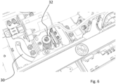
- Figure 2 illustrates the structure of the boarding device according to the invention with a decommissioning unit 28 fixed to the vehicle with a sickle-shaped rotatable lever 30 which can be moved from an operating position (cf. Fig. 1 ) into an out-of-service position (cf. Fig. 8 ) and back.
- the rotary movement is driven manually via a contact area 32 which is accessible from the outside and is arranged in the area of a rotation axis of the lever 30.
- the contact area 32 has a receptacle for a square key.
- the contact area 32 or the axis of rotation of the lever 30 is provided with a spring element 34, which applies a spring force to the lever 30 that acts in the direction of the operating position of the lever 30.
- the spring element 34 causes a detent.
- a locking pawl 36 can be seen, which is also rotatable and spring-loaded and is attached to a stationary support 38 of the boarding device.
- the locking pawl 36 is from a basic position (cf. Fig. 2 ) into a locking position (cf. Fig, 6 ) swiveling.
- a locking bolt 40 is provided on the tread plate 22, which can be moved with the tread plate 22 along the displacement axis V.
- Fig. 3 shows a perspective enlarged view of the decommissioning unit 28 arranged in a fixed position on the vehicle.
- a decommissioning switch 42 can be seen, which is actuated when a lever bolt 44 arranged at the free end of the lever 30 is in the decommissioning position.
- the decommissioning switch 42 can generate and transmit a signal that signals a proper decommissioning position to the train control.
- the treadle assembly 20 is shown in the position in which the pawl 36 is in its basic position.
- Figure 4 shows the situation from above, Figure 5 from below.
- the locking bolt 40 contacts a side surface 46 of the pawl 36 and thereby holds it in its basic position.
- the locking bolt 40 can be moved along the side surface 46.
- the tread plate 22 is located far enough in the tread plate arrangement so that the lever 30 can engage behind the locking bolt 40 (cf. Figure 5 ).
- the locking bolt 40 is pulled in the direction of the vehicle, i.e. into the step plate arrangement 20.
- FIGS. 6 and 7 show the situation in which the tread plate arrangement is in the non-operational position. It can be seen that the locking bolt 40 is located in a retaining recess 48 of the lever 30. The retaining recess 48 holds the locking bolt 40 and blocks it in a form-fitting manner against extension along the displacement axis V.
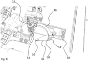
- Fig 8 shows the locking pawl 36 in the locking position from above. It can be seen that this is positioned laterally pivoted out over the support 38.
- the lever bolt 44 is located in a recess 50 of the locking pawl 36 and is thus secured against further rotation in the direction of the decommissioning position. This prevents the decommissioning switch 42 from detecting a correct position of the retaining bolt even though the step plate 22 is not properly retracted.
- the figures further illustrate that the design and arrangement of the lever 30 and the locking bolt 40 are selected such that Rotational movement of the lever 30 causes the locking bolt 40 to be pulled along the displacement axis V.
Landscapes
- Engineering & Computer Science (AREA)
- Mechanical Engineering (AREA)
- Vehicle Step Arrangements And Article Storage (AREA)
- Lock And Its Accessories (AREA)
Applications Claiming Priority (1)
| Application Number | Priority Date | Filing Date | Title |
|---|---|---|---|
| DE202023104989.3U DE202023104989U1 (de) | 2023-08-31 | 2023-08-31 | Zustiegeinrichtung mit Ausserbetriebnahmeeinheit |
Publications (1)
| Publication Number | Publication Date |
|---|---|
| EP4516618A1 true EP4516618A1 (fr) | 2025-03-05 |
Family
ID=92208739
Family Applications (1)
| Application Number | Title | Priority Date | Filing Date |
|---|---|---|---|
| EP24191747.5A Pending EP4516618A1 (fr) | 2023-08-31 | 2024-07-30 | Dispositif d'accès avec unité de mise hors service |
Country Status (3)
| Country | Link |
|---|---|
| US (1) | US20250074315A1 (fr) |
| EP (1) | EP4516618A1 (fr) |
| DE (1) | DE202023104989U1 (fr) |
Citations (4)
| Publication number | Priority date | Publication date | Assignee | Title |
|---|---|---|---|---|
| FR2226298A1 (fr) * | 1973-04-18 | 1974-11-15 | Linke Hofmann Busch | |
| FR2738197A1 (fr) * | 1995-09-01 | 1997-03-07 | Productions Sa B V | Marchepied escamotable pour vehicule roulant |
| JP2016159755A (ja) * | 2015-03-02 | 2016-09-05 | 株式会社京三製作所 | 転落防止装置 |
| EP3434547A1 (fr) * | 2016-03-24 | 2019-01-30 | Kyosan Electric Mfg. Co., Ltd. | Dispositif antichute |
-
2023
- 2023-08-31 DE DE202023104989.3U patent/DE202023104989U1/de active Active
-
2024
- 2024-07-30 EP EP24191747.5A patent/EP4516618A1/fr active Pending
- 2024-08-29 US US18/819,717 patent/US20250074315A1/en active Pending
Patent Citations (4)
| Publication number | Priority date | Publication date | Assignee | Title |
|---|---|---|---|---|
| FR2226298A1 (fr) * | 1973-04-18 | 1974-11-15 | Linke Hofmann Busch | |
| FR2738197A1 (fr) * | 1995-09-01 | 1997-03-07 | Productions Sa B V | Marchepied escamotable pour vehicule roulant |
| JP2016159755A (ja) * | 2015-03-02 | 2016-09-05 | 株式会社京三製作所 | 転落防止装置 |
| EP3434547A1 (fr) * | 2016-03-24 | 2019-01-30 | Kyosan Electric Mfg. Co., Ltd. | Dispositif antichute |
Also Published As
| Publication number | Publication date |
|---|---|
| DE202023104989U1 (de) | 2024-12-03 |
| US20250074315A1 (en) | 2025-03-06 |
Similar Documents
| Publication | Publication Date | Title |
|---|---|---|
| EP1853474B1 (fr) | Porte coulissante pivotante | |
| EP3899180B1 (fr) | Dispositif de positionnement pour element de porte d'un véhicule automobile | |
| AT500017B1 (de) | Schwenkschiebetür für fahrzeuge | |
| EP3942138B1 (fr) | Dispositif d'ouverture pour un élément de porte de véhicule à moteur | |
| AT500462B1 (de) | Schiebetür bzw. schwenkschiebetür | |
| EP3589524B1 (fr) | Ensemble marchepied coulissante pour véhicule automobile ou pour véhicule ferroviaire | |
| EP3899179B1 (fr) | Dispositif d'installation pour une porte de véhicule automobile | |
| EP3795787B1 (fr) | Dispositif de porte de véhicule à double battant pourvu de pré-verrouillage d'un battant de porte placé avant | |
| CH621976A5 (fr) | ||
| DE4327084C2 (de) | Vorrichtung für das automatische Öffnen und Schließen einer Gleittür | |
| DE102019112398A1 (de) | Aufstellvorrichtung für ein Kraftfahrzeugtürelement | |
| EP3684667B1 (fr) | Véhicule ferroviaire comprenant un élément de sol mobile au niveau de l'ouverture de la porte | |
| EP3974281B1 (fr) | Dispositif de montée pour un véhicule | |
| EP3812234B1 (fr) | Passerelle pour un véhicule de transport de personnes et véhicule de transport de personnes | |
| EP4516618A1 (fr) | Dispositif d'accès avec unité de mise hors service | |
| EP1892134A1 (fr) | Dispositif anti-soleil avec pare-soleil électrique | |
| EP1857085A2 (fr) | Rampe d'accès démontable pour véhicules de transport en commun régionaux et longue distance | |
| EP0931532A1 (fr) | Rampe pour véhicules | |
| EP1812671A1 (fr) | Dispositif de fermeture combine | |
| DE653755C (de) | Mit Sperrung ausgestattete Fensterstellvorrichtung | |
| EP0744516B1 (fr) | Système de verrouillage pour porte | |
| DE202005007984U1 (de) | Schiebetür oder Schwenkschiebetür für Fahrzeuge des öffentlichen Personennah- und -fernverkehrs | |
| DE10164345B4 (de) | Sicherheitsvorrichtung für Schiebetüren von Kraftfahrzeugen | |
| DE102006036412A1 (de) | Vorrichtung zum Bewegen einer Schiebetür mit einer Notbetätigung | |
| DE102004026295B4 (de) | Kollisionsschutzvorrichtung einer Schiebetür |
Legal Events
| Date | Code | Title | Description |
|---|---|---|---|
| PUAI | Public reference made under article 153(3) epc to a published international application that has entered the european phase |
Free format text: ORIGINAL CODE: 0009012 |
|
| STAA | Information on the status of an ep patent application or granted ep patent |
Free format text: STATUS: THE APPLICATION HAS BEEN PUBLISHED |
|
| AK | Designated contracting states |
Kind code of ref document: A1 Designated state(s): AL AT BE BG CH CY CZ DE DK EE ES FI FR GB GR HR HU IE IS IT LI LT LU LV MC ME MK MT NL NO PL PT RO RS SE SI SK SM TR |
|
| STAA | Information on the status of an ep patent application or granted ep patent |
Free format text: STATUS: REQUEST FOR EXAMINATION WAS MADE |
|
| 17P | Request for examination filed |
Effective date: 20250901 |