EP4516695A2 - Capsule dosette pour la préparation d'une boisson à l'aide d'une machine de préparation de boissons, système de préparation de boissons et procédé de fabrication d'une capsule - Google Patents
Capsule dosette pour la préparation d'une boisson à l'aide d'une machine de préparation de boissons, système de préparation de boissons et procédé de fabrication d'une capsule Download PDFInfo
- Publication number
- EP4516695A2 EP4516695A2 EP24196795.9A EP24196795A EP4516695A2 EP 4516695 A2 EP4516695 A2 EP 4516695A2 EP 24196795 A EP24196795 A EP 24196795A EP 4516695 A2 EP4516695 A2 EP 4516695A2
- Authority
- EP
- European Patent Office
- Prior art keywords
- portion capsule
- flange
- beverage
- beverage preparation
- lid element
- Prior art date
- Legal status (The legal status is an assumption and is not a legal conclusion. Google has not performed a legal analysis and makes no representation as to the accuracy of the status listed.)
- Pending
Links
Images




Classifications
-
- B—PERFORMING OPERATIONS; TRANSPORTING
- B65—CONVEYING; PACKING; STORING; HANDLING THIN OR FILAMENTARY MATERIAL
- B65D—CONTAINERS FOR STORAGE OR TRANSPORT OF ARTICLES OR MATERIALS, e.g. BAGS, BARRELS, BOTTLES, BOXES, CANS, CARTONS, CRATES, DRUMS, JARS, TANKS, HOPPERS, FORWARDING CONTAINERS; ACCESSORIES, CLOSURES, OR FITTINGS THEREFOR; PACKAGING ELEMENTS; PACKAGES
- B65D85/00—Containers, packaging elements or packages, specially adapted for particular articles or materials
- B65D85/70—Containers, packaging elements or packages, specially adapted for particular articles or materials for materials not otherwise provided for
- B65D85/804—Disposable containers or packages with contents which are mixed, infused or dissolved in situ, i.e. without having been previously removed from the package
- B65D85/8043—Packages adapted to allow liquid to pass through the contents
-
- B—PERFORMING OPERATIONS; TRANSPORTING
- B65—CONVEYING; PACKING; STORING; HANDLING THIN OR FILAMENTARY MATERIAL
- B65D—CONTAINERS FOR STORAGE OR TRANSPORT OF ARTICLES OR MATERIALS, e.g. BAGS, BARRELS, BOTTLES, BOXES, CANS, CARTONS, CRATES, DRUMS, JARS, TANKS, HOPPERS, FORWARDING CONTAINERS; ACCESSORIES, CLOSURES, OR FITTINGS THEREFOR; PACKAGING ELEMENTS; PACKAGES
- B65D85/00—Containers, packaging elements or packages, specially adapted for particular articles or materials
- B65D85/70—Containers, packaging elements or packages, specially adapted for particular articles or materials for materials not otherwise provided for
- B65D85/804—Disposable containers or packages with contents which are mixed, infused or dissolved in situ, i.e. without having been previously removed from the package
- B65D85/8043—Packages adapted to allow liquid to pass through the contents
- B65D85/8058—Coding means for the contents
-
- A—HUMAN NECESSITIES
- A47—FURNITURE; DOMESTIC ARTICLES OR APPLIANCES; COFFEE MILLS; SPICE MILLS; SUCTION CLEANERS IN GENERAL
- A47J—KITCHEN EQUIPMENT; COFFEE MILLS; SPICE MILLS; APPARATUS FOR MAKING BEVERAGES
- A47J31/00—Apparatus for making beverages
- A47J31/24—Coffee-making apparatus in which hot water is passed through the filter under pressure, i.e. in which the coffee grounds are extracted under pressure
- A47J31/34—Coffee-making apparatus in which hot water is passed through the filter under pressure, i.e. in which the coffee grounds are extracted under pressure with hot water under liquid pressure
- A47J31/36—Coffee-making apparatus in which hot water is passed through the filter under pressure, i.e. in which the coffee grounds are extracted under pressure with hot water under liquid pressure with mechanical pressure-producing means
- A47J31/3666—Coffee-making apparatus in which hot water is passed through the filter under pressure, i.e. in which the coffee grounds are extracted under pressure with hot water under liquid pressure with mechanical pressure-producing means whereby the loading of the brewing chamber with the brewing material is performed by the user
- A47J31/3676—Cartridges being employed
- A47J31/369—Impermeable cartridges being employed
- A47J31/3695—Cartridge perforating means for creating the hot water inlet
-
- A—HUMAN NECESSITIES
- A47—FURNITURE; DOMESTIC ARTICLES OR APPLIANCES; COFFEE MILLS; SPICE MILLS; SUCTION CLEANERS IN GENERAL
- A47J—KITCHEN EQUIPMENT; COFFEE MILLS; SPICE MILLS; APPARATUS FOR MAKING BEVERAGES
- A47J31/00—Apparatus for making beverages
- A47J31/44—Parts or details or accessories of beverage-making apparatus
- A47J31/4492—Means to read code provided on ingredient pod or cartridge
-
- B—PERFORMING OPERATIONS; TRANSPORTING
- B65—CONVEYING; PACKING; STORING; HANDLING THIN OR FILAMENTARY MATERIAL
- B65B—MACHINES, APPARATUS OR DEVICES FOR, OR METHODS OF, PACKAGING ARTICLES OR MATERIALS; UNPACKING
- B65B29/00—Packaging of materials presenting special problems
- B65B29/02—Packaging of substances, e.g. tea, which are intended to be infused in the package
- B65B29/022—Packaging of substances, e.g. tea, which are intended to be infused in the package packaging infusion material into capsules
Definitions
- the identification code should be able to be applied to the portion capsule easily and without errors during production of the portion capsule.
- a portion capsule for preparing a beverage with a beverage preparation machine wherein the portion capsule has a base element with a cavity for receiving a beverage raw material and a lid element closing the cavity, wherein the base element comprises a base region, a circumferential flange at the end opposite the base region and a capsule wall extending from the base region to the circumferential flange, wherein the Portion capsule has an optically detectable identification code, in particular a bit and/or barcode.
- the portion capsule according to the invention has the advantage over the portion capsules known from the prior art that the identification code is not provided on the flange when the lid element is attached to it. This eliminates a possible source of error in the manufacture and/or use of the capsule.
- the identification code can be provided on the flange, but then the lid element is connected to the base element in a different way, or the lid element is attached to the flange, but then the identification code is provided on an element other than the flange.
- the identification code is always provided on a side facing the base area.
- this position is also referred to as the flange underside or underside.
- This refers to an orientation of the portion capsule, which rests on a surface with the base area and the lid element is aligned in a horizontal plane.
- the portion capsule can, for example, rest flat with the lid element on the surface, in which case the designations then apply accordingly.
- the optically detectable identification code is printed or incorporated.
- the cover element is integrally connected to the base element, in particular the flange, for example glued or sealed.
- the cover element is attached to the capsule wall, in particular to the inside of the capsule wall.
- the cover element can, for example, be guided slightly into the cavity via a sonotrode and then bonded laterally to the capsule wall.
- the cover element is particularly preferably connected to the capsule wall from the inside.
- the cover element is connected to the capsule wall from the outside. For example, sealing with simultaneous pressing from the outside and/or the inside.
- a fastening area is particularly preferably provided above and/or below a main extension plane of the lid element. Even more preferably, the main extension plane of the lid element is aligned flush with the main extension plane of the flange.
- the lid element is an elastic lid film and/or has a material reservoir, wherein the lid element is designed such that it bulges outwards due to outgassing of the beverage raw material.
- a material reservoir here means in particular that in the attached state the lid element is not under tension, but can bulge outwards under the pressure of the gas produced in the cavity of the portion capsule, for example carbon dioxide in the case of roasted coffee as the beverage raw material.
- the lid element is convex in cross-section a predetermined time after the cavity containing the beverage raw material has been closed. This makes it possible in a particularly advantageous manner for a technically simpler fastening to be carried out on the inner wall of the capsule, i.e.
- a fastening area is arranged above the main extension plane of the lid element, but due to the bulging of the lid element, this nevertheless lies at least approximately on the plane of the flange at least in a central piercing area, preferably also in an outer, peripheral piercing area, and thus secure piercing is ensured.
- the cover element is a, in particular a circumferential ring element.
- the lid element can be provided in one piece or in multiple pieces.
- the ring element is provided separately from the rest of the lid element, for example a lid film, and is connected to it in a form-fitting, force-fitting and/or material-fitting manner.
- the ring element is designed as a local and circumferential thickening, in particular in a constant radius around a central axis of the portion capsule.
- the ring element is arranged at a radially outer end of the lid element.
- the lid element extends radially outside the ring element by a predetermined distance.
- the ring element is connected to the base element, in particular the flange, in a fastening region.
- the ring element is fastened to the flange.
- the ring element is made, at least in the fastening region, from an at least partially different material than the rest of the lid element.
- the ring element is softer and/or more deformable, at least in the fastening region. This makes it possible in a particularly advantageous manner for the cover element to be fastened indirectly via the ring element at a conventional position on the flange, but damage and/or impairment of the identification code is avoided by the shape and/or the material properties of the ring element.
- the optically detectable identification code is arranged on the ring element.
- the cover element is particularly preferably attached to the flange radially inside the ring element.
- the flange is particularly preferably shorter, i.e. with a smaller width in the radial direction, so that the identification code is arranged at a suitable location for detection in the beverage preparation machine. This advantageously makes it possible to attach the cover element to the flange in the usual way without affecting the identification code now arranged on the ring element.
- the ring element can have any suitable cross-section, for example a rectangular, square, round or elliptical cross-section.
- the cover element projects beyond the flange.
- the identification code is preferably provided on the cover element. This advantageously makes it possible for the identification code to be provided on the cover element, whereby impairment of the identification code when fastening the cover element to the flange can be avoided.
- the lid element is at least partially wrapped around the flange.
- the lid element is provided with a larger diameter than the diameter of the base element, in particular the flange, optionally first attached to the flange and then folded over, or first folded over and then attached to the flange.
- the identification code is preferably provided on the lid element in such a way that the identification code is arranged on the underside of the flange and facing the base area after the portion capsule has been produced.
- the lid element is preferably attached at least to the top of the flange. This advantageously makes it possible not to provide the identification code on the flange, with the identification code nevertheless being arranged in the usual position.
- the optically detectable identification code is arranged on the cover element, in particular on a side facing the base area. This advantageously ensures that although the identification code is not provided on the flange, it is nevertheless arranged in the usual position.
- the portion capsule has a border element in the area of the flange, which at least partially surrounds the flange and/or the lid element, wherein the border element preferably extends continuously on both sides of the flange, wherein the optically detectable identification code is preferably arranged on the border element.
- the border element particularly preferably comprises a shrinkable plastic material.
- the border element is particularly preferably provided in a substantially U-shaped manner.
- the border element is preferably guided from the outside over the flange and lid element and then fixed. It is known to shrink and fix plastic shrink films by applying heat.
- the lid element and the flange are particularly preferably fixed in their position relative to one another by the border element. This advantageously allows the lid element and the flange to be indirectly connected to one another.
- the border element is preferably designed to be substantially transparent, at least on the underside of the flange.
- the identification code is particularly preferably provided on the border element.
- the flange and the cover element are connected to one another by the edging element. This advantageously makes it possible to connect the flange and the cover element to one another without structurally impairing them through the direct application of force.
- the lid element is a substantially flexible lid film and/or a lid element that is at least partially and/or rigid, wherein the optically detectable identification code is preferably provided on the partially rigid lid element radially outside the flange and in particular on the side of the lid element facing the base area.
- the lid element is preferably provided in one or more layers.
- the lid element is provided in such a way that the lid element can be pierced by piercing means of the beverage preparation machine in a central piercing area and/or an outer piercing area. This can be done, for example, by a suitable selection of material.
- the lid element is made essentially of one material over its entire extent, or the lid element is made at least partially of different materials in different areas.
- a rigid lid element preferably means that the lid element has sufficient inherent stability so that an area that projects beyond the flange maintains an essentially horizontal orientation.
- the lid element is flexible enough, particularly at least in the piercing areas, that piercing can be carried out safely and without damaging the beverage preparation machine, in particular the piercing means.
- the identification code is particularly preferably provided in an area that protrudes beyond the flange. This advantageously makes it possible for the identification code not to have to be provided on the flange, which means that the lid element can be attached to the flange in the usual way.
- the portion capsule is designed to be rotationally symmetrical about a central axis running through the middle of the portion capsule. This is particularly advantageous for preparing beverages by centrifuging the portion capsule.
- the flange has a flange and in particular a rolled edge at its radially outer end.
- the identification code comprises a bar code, in particular a bit and/or bar code, the coding lines of which run in particular in a radial direction.
- the coding lines preferably comprise white and/or black bars of equal or unequal thickness along a circumferential direction (concentrically around the central axis). It is particularly preferred that the identification code is provided along the entire circumference or only in certain areas. Most preferably, the identification code is provided multiple times along the circumference in predetermined and in particular evenly spaced areas.
- the base element is made of plastic.
- the base element is preferably produced by cold or hot forming, in particular deep drawing.
- the design of the base element with a cavity is preferably produced by thermoforming, for example deep drawing using negative pressure, positive pressure and/or a movable stamp.
- the portion capsule is produced by means of an injection molding process, in particular using a single-component, multi-component or in-mold process.
- the base element is preferably made of aluminum (AI), polyethylene (PE), polypropylene (PP), polyvinyl chloride (PVC), polymethyl methacrylate (PMMA), polycarbonate (PC), polystyrene (PS), polyphenylene ether (PPO) and/or polyethylene terephthalate (PET).
- AI aluminum
- PE polyethylene
- PP polypropylene
- PVC polyvinyl chloride
- PMMA polymethyl methacrylate
- PC polycarbonate
- PS polystyrene
- PPO polyphenylene ether
- PET polyethylene terephthalate
- the cover element in particular the cover film, is preferably made of aluminum (AI), polyethylene (PE), polypropylene (PP), polyvinyl chloride (PVC), polymethyl methacrylate (PMMA), polycarbonate (PC), polystyrene (PS), polyphenylene ether (PPO) or polyethylene terephthalate (PET).
- the cover element, in particular the cover film is particularly preferably provided in multiple layers, with at least one layer most preferably comprising an aluminum material.
- the cover element preferably comprises a plastic-aluminum composite film or a plastic film or a multilayer plastic film.
- the base element and/or the cover foil is made entirely or partially from a compostable or biodegradable material, which is preferably Cellulose, PLA (polylactic acid), corn or the like.
- a compostable or biodegradable material which is preferably Cellulose, PLA (polylactic acid), corn or the like.
- the base element is made of paper. It is conceivable that the material comprises cellulose fibers embedded in a resin matrix.
- cover film and the base element consist at least partially of the same material.
- the base element is preferably truncated cone-shaped, conical, cylindrical, spherical, hemispherical, elliptical or partially elliptical.
- the base element is preferably rigid or semi-rigid.
- the cavity formed by the base element serves to accommodate raw beverage material, for example roasted coffee granules, instant coffee, chocolate powder, tea blends, milk powder and/or the like.
- the lid element is flat or almost flat at least at one point in time, in particular immediately after the filled portion capsule is closed by the lid film. Any bulging of the lid element over time due to outgassing of the raw beverage material is irrelevant.
- the portion capsule is designed to be rotationally symmetrical about its central axis.
- the central axis thus forms a central axis of rotational symmetry, which runs through the middle of the portion capsule and in particular essentially perpendicular to a main extension plane of the lid element.
- the flange of the base element preferably runs at an angle of between 70 and 110 degrees, particularly preferably from 80 to 100 degrees and very particularly preferably of essentially 90 degrees to the central axis.
- the flange is in particular designed to be closed and circumferential.
- the free, outer end of the flange preferably has a bead, a flange or a so-called rolled edge in order to avoid injuries to the user on the sharp-edged end.
- the portion capsule may contain one or more beverage raw materials.
- Beverage raw material may be a liquid, syrup, solid, powder, coffee or cocoa grounds, tea leaves, or a combination thereof.
- the beverage raw material may be diluted or extracted in a beverage preparation machine and/or beverage preparation system to produce a beverage.
- a further subject of the present invention is a beverage preparation system comprising a beverage preparation machine and a portion capsule according to the invention, wherein the beverage preparation machine has a brewing chamber receiving the portion capsule, wherein the beverage preparation machine has a detector for detecting the optically detectable identification code, wherein the beverage preparation machine has a first piercing means arranged centrally in the brewing chamber and selectively movable between a retracted position and an extended position, wherein the first piercing means pierces the lid element of the portion capsule in the extended position, wherein the first piercing means comprises a hollow needle through which a pressurized liquid can be supplied to the cavity of the portion capsule in the extended position, wherein the beverage preparation machine comprises a second movable piercing means, wherein the second piercing means is designed such that it perforates the lid element in a region radially spaced from the central axis, in particular provided close to the flange, to form at least one beverage outlet.
- the beverage preparation system according to the invention is particularly advantageous because the identification code of the portion capsule can be read by means of the detector, even if the identification code is not arranged on the flange or the lid element is not attached to the flange.
- the first and second piercing means are designed essentially independently of one another.
- the beverage preparation machine is particularly preferably designed such that first the piercing means perforates the lid element of the portion capsule in a central piercing area, wherein the first piercing means remains in the extended position for supplying the liquid, in particular during beverage preparation, wherein the second piercing means then perforates the lid element in an outer, preferably essentially circular region, in particular in the vicinity of the flange, and is then moved back into the retracted position so that the beverage can exit unhindered through the beverage outlet openings formed in this way.
- the brewing chamber for beverage preparation is rotatable about a central axis This advantageously makes it possible for the liquid introduced into the cavity under pressure to flow through the beverage raw material to form the beverage and for the beverage to flow back along the capsule wall in the direction of the lid element due to the centrifugal forces and exit from the beverage outlet openings.
- the detector is provided in such a way that the optically detectable identification code is read before, during and/or after the rotation of the brewing chamber and/or the portion capsule.
- This provides a particularly flexible beverage preparation machine in a particularly advantageous manner.
- a further object of the present invention is a use of a portion capsule according to the invention for preparing a beverage with the aid of a beverage preparation machine, in particular in a beverage preparation system according to the invention.
- Yet another subject of the present invention is a method for producing a portion capsule, in particular a portion capsule according to the invention, wherein in a first step a base element is provided with a base region, a circumferential flange at an end opposite the base region and a capsule wall extending from the base region to the circumferential flange, wherein the base element forms a cavity for receiving a beverage raw material, wherein in a second step a cover element is connected to the base element in such a way that it closes the cavity, wherein an optically detectable identification code is provided on the flange and/or on the cover element.
- an at least partially and/or at least regionally rigid lid element is connected to the base element, in particular in a materially bonded manner, in such a way that a flange region extending radially inwards from the capsule wall is formed.
- the lid element particularly preferably protrudes radially beyond the flange.
- the identification code is most preferably provided on the lid element, in particular in the region protruding beyond the flange. This advantageously makes it possible to provide a portion capsule with an optically detectable identification code in which the identification code is not provided on the flange.
- the lid element can, for example, be glued and/or sealed to the flange.
- an enclosing element in particular in the form of a shrink film covering, is pulled from the outside over the flange and the cover element and then shrunk, in particular by the action of heat, in such a way that the cover element is firmly fixed to the flange.
- other enclosing elements are also conceivable.
- the decisive factor is that a separate element is pulled over the flange and cover element and fixed in this way.
- the enclosing element is glued to the flange and/or the cover element at least in sections.
- the enclosing element is particularly preferably transparent at least in sections. This advantageously makes it possible for the identification code to be provided on the flange in a known manner, but it can still be read through the enclosing element. Because the flange and If the cover elements are not directly connected to each other, any impairment of the identification element is advantageously excluded.
- portion capsule the beverage preparation system, the use or the method can be found in the drawings and in the following description of preferred embodiments based on the drawings.
- the drawings merely illustrate exemplary embodiments of the portion capsule, which do not restrict the essential inventive concept.
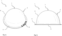
- Figure 1a is a perspective view of a portion capsule 1 according to an exemplary first embodiment of the present invention.
- the portion capsule 1 is intended for use in a beverage preparation machine for preparing a beverage, in particular by passing a liquid through the portion capsule 1. Such use is described in connection with Figure 3 be described.
- Figure 1b a side view of the portion capsule 1 according to the exemplary first embodiment of the present invention.
- the portion capsule 1 has a base element 2.
- the base element 2 comprises a capsule wall 6 (also referred to as capsule (side) wall or side wall).
- the capsule wall 6 extends from a base area 7 (also referred to as capsule base) to a circumferential flange 5, which protrudes laterally and is in particular circumferential.
- the base area 7 preferably merges smoothly into the capsule wall 6.
- the base element 2 is essentially hemispherical.
- the base element 2 spans a cavity which is intended to accommodate raw beverage material, for example roasted and ground coffee.
- the base element On the side facing away from the base area 7, the base element has a filling opening through which the cavity can be filled with the raw beverage material.
- portion capsule 1 involves rotating the portion capsule 1 about its central axis A running through the middle of the portion capsule 1.
- portion capsule 1 and in particular the base element 2 are preferably designed to be rotationally symmetrical about the central axis A.
- the capsule wall 6 extends around the cavity between the base region 7 and the flange 5.
- the flange 5 which is circular and thus runs all the way around in the circumferential direction, protrudes outwards beyond the capsule wall 6.
- the flange 5 is usually firmly connected to a cover element (also referred to as a capsule lid or membrane), here for example in the form of a particularly circular cover film 3, wherein the cover film 3 closes the cavity on the open side of the base element 2, preferably hermetically.
- the flange 5 preferably has a sealing plane facing the cover film 3, which extends essentially at right angles to the central axis A.
- the cover film 3 is sealed, welded or glued in its edge region to the flange 5 and in particular to the sealing plane, i.e. is integrally connected to it.
- the cavity is filled with the beverage raw material, for example coffee roast granules, roasted and ground coffee powder, instant coffee, chocolate powder, tea blend, milk powder and/or the like (for reasons of clarity, the beverage raw material is not illustrated) and is hermetically sealed by the lid film 3.
- the beverage raw material for example coffee roast granules, roasted and ground coffee powder, instant coffee, chocolate powder, tea blend, milk powder and/or the like (for reasons of clarity, the beverage raw material is not illustrated) and is hermetically sealed by the lid film 3.
- the portion capsule 1 comprises an optically detectable identification code, which is embodied here as a barcode 8 by way of example.
- This identification code is usually provided on the underside, i.e. on the side of the flange 5 facing away from the cover film 3 and/or the side facing the base region 7.
- the barcode 8 is a bar code.
- the barcode 8 can, as indicated here, be provided only in one circumferential section, it can be provided in several circumferential regions that are preferably evenly spaced from one another, or it can be provided all the way around.
- the barcode 8 is preferably printed, embossed or generated in some other way that enables optical detection by an (optical) detector of the beverage preparation machine.
- the portion capsule 1 is oriented in such a way that the flange underside points upwards in the plane of the drawing, ie the portion capsule 1 is shown lying on the cover foil 3.
- a common manufacturing process for such a portion capsule provides, for example, that the barcode 8 is printed on the underside of the flange and before or after that the cover film 3 is sealed to the flange 5.
- the sealing can immediately destroy or damage the barcode 8 and/or the flange is impaired in such a way, for example by mechanical action, heat, pressure and/or radiation, that the structural quality, for example the surface roughness, of the flange is adversely affected. This puts error-free detection of the barcode 8 at risk.
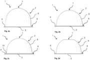
- FIGS 2a -d show schematic side views of a portion capsule 1 according to various exemplary embodiments of the present invention.
- the advantage of preparing a beverage by centrifugation is that, technically, the flange and lid film area of the portion capsule 1 are particularly important, but the shape of the base element 2 can be chosen largely freely. This enables a large number of different sizes, ie extensions of the portion capsule 1 along the central axis A. This results in different capacity volumes of the respective cavities. This enables, for example, different beverages and/or beverage intensities.
- the Figures 2a and 2b show, for example, two embodiments with essentially similarly shaped base elements 2, but different axial lengths and therefore different volumes.
- the base element 2, in particular the bottom region 7 and at least parts of the capsule wall 6, are essentially hemispherical.
- the portion capsule 1 shown has a base element which has a substantially straight and in particular perpendicular capsule wall section adjacent to the flange 5.
- the Figure 2c The portion capsule 1 shown in turn has a step 10 between the capsule wall 6 and the flange 5. This step 10 is preferably part of the capsule wall 6.
- an embodiment is shown in which the base region 7 is flat.
- the base region 7 thus comprises a main extension plane which is preferably aligned parallel to the main extension plane of the flange 5 and/or the cover film 3.
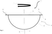
- FIG 3 is a schematic diagram of the use of a portion capsule 1 in a beverage preparation machine for preparing beverages according to an exemplary embodiment of the present invention.
- the portion capsule 1 is intended to be inserted into a brewing unit of a beverage preparation machine in order to produce a beverage.
- the brewing unit comprises a first brewing chamber part and a second brewing chamber part, wherein the first and second brewing chamber parts are movable, in particular pivotable or displaceable, relative to one another between an approximate position in which the first and second brewing chamber parts form a closed brewing chamber and an open position in which the first and second brewing chamber parts are spaced apart from one another for inserting or ejecting the portion capsule 1.
- beverage preparations are also included and meant which does not include brewing and/or extraction in the narrow sense.
- dissolving with warm and/or cold water is also included.
- a portion capsule 1 is inserted into the brewing unit in the open position and the brewing unit is closed.
- a first piercing means is moved in a central area, preferably exactly in the middle, ie in extension of the central axis A, from a retracted position to an extended position.
- the first piercing means pierces the cover film 3.
- the beverage preparation machine and its components are not shown in the figures .
- the first piercing means preferably comprises a hollow needle and/or an injection needle through which a liquid, in particular heated water under pressure, for example between 5 and 20 bar, is injected into the cavity.
- a liquid in particular heated water under pressure, for example between 5 and 20 bar
- the liquid also referred to as brewing liquid
- a second piercing means which preferably comprises at least one piercing knife, in particular a plurality of piercing knives arranged in a ring, which are arranged in particular substantially along a circular ring in the vicinity of the flange 5, are moved from a retracted position to an extended position so that they locally sever the lid film to form beverage outlet openings, and are moved back to the retracted position so as not to block the beverage outlet openings.
- the portion capsule 1 and/or the brewing unit is now rotated about the central axis A, preferably by a drive such as an electric motor.
- a drive such as an electric motor.
- the liquid and/or the beverage is thrown outwards by centrifugal forces towards the capsule wall 6 and then upwards along the capsule wall 6.
- the finished beverage then exits through the beverage outlet openings and can be directed towards a beverage outlet of the beverage preparation machine.
- the bottom region 7 can be perforated in the closed position to create a perforation opening for introducing liquid or for discharging the produced beverage.
- An optional filter medium can be used to filter any particles of the beverage raw material out of the beverage and retain them in the portion capsule 1.
- the lid film 3, which is particularly perforated multiple times, functions as a filter element.
- the portion capsule 1 now has an identification code that can be optically detected, in particular by a detector of the beverage preparation machine.
- This identification code is preferably used to identify the portion capsule 1 in the beverage preparation machine and/or to control brewing parameters.
- the beverage preparation machine can thus, for example, verify whether the portion capsule 1 in the brewing chamber is a compatible portion capsule 1 and/or automatically select and start a suitable brewing program for the beverage raw material in the portion capsule 1. It is also conceivable that specific brewing parameters to be used, such as the water temperature, the amount of water, the water pressure and/or the rotation speed of the portion capsule 1 during brewing, are embedded in the optically detectable identification code and read out by the detector.
- the optically detectable identification code is in particular a machine-readable code in the form of a one-dimensional or multi-dimensional bit or barcode 8.
- the bit or barcode 8 is designed to be completely or partially circumferential as a circle or partial circle around the central axis A of the portion capsule 1.
- the individual adjacent lines from which the bit or barcode 8, in particular two- or multi-colored, is constructed then preferably extend in the radial direction and are arranged next to one another in the circumferential direction.
- the barcode 8 is arranged in particular on a side (also referred to as the underside) of the flange 5 which faces away from the cover element, here in particular the cover film 3.
- the base element 2 and the cover film 3 are preferably made of aluminum (AI), polyethylene (PE), polypropylene (PP), polyvinyl chloride (PVC), polymethyl methacrylate (PMMA), polycarbonate (PC), polystyrene (PS), polyphenylene ether (PPO) and/or polyethylene terephthalate (PET), in particular in one or more layers.
- the pot-shaped or spherical design of the base element 2 is preferably produced by thermoforming, for example deep drawing using negative pressure, positive pressure and/or a movable stamp.
- the portion capsule is produced by injection molding, in particular using a single-component, multi-component or in-mold process.
- the base element 2 and/or the cover film 3 is made completely or partially from a biodegradable material, in particular from cellulose fibers, which are preferably embedded in a resin matrix.
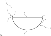
- FIG 4 a schematic cross section of a portion capsule 1 according to an exemplary second embodiment of the present invention is shown.
- the cover film 3 is not attached to the flange 5, but to the inside of the capsule wall 6.
- This is particularly preferably done by (ultrasonic) sealing, for example with a sonotrode, which inserts the cover film 3 into the cavity a little way, whereby an edge area of the cover film 3 clings to the capsule wall 6 during insertion, and then the cover film 3 is laterally sealed to the capsule wall 6.
- the sealing takes place in particular in at least one fastening area 9. This is preferably provided all the way around.
- the fastening area 9 is now arranged above the main extension plane of the cover film 3.
- the barcode 8 can be provided in the usual way on the underside of the flange, since the flange 5 is not affected by the fastening of the cover film 3.
- FIG 5 another schematic cross-section of a portion capsule 1 according to an exemplary third embodiment of the present invention is shown, whereby this third embodiment is similar to the second embodiment.
- the cover film 3 is attached laterally to an inner side of the capsule wall 6.
- the attachment area 9 is arranged below the main extension plane of the cover film 3.
- the cover film can be fixed, for example, from the outside through the capsule wall 6.
- an edge area of the cover film is bent over before insertion into the base element 2 and, for example, coated with an adhesive and inserted.
- the adhesive - or an alternative material-bonded connecting means - is activated from the outside by the application of energy, for example targeted heating and/or irradiation.
- the portion capsules 1 according to the embodiments of the Figures 4 and 5 have the disadvantage that the fastening height of the cover film 3 is difficult to control. However, this is disadvantageous because a secure piercing by the first and/or the second piercing means is not possible. can be guaranteed. Therefore, in Figure 6 a schematic cross section of a portion capsule 1 according to an exemplary fourth embodiment of the present invention is shown.
- the base element 2 has a step 10 in the capsule wall 6 below the flange 5.
- This step 10 advantageously makes it possible to ensure exact positioning of the lid film 3.
- the step 10 has a circumferential shoulder that is essentially parallel to the flange 5, i.e.
- the lid film 3 is particularly preferably attached laterally to the vertical capsule wall region, in particular sealed. I.e. the attachment region 9 is at least partially provided in the vertical capsule wall region. Additionally or alternatively, attachment can also be made to the horizontal shoulder.
- the barcode 8 can be arranged on the underside of the flange. In addition, however, exact positioning of the lid film 3 is advantageously possible via the dimensioning of the step 10.
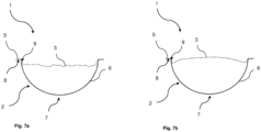
- FIGs 7a -b show schematic cross sections of a portion capsule 1 according to an exemplary fifth embodiment of the present invention at two different times during the production of the portion capsule 1.
- the situation is shown immediately before and/or after the fastening of the cover film 3.
- the cover film is fastened in an edge area on the inside of the capsule wall 6.
- the cover film 3 is now, however, particularly elastic and/or has a material reservoir. This is to be understood in particular to mean that the cover film is not taut when fastened.
- a local inner diameter of the portion capsule 1 is defined. This also results in a cross-sectional area at this point.
- the cover film 3 now has in particular an effective area that is larger than this cross-sectional area.
- This embodiment is particularly suitable for beverage raw materials that emit gases after the portion capsule 1 has been filled, for example roasted and ground coffee.
- gases for example roasted and ground coffee.
- carbon dioxide is produced by chemical processes in the coffee. This then leads to a curvature of the lid film 3, ie the lid film 3 is curved outwards by the gas produced.
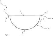
- FIG 8 a schematic cross section of a portion capsule 1 according to an exemplary sixth embodiment of the present invention is shown. In comparison to the previously explained embodiments, this provides a different fastening region 9.
- the portion capsule 1 comprises a ring element 11, i.e. a preferably ring-shaped, circumferential element which is arranged essentially at the height (in the radial direction) of the flange 5.
- This ring element 11 can, for example, be part of the lid element.
- the ring element 11 can be formed in one or more pieces with the lid element. It is preferably formed at least partially from the same material.
- the ring element 11 can have a variety of possible (radial) cross-sections, but a rectangular, square, circular, elliptical or oval cross-section is preferred.
- a cover film 3 is stretched inside the ring element 11.
- the ring element 11 has a smaller diameter than the cover film 3 or the cover element and is inserted therein.
- the cover element is connected to the flange 5 via the ring element 11. That is, the ring element 11 is attached to the flange 5.
- the ring element 5 is made, for example, from a comparatively soft material, at least in the attachment area.
- the cover element is therefore only attached indirectly to the flange 5 and the ring element 11 is designed in particular in such a way that attachment is gentle on the material.
- the flange 5 is therefore not affected or at least is affected to a significantly lesser extent.
- the barcode 8 can therefore be attached again to the underside of the flange since it is attached indirectly via the ring element 11.
- the ring element 11 can be designed in such a way that it absorbs deformation energy and thus structural damage to the barcode 8 and/or the flange 5 can be avoided.
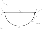
- FIG 9 is a schematic cross-section of a portion capsule 1 according to an exemplary seventh embodiment of the present invention, which corresponds to the one described above in connection with Figure 8 explained embodiment.
- the portion capsule 1 comprises a ring element 11.
- this ring element 11 now has a diameter that is larger than the diameter of the flange 5.
- the flange 5 here preferably also has a smaller diameter than in the case of generic portion capsules 1.
- the barcode 8 is provided on the ring element 11, in particular on its underside.
- the cover element for example a cover film 3, can therefore be attached to the flange 5, whereby the attachment area 9 essentially coincides with the top of the flange.
- the cover film 3 is particularly preferably firmly connected to the ring element 11, in particular made in one piece with it.
- the ring element 11 most preferably has a largely horizontal surface on its underside, at least in the area in which the barcode 8 is arranged.
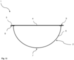
- FIG 10 a schematic cross section of a portion capsule 1 according to an exemplary eighth embodiment of the present invention is shown.
- the lid film 3 has a significantly larger diameter than the flange 5.
- the lid film 3 is placed on the flange 5 and folded over so that the lid film 3 also rests on the underside of the flange 5.
- the lid film 3 can now be connected to the flange 5 on the underside and/or the top side of the flange 5.
- the barcode 3 is printed on the lid film 3 in such a way that after the lid film 3 has been attached, the barcode is oriented on the underside of the flange and in the direction of the base region 7.
- FIG 11 a schematic cross section of a portion capsule 1 according to an exemplary ninth embodiment of the present invention is shown.
- the portion capsule 1 additionally comprises a border element 12.
- This is provided, for example, in the form of a sleeve, for example with an approximately U-shaped cross section, and is slipped over the flange 5 from the outside, so that it at least partially covers the flange 5 on the underside and at least partially covers the cover film 3 on the top.
- the border element is now fixed in such a way that it holds the cover film 3 and the flange 5 in their relative Position to each other. Flange 5 and cover film 3 are thus indirectly connected to each other.
- the edging element 12 is provided as a shrink film covering made of a suitable plastic film. After application, the edging element 12 is shrunk and thus adheres firmly to flange 5 and cover film 3.
- the edging element 12 is now transparent at least on the underside of the flange, so that the detector can detect a barcode 8 provided on the underside of the flange through the edging element 12, and/or the barcode 8 is provided on the underside of the edging element 12. Because the flange 5 and the cover film 3 are not directly connected to one another, there is no risk of damage to the flange 5 or the barcode 8, so that the barcode 8 can also be arranged safely on the underside of the flange.
- FIG 12 a schematic cross section of a portion capsule 1 according to an exemplary tenth embodiment of the present invention is shown.
- the portion capsule 1 of this embodiment does not have a lid film 3 in the narrower sense, ie no largely flexible film, but rather an at least partially and/or at least regionally rigid lid element 4.
- the lid element 4 is flexible and/or elastic enough at least in the piercing areas to ensure that the piercing means function correctly, but has sufficient inherent stability, particularly in the radially outer area, that an area of the lid element 4 not mounted on the flange 5 maintains an essentially horizontal position.
- the barcode 8 is provided here on the underside of the lid element 4, particularly in an area protruding beyond the flange 5.
- the cover element 4 can now be attached to the flange 5 in the usual way, since the radially outer barcode 8 is not affected by the attachment. It is also possible that other attachment methods can be used due to the relatively stiff cover element compared to a film. For example, the cover element 4 is glued to the flange 5.
- Figure 13 is a schematic cross-section of a portion capsule 1 according to an exemplary eleventh embodiment of the present invention. This embodiment corresponds in particular largely to the previously explained embodiment, which is shown in Figure 12 is shown.
- a cover element 4 is provided which is largely inherently stable or rigid at least in a radially outer region.
- the flange 5 now comprises not only a region which projects radially outwards, but also a region which projects radially inwards, i.e. a region pointing in the direction of the cavity. This can be created during the manufacture of the base element 2. Alternatively or additionally, it is created by the action of energy during the fastening of the cover element 4 to the flange 5.
- the inner flange region preferably has a different shape and/or a different radial extension than the outer flange region. For example, under the influence of pressure and/or heat, the material of the flange is softened in such a way that part is displaced radially inwards.
- Such a widened flange advantageously offers a larger fastening surface and thus a more stable fastening of the cover element 3 to the flange 5 and thus to the base element 2.
- the barcode 8 is particularly preferably provided on the underside of the cover element 4 in an area that projects radially outward beyond the flange 5. Since in the present case the flange 5 can be significantly deformed, it is particularly advantageous if the barcode 8 is not arranged on the flange 5, but on the cover element 4.
Landscapes
- Engineering & Computer Science (AREA)
- Mechanical Engineering (AREA)
- Food Science & Technology (AREA)
- Apparatus For Making Beverages (AREA)
- Packages (AREA)
Applications Claiming Priority (3)
| Application Number | Priority Date | Filing Date | Title |
|---|---|---|---|
| DE102022201481 | 2022-02-11 | ||
| EP23701020.2A EP4476148A1 (fr) | 2022-02-11 | 2023-01-16 | Capsule-dosette pour la préparation d'une boisson à l'aide d'une machine de préparation de boissons, système de préparation de boissons et procédé de fabrication d'une capsule-dosette |
| PCT/EP2023/050895 WO2023151902A1 (fr) | 2022-02-11 | 2023-01-16 | Capsule-dosette pour la préparation d'une boisson à l'aide d'une machine de préparation de boissons, système de préparation de boissons et procédé de fabrication d'une capsule-dosette |
Related Parent Applications (2)
| Application Number | Title | Priority Date | Filing Date |
|---|---|---|---|
| EP23701020.2A Division-Into EP4476148A1 (fr) | 2022-02-11 | 2023-01-16 | Capsule-dosette pour la préparation d'une boisson à l'aide d'une machine de préparation de boissons, système de préparation de boissons et procédé de fabrication d'une capsule-dosette |
| EP23701020.2A Division EP4476148A1 (fr) | 2022-02-11 | 2023-01-16 | Capsule-dosette pour la préparation d'une boisson à l'aide d'une machine de préparation de boissons, système de préparation de boissons et procédé de fabrication d'une capsule-dosette |
Publications (2)
| Publication Number | Publication Date |
|---|---|
| EP4516695A2 true EP4516695A2 (fr) | 2025-03-05 |
| EP4516695A3 EP4516695A3 (fr) | 2025-05-14 |
Family
ID=85018770
Family Applications (5)
| Application Number | Title | Priority Date | Filing Date |
|---|---|---|---|
| EP24210219.2A Pending EP4491538A3 (fr) | 2022-02-11 | 2023-01-16 | Capsule dosette pour la préparation d'une boisson à l'aide d'une machine de préparation de boissons, système de préparation de boissons et procédé de fabrication d'une capsule |
| EP23701020.2A Pending EP4476148A1 (fr) | 2022-02-11 | 2023-01-16 | Capsule-dosette pour la préparation d'une boisson à l'aide d'une machine de préparation de boissons, système de préparation de boissons et procédé de fabrication d'une capsule-dosette |
| EP25176712.5A Pending EP4596452A3 (fr) | 2022-02-11 | 2023-01-16 | Capsule dosette pour la préparation d'une boisson à l'aide d'une machine de préparation de boissons, système de préparation de boissons et procédé de fabrication d'une capsule |
| EP25176713.3A Pending EP4600177A2 (fr) | 2022-02-11 | 2023-01-16 | Capsule dosette pour la préparation d'une boisson à l'aide d'une machine de préparation de boissons, système de préparation de boissons et procédé de fabrication d'une capsule |
| EP24196795.9A Pending EP4516695A3 (fr) | 2022-02-11 | 2023-01-16 | Capsule dosette pour la préparation d'une boisson à l'aide d'une machine de préparation de boissons, système de préparation de boissons et procédé de fabrication d'une capsule |
Family Applications Before (4)
| Application Number | Title | Priority Date | Filing Date |
|---|---|---|---|
| EP24210219.2A Pending EP4491538A3 (fr) | 2022-02-11 | 2023-01-16 | Capsule dosette pour la préparation d'une boisson à l'aide d'une machine de préparation de boissons, système de préparation de boissons et procédé de fabrication d'une capsule |
| EP23701020.2A Pending EP4476148A1 (fr) | 2022-02-11 | 2023-01-16 | Capsule-dosette pour la préparation d'une boisson à l'aide d'une machine de préparation de boissons, système de préparation de boissons et procédé de fabrication d'une capsule-dosette |
| EP25176712.5A Pending EP4596452A3 (fr) | 2022-02-11 | 2023-01-16 | Capsule dosette pour la préparation d'une boisson à l'aide d'une machine de préparation de boissons, système de préparation de boissons et procédé de fabrication d'une capsule |
| EP25176713.3A Pending EP4600177A2 (fr) | 2022-02-11 | 2023-01-16 | Capsule dosette pour la préparation d'une boisson à l'aide d'une machine de préparation de boissons, système de préparation de boissons et procédé de fabrication d'une capsule |
Country Status (5)
| Country | Link |
|---|---|
| US (1) | US20250100786A1 (fr) |
| EP (5) | EP4491538A3 (fr) |
| AU (5) | AU2023217832A1 (fr) |
| CA (1) | CA3243209A1 (fr) |
| WO (1) | WO2023151902A1 (fr) |
Citations (4)
| Publication number | Priority date | Publication date | Assignee | Title |
|---|---|---|---|---|
| WO2016186488A1 (fr) | 2015-05-15 | 2016-11-24 | Koninklijke Douwe Egberts B.V. | Capsule, système pour préparer une boisson potable à partir d'une telle capsule et utilisation d'une telle capsule dans un dispositif de préparation de boisson |
| EP3023362B1 (fr) | 2010-07-22 | 2018-01-03 | K-fee System GmbH | Capsule avec moyen d'identification |
| WO2020201487A1 (fr) | 2019-04-03 | 2020-10-08 | K-Fee System Gmbh | Capsule de portion à identifiant |
| US10800600B2 (en) | 2010-05-12 | 2020-10-13 | Societe Des Produits Nestle S.A. | Capsule, system and method for preparing a beverage by centrifugation |
Family Cites Families (3)
| Publication number | Priority date | Publication date | Assignee | Title |
|---|---|---|---|---|
| PL2853182T3 (pl) * | 2013-09-30 | 2017-05-31 | Nestec S.A. | Nośnik kodu i kapsułka do przyrządzania napoju przez odwirowanie, system i sposób przyrządzania napoju przez odwirowanie |
| GB2523775B (en) * | 2014-03-04 | 2018-11-21 | Leslie Gort Barten | Coffee capsule |
| GB2528289A (en) * | 2014-07-16 | 2016-01-20 | Kraft Foods R&D Inc | A die-cut lid and associated container and method |
-
2023
- 2023-01-16 EP EP24210219.2A patent/EP4491538A3/fr active Pending
- 2023-01-16 US US18/730,428 patent/US20250100786A1/en active Pending
- 2023-01-16 EP EP23701020.2A patent/EP4476148A1/fr active Pending
- 2023-01-16 CA CA3243209A patent/CA3243209A1/fr active Pending
- 2023-01-16 EP EP25176712.5A patent/EP4596452A3/fr active Pending
- 2023-01-16 AU AU2023217832A patent/AU2023217832A1/en active Pending
- 2023-01-16 EP EP25176713.3A patent/EP4600177A2/fr active Pending
- 2023-01-16 WO PCT/EP2023/050895 patent/WO2023151902A1/fr not_active Ceased
- 2023-01-16 EP EP24196795.9A patent/EP4516695A3/fr active Pending
-
2025
- 2025-06-03 AU AU2025204103A patent/AU2025204103A1/en active Pending
- 2025-06-03 AU AU2025204105A patent/AU2025204105A1/en active Pending
- 2025-06-03 AU AU2025204104A patent/AU2025204104A1/en active Pending
- 2025-06-03 AU AU2025204102A patent/AU2025204102A1/en active Pending
Patent Citations (4)
| Publication number | Priority date | Publication date | Assignee | Title |
|---|---|---|---|---|
| US10800600B2 (en) | 2010-05-12 | 2020-10-13 | Societe Des Produits Nestle S.A. | Capsule, system and method for preparing a beverage by centrifugation |
| EP3023362B1 (fr) | 2010-07-22 | 2018-01-03 | K-fee System GmbH | Capsule avec moyen d'identification |
| WO2016186488A1 (fr) | 2015-05-15 | 2016-11-24 | Koninklijke Douwe Egberts B.V. | Capsule, système pour préparer une boisson potable à partir d'une telle capsule et utilisation d'une telle capsule dans un dispositif de préparation de boisson |
| WO2020201487A1 (fr) | 2019-04-03 | 2020-10-08 | K-Fee System Gmbh | Capsule de portion à identifiant |
Also Published As
| Publication number | Publication date |
|---|---|
| AU2025204104A1 (en) | 2025-06-26 |
| AU2023217832A1 (en) | 2024-08-29 |
| US20250100786A1 (en) | 2025-03-27 |
| EP4491538A3 (fr) | 2025-05-14 |
| EP4600177A2 (fr) | 2025-08-13 |
| CA3243209A1 (fr) | 2025-02-28 |
| AU2025204105A1 (en) | 2025-06-26 |
| EP4476148A1 (fr) | 2024-12-18 |
| EP4596452A2 (fr) | 2025-08-06 |
| WO2023151902A1 (fr) | 2023-08-17 |
| AU2025204103A1 (en) | 2025-06-26 |
| EP4596452A3 (fr) | 2026-05-06 |
| AU2025204102A1 (en) | 2025-06-26 |
| EP4491538A2 (fr) | 2025-01-15 |
| EP4516695A3 (fr) | 2025-05-14 |
Similar Documents
| Publication | Publication Date | Title |
|---|---|---|
| EP3521207B1 (fr) | Capsule de portion avec code à barres | |
| DE602004001387T2 (de) | Kartusche für Kaffee | |
| WO2015096989A1 (fr) | Capsule de portion pour préparer un produit d'infusion | |
| EP4377230B1 (fr) | Capsule pour la préparation des boissons | |
| DE102012110446A1 (de) | Portionskapsel mit einer Kennung an deren äußerem Umfang | |
| WO2019149875A2 (fr) | Capsule pour la préparation d'une boisson dans une machine de préparation de boissons, procédé de fabrication d'une capsule, machine pour la fabrication d'une capsule et procédé de préparation d'une boisson à l'aide d'une machine de préparation de boissons et d'une capsule | |
| DE602005002186T2 (de) | Kapsel, Vorrichtung und Verfahren zur Herstellung von Kaffee oder eines anderen Getränks | |
| EP4516695A2 (fr) | Capsule dosette pour la préparation d'une boisson à l'aide d'une machine de préparation de boissons, système de préparation de boissons et procédé de fabrication d'une capsule | |
| WO2017042290A1 (fr) | Capsule pour la préparation d'une boisson dans une machine de préparation de boissons | |
| EP3606389A1 (fr) | Adaptateur destiné à être utilisé dans une machine à capsules et système | |
| DE102010044251A1 (de) | Portionskapsel mit Kennung | |
| EP3310693B1 (fr) | Capsule pour la production des boissons | |
| WO2023147987A1 (fr) | Capsule servant à préparer une boisson au moyen d'une machine de préparation de boissons et utilisation d'une capsule | |
| EP4377227A1 (fr) | Capsule servant à préparer une boisson à l'aide d'une machine de préparation de boissons et utilisation d'une capsule | |
| EP3307648A1 (fr) | Capsule, système et procédé de production d'une boisson | |
| EP4716664A2 (fr) | Capsule-dosette pour la préparation d'une boisson au moyen d'une machine de préparation de boissons, système de préparation de boissons et procédé de fabrication d'une capsule-dosette | |
| EP3863479A1 (fr) | Élément d'étanchéité pour récipients, en particulier capsules de café | |
| DE102018200813A1 (de) | Kapsel sowie Verfahren zur Zubereitung eines Getränks | |
| EP4377228A1 (fr) | Capsule servant à préparer une boisson à l'aide d'une machine de préparation de boissons et utilisation d'une capsule | |
| EP4377229A1 (fr) | Capsule servant à préparer une boisson à l'aide d'une machine de préparation de boissons et utilisation d'une capsule |
Legal Events
| Date | Code | Title | Description |
|---|---|---|---|
| PUAI | Public reference made under article 153(3) epc to a published international application that has entered the european phase |
Free format text: ORIGINAL CODE: 0009012 |
|
| STAA | Information on the status of an ep patent application or granted ep patent |
Free format text: STATUS: THE APPLICATION HAS BEEN PUBLISHED |
|
| AC | Divisional application: reference to earlier application |
Ref document number: 4476148 Country of ref document: EP Kind code of ref document: P |
|
| AK | Designated contracting states |
Kind code of ref document: A2 Designated state(s): AL AT BE BG CH CY CZ DE DK EE ES FI FR GB GR HR HU IE IS IT LI LT LU LV MC ME MK MT NL NO PL PT RO RS SE SI SK SM TR |
|
| PUAL | Search report despatched |
Free format text: ORIGINAL CODE: 0009013 |
|
| AK | Designated contracting states |
Kind code of ref document: A3 Designated state(s): AL AT BE BG CH CY CZ DE DK EE ES FI FR GB GR HR HU IE IS IT LI LT LU LV MC ME MK MT NL NO PL PT RO RS SE SI SK SM TR |
|
| RIC1 | Information provided on ipc code assigned before grant |
Ipc: B65D 85/804 20060101AFI20250409BHEP |
|
| STAA | Information on the status of an ep patent application or granted ep patent |
Free format text: STATUS: REQUEST FOR EXAMINATION WAS MADE |
|
| 17P | Request for examination filed |
Effective date: 20251114 |