EP4516955A2 - Acier ayant des propriétés de traitement améliorées pour le formage à température élevée - Google Patents
Acier ayant des propriétés de traitement améliorées pour le formage à température élevée Download PDFInfo
- Publication number
- EP4516955A2 EP4516955A2 EP24218825.8A EP24218825A EP4516955A2 EP 4516955 A2 EP4516955 A2 EP 4516955A2 EP 24218825 A EP24218825 A EP 24218825A EP 4516955 A2 EP4516955 A2 EP 4516955A2
- Authority
- EP
- European Patent Office
- Prior art keywords
- sheet metal
- temperature
- metal part
- flat steel
- steel product
- Prior art date
- Legal status (The legal status is an assumption and is not a legal conclusion. Google has not performed a legal analysis and makes no representation as to the accuracy of the status listed.)
- Pending
Links
Images

Classifications
-
- C—CHEMISTRY; METALLURGY
- C21—METALLURGY OF IRON
- C21D—MODIFYING THE PHYSICAL STRUCTURE OF FERROUS METALS; GENERAL DEVICES FOR HEAT TREATMENT OF FERROUS OR NON-FERROUS METALS OR ALLOYS; MAKING METAL MALLEABLE, e.g. BY DECARBURISATION OR TEMPERING
- C21D1/00—General methods or devices for heat treatment, e.g. annealing, hardening, quenching or tempering
- C21D1/18—Hardening; Quenching with or without subsequent tempering
-
- C—CHEMISTRY; METALLURGY
- C21—METALLURGY OF IRON
- C21D—MODIFYING THE PHYSICAL STRUCTURE OF FERROUS METALS; GENERAL DEVICES FOR HEAT TREATMENT OF FERROUS OR NON-FERROUS METALS OR ALLOYS; MAKING METAL MALLEABLE, e.g. BY DECARBURISATION OR TEMPERING
- C21D1/00—General methods or devices for heat treatment, e.g. annealing, hardening, quenching or tempering
- C21D1/26—Methods of annealing
- C21D1/28—Normalising
-
- C—CHEMISTRY; METALLURGY
- C21—METALLURGY OF IRON
- C21D—MODIFYING THE PHYSICAL STRUCTURE OF FERROUS METALS; GENERAL DEVICES FOR HEAT TREATMENT OF FERROUS OR NON-FERROUS METALS OR ALLOYS; MAKING METAL MALLEABLE, e.g. BY DECARBURISATION OR TEMPERING
- C21D1/00—General methods or devices for heat treatment, e.g. annealing, hardening, quenching or tempering
- C21D1/62—Quenching devices
- C21D1/673—Quenching devices for die quenching
-
- C—CHEMISTRY; METALLURGY
- C21—METALLURGY OF IRON
- C21D—MODIFYING THE PHYSICAL STRUCTURE OF FERROUS METALS; GENERAL DEVICES FOR HEAT TREATMENT OF FERROUS OR NON-FERROUS METALS OR ALLOYS; MAKING METAL MALLEABLE, e.g. BY DECARBURISATION OR TEMPERING
- C21D6/00—Heat treatment of ferrous alloys
- C21D6/005—Heat treatment of ferrous alloys containing Mn
-
- C—CHEMISTRY; METALLURGY
- C21—METALLURGY OF IRON
- C21D—MODIFYING THE PHYSICAL STRUCTURE OF FERROUS METALS; GENERAL DEVICES FOR HEAT TREATMENT OF FERROUS OR NON-FERROUS METALS OR ALLOYS; MAKING METAL MALLEABLE, e.g. BY DECARBURISATION OR TEMPERING
- C21D6/00—Heat treatment of ferrous alloys
- C21D6/008—Heat treatment of ferrous alloys containing Si
-
- C—CHEMISTRY; METALLURGY
- C21—METALLURGY OF IRON
- C21D—MODIFYING THE PHYSICAL STRUCTURE OF FERROUS METALS; GENERAL DEVICES FOR HEAT TREATMENT OF FERROUS OR NON-FERROUS METALS OR ALLOYS; MAKING METAL MALLEABLE, e.g. BY DECARBURISATION OR TEMPERING
- C21D7/00—Modifying the physical properties of iron or steel by deformation
- C21D7/13—Modifying the physical properties of iron or steel by deformation by hot working
-
- C—CHEMISTRY; METALLURGY
- C21—METALLURGY OF IRON
- C21D—MODIFYING THE PHYSICAL STRUCTURE OF FERROUS METALS; GENERAL DEVICES FOR HEAT TREATMENT OF FERROUS OR NON-FERROUS METALS OR ALLOYS; MAKING METAL MALLEABLE, e.g. BY DECARBURISATION OR TEMPERING
- C21D8/00—Modifying the physical properties of ferrous metals or ferrous alloys by deformation combined with, or followed by, heat treatment
- C21D8/02—Modifying the physical properties of ferrous metals or ferrous alloys by deformation combined with, or followed by, heat treatment during manufacturing of plates or strips
- C21D8/0221—Modifying the physical properties of ferrous metals or ferrous alloys by deformation combined with, or followed by, heat treatment during manufacturing of plates or strips characterised by the working steps
- C21D8/0226—Hot rolling
-
- C—CHEMISTRY; METALLURGY
- C21—METALLURGY OF IRON
- C21D—MODIFYING THE PHYSICAL STRUCTURE OF FERROUS METALS; GENERAL DEVICES FOR HEAT TREATMENT OF FERROUS OR NON-FERROUS METALS OR ALLOYS; MAKING METAL MALLEABLE, e.g. BY DECARBURISATION OR TEMPERING
- C21D8/00—Modifying the physical properties of ferrous metals or ferrous alloys by deformation combined with, or followed by, heat treatment
- C21D8/02—Modifying the physical properties of ferrous metals or ferrous alloys by deformation combined with, or followed by, heat treatment during manufacturing of plates or strips
- C21D8/0221—Modifying the physical properties of ferrous metals or ferrous alloys by deformation combined with, or followed by, heat treatment during manufacturing of plates or strips characterised by the working steps
- C21D8/0236—Cold rolling
-
- C—CHEMISTRY; METALLURGY
- C21—METALLURGY OF IRON
- C21D—MODIFYING THE PHYSICAL STRUCTURE OF FERROUS METALS; GENERAL DEVICES FOR HEAT TREATMENT OF FERROUS OR NON-FERROUS METALS OR ALLOYS; MAKING METAL MALLEABLE, e.g. BY DECARBURISATION OR TEMPERING
- C21D8/00—Modifying the physical properties of ferrous metals or ferrous alloys by deformation combined with, or followed by, heat treatment
- C21D8/02—Modifying the physical properties of ferrous metals or ferrous alloys by deformation combined with, or followed by, heat treatment during manufacturing of plates or strips
- C21D8/0247—Modifying the physical properties of ferrous metals or ferrous alloys by deformation combined with, or followed by, heat treatment during manufacturing of plates or strips characterised by the heat treatment
- C21D8/0263—Modifying the physical properties of ferrous metals or ferrous alloys by deformation combined with, or followed by, heat treatment during manufacturing of plates or strips characterised by the heat treatment following hot rolling
-
- C—CHEMISTRY; METALLURGY
- C21—METALLURGY OF IRON
- C21D—MODIFYING THE PHYSICAL STRUCTURE OF FERROUS METALS; GENERAL DEVICES FOR HEAT TREATMENT OF FERROUS OR NON-FERROUS METALS OR ALLOYS; MAKING METAL MALLEABLE, e.g. BY DECARBURISATION OR TEMPERING
- C21D8/00—Modifying the physical properties of ferrous metals or ferrous alloys by deformation combined with, or followed by, heat treatment
- C21D8/02—Modifying the physical properties of ferrous metals or ferrous alloys by deformation combined with, or followed by, heat treatment during manufacturing of plates or strips
- C21D8/04—Modifying the physical properties of ferrous metals or ferrous alloys by deformation combined with, or followed by, heat treatment during manufacturing of plates or strips to produce plates or strips for drawing, e.g. for deep-drawing
-
- C—CHEMISTRY; METALLURGY
- C21—METALLURGY OF IRON
- C21D—MODIFYING THE PHYSICAL STRUCTURE OF FERROUS METALS; GENERAL DEVICES FOR HEAT TREATMENT OF FERROUS OR NON-FERROUS METALS OR ALLOYS; MAKING METAL MALLEABLE, e.g. BY DECARBURISATION OR TEMPERING
- C21D8/00—Modifying the physical properties of ferrous metals or ferrous alloys by deformation combined with, or followed by, heat treatment
- C21D8/02—Modifying the physical properties of ferrous metals or ferrous alloys by deformation combined with, or followed by, heat treatment during manufacturing of plates or strips
- C21D8/04—Modifying the physical properties of ferrous metals or ferrous alloys by deformation combined with, or followed by, heat treatment during manufacturing of plates or strips to produce plates or strips for drawing, e.g. for deep-drawing
- C21D8/0421—Modifying the physical properties of ferrous metals or ferrous alloys by deformation combined with, or followed by, heat treatment during manufacturing of plates or strips to produce plates or strips for drawing, e.g. for deep-drawing characterised by the working steps
-
- C—CHEMISTRY; METALLURGY
- C21—METALLURGY OF IRON
- C21D—MODIFYING THE PHYSICAL STRUCTURE OF FERROUS METALS; GENERAL DEVICES FOR HEAT TREATMENT OF FERROUS OR NON-FERROUS METALS OR ALLOYS; MAKING METAL MALLEABLE, e.g. BY DECARBURISATION OR TEMPERING
- C21D8/00—Modifying the physical properties of ferrous metals or ferrous alloys by deformation combined with, or followed by, heat treatment
- C21D8/02—Modifying the physical properties of ferrous metals or ferrous alloys by deformation combined with, or followed by, heat treatment during manufacturing of plates or strips
- C21D8/04—Modifying the physical properties of ferrous metals or ferrous alloys by deformation combined with, or followed by, heat treatment during manufacturing of plates or strips to produce plates or strips for drawing, e.g. for deep-drawing
- C21D8/0421—Modifying the physical properties of ferrous metals or ferrous alloys by deformation combined with, or followed by, heat treatment during manufacturing of plates or strips to produce plates or strips for drawing, e.g. for deep-drawing characterised by the working steps
- C21D8/0436—Cold rolling
-
- C—CHEMISTRY; METALLURGY
- C21—METALLURGY OF IRON
- C21D—MODIFYING THE PHYSICAL STRUCTURE OF FERROUS METALS; GENERAL DEVICES FOR HEAT TREATMENT OF FERROUS OR NON-FERROUS METALS OR ALLOYS; MAKING METAL MALLEABLE, e.g. BY DECARBURISATION OR TEMPERING
- C21D8/00—Modifying the physical properties of ferrous metals or ferrous alloys by deformation combined with, or followed by, heat treatment
- C21D8/02—Modifying the physical properties of ferrous metals or ferrous alloys by deformation combined with, or followed by, heat treatment during manufacturing of plates or strips
- C21D8/04—Modifying the physical properties of ferrous metals or ferrous alloys by deformation combined with, or followed by, heat treatment during manufacturing of plates or strips to produce plates or strips for drawing, e.g. for deep-drawing
- C21D8/0447—Modifying the physical properties of ferrous metals or ferrous alloys by deformation combined with, or followed by, heat treatment during manufacturing of plates or strips to produce plates or strips for drawing, e.g. for deep-drawing characterised by the heat treatment
- C21D8/0457—Modifying the physical properties of ferrous metals or ferrous alloys by deformation combined with, or followed by, heat treatment during manufacturing of plates or strips to produce plates or strips for drawing, e.g. for deep-drawing characterised by the heat treatment with diffusion of elements, e.g. decarburising, nitriding
-
- C—CHEMISTRY; METALLURGY
- C21—METALLURGY OF IRON
- C21D—MODIFYING THE PHYSICAL STRUCTURE OF FERROUS METALS; GENERAL DEVICES FOR HEAT TREATMENT OF FERROUS OR NON-FERROUS METALS OR ALLOYS; MAKING METAL MALLEABLE, e.g. BY DECARBURISATION OR TEMPERING
- C21D8/00—Modifying the physical properties of ferrous metals or ferrous alloys by deformation combined with, or followed by, heat treatment
- C21D8/02—Modifying the physical properties of ferrous metals or ferrous alloys by deformation combined with, or followed by, heat treatment during manufacturing of plates or strips
- C21D8/04—Modifying the physical properties of ferrous metals or ferrous alloys by deformation combined with, or followed by, heat treatment during manufacturing of plates or strips to produce plates or strips for drawing, e.g. for deep-drawing
- C21D8/0447—Modifying the physical properties of ferrous metals or ferrous alloys by deformation combined with, or followed by, heat treatment during manufacturing of plates or strips to produce plates or strips for drawing, e.g. for deep-drawing characterised by the heat treatment
- C21D8/0463—Modifying the physical properties of ferrous metals or ferrous alloys by deformation combined with, or followed by, heat treatment during manufacturing of plates or strips to produce plates or strips for drawing, e.g. for deep-drawing characterised by the heat treatment following hot rolling
-
- C—CHEMISTRY; METALLURGY
- C21—METALLURGY OF IRON
- C21D—MODIFYING THE PHYSICAL STRUCTURE OF FERROUS METALS; GENERAL DEVICES FOR HEAT TREATMENT OF FERROUS OR NON-FERROUS METALS OR ALLOYS; MAKING METAL MALLEABLE, e.g. BY DECARBURISATION OR TEMPERING
- C21D8/00—Modifying the physical properties of ferrous metals or ferrous alloys by deformation combined with, or followed by, heat treatment
- C21D8/02—Modifying the physical properties of ferrous metals or ferrous alloys by deformation combined with, or followed by, heat treatment during manufacturing of plates or strips
- C21D8/04—Modifying the physical properties of ferrous metals or ferrous alloys by deformation combined with, or followed by, heat treatment during manufacturing of plates or strips to produce plates or strips for drawing, e.g. for deep-drawing
- C21D8/0478—Modifying the physical properties of ferrous metals or ferrous alloys by deformation combined with, or followed by, heat treatment during manufacturing of plates or strips to produce plates or strips for drawing, e.g. for deep-drawing involving a particular surface treatment
-
- C—CHEMISTRY; METALLURGY
- C21—METALLURGY OF IRON
- C21D—MODIFYING THE PHYSICAL STRUCTURE OF FERROUS METALS; GENERAL DEVICES FOR HEAT TREATMENT OF FERROUS OR NON-FERROUS METALS OR ALLOYS; MAKING METAL MALLEABLE, e.g. BY DECARBURISATION OR TEMPERING
- C21D9/00—Heat treatment, e.g. annealing, hardening, quenching or tempering, adapted for particular articles; Furnaces therefor
- C21D9/46—Heat treatment, e.g. annealing, hardening, quenching or tempering, adapted for particular articles; Furnaces therefor for sheet metals
- C21D9/48—Heat treatment, e.g. annealing, hardening, quenching or tempering, adapted for particular articles; Furnaces therefor for sheet metals deep-drawing sheets
-
- C—CHEMISTRY; METALLURGY
- C22—METALLURGY; FERROUS OR NON-FERROUS ALLOYS; TREATMENT OF ALLOYS OR NON-FERROUS METALS
- C22C—ALLOYS
- C22C38/00—Ferrous alloys, e.g. steel alloys
- C22C38/002—Ferrous alloys, e.g. steel alloys containing In, Mg, or other elements not provided for in one single group C22C38/001 - C22C38/60
-
- C—CHEMISTRY; METALLURGY
- C22—METALLURGY; FERROUS OR NON-FERROUS ALLOYS; TREATMENT OF ALLOYS OR NON-FERROUS METALS
- C22C—ALLOYS
- C22C38/00—Ferrous alloys, e.g. steel alloys
- C22C38/02—Ferrous alloys, e.g. steel alloys containing silicon
-
- C—CHEMISTRY; METALLURGY
- C22—METALLURGY; FERROUS OR NON-FERROUS ALLOYS; TREATMENT OF ALLOYS OR NON-FERROUS METALS
- C22C—ALLOYS
- C22C38/00—Ferrous alloys, e.g. steel alloys
- C22C38/04—Ferrous alloys, e.g. steel alloys containing manganese
-
- C—CHEMISTRY; METALLURGY
- C22—METALLURGY; FERROUS OR NON-FERROUS ALLOYS; TREATMENT OF ALLOYS OR NON-FERROUS METALS
- C22C—ALLOYS
- C22C38/00—Ferrous alloys, e.g. steel alloys
- C22C38/06—Ferrous alloys, e.g. steel alloys containing aluminium
-
- C—CHEMISTRY; METALLURGY
- C22—METALLURGY; FERROUS OR NON-FERROUS ALLOYS; TREATMENT OF ALLOYS OR NON-FERROUS METALS
- C22C—ALLOYS
- C22C38/00—Ferrous alloys, e.g. steel alloys
- C22C38/12—Ferrous alloys, e.g. steel alloys containing tungsten, tantalum, molybdenum, vanadium, or niobium
-
- C—CHEMISTRY; METALLURGY
- C22—METALLURGY; FERROUS OR NON-FERROUS ALLOYS; TREATMENT OF ALLOYS OR NON-FERROUS METALS
- C22C—ALLOYS
- C22C38/00—Ferrous alloys, e.g. steel alloys
- C22C38/14—Ferrous alloys, e.g. steel alloys containing titanium or zirconium
-
- C—CHEMISTRY; METALLURGY
- C23—COATING METALLIC MATERIAL; COATING MATERIAL WITH METALLIC MATERIAL; CHEMICAL SURFACE TREATMENT; DIFFUSION TREATMENT OF METALLIC MATERIAL; COATING BY VACUUM EVAPORATION, BY SPUTTERING, BY ION IMPLANTATION OR BY CHEMICAL VAPOUR DEPOSITION, IN GENERAL; INHIBITING CORROSION OF METALLIC MATERIAL OR INCRUSTATION IN GENERAL
- C23C—COATING METALLIC MATERIAL; COATING MATERIAL WITH METALLIC MATERIAL; SURFACE TREATMENT OF METALLIC MATERIAL BY DIFFUSION INTO THE SURFACE, BY CHEMICAL CONVERSION OR SUBSTITUTION; COATING BY VACUUM EVAPORATION, BY SPUTTERING, BY ION IMPLANTATION OR BY CHEMICAL VAPOUR DEPOSITION, IN GENERAL
- C23C2/00—Hot-dipping or immersion processes for applying the coating material in the molten state without affecting the shape; Apparatus therefor
- C23C2/04—Hot-dipping or immersion processes for applying the coating material in the molten state without affecting the shape; Apparatus therefor characterised by the coating material
- C23C2/12—Aluminium or alloys based thereon
-
- C—CHEMISTRY; METALLURGY
- C22—METALLURGY; FERROUS OR NON-FERROUS ALLOYS; TREATMENT OF ALLOYS OR NON-FERROUS METALS
- C22C—ALLOYS
- C22C38/00—Ferrous alloys, e.g. steel alloys
- C22C38/60—Ferrous alloys, e.g. steel alloys containing lead, selenium, tellurium, or antimony, or more than 0.04% by weight of sulfur
Definitions
- the invention relates to a flat steel product for hot forming and a method for producing such a flat steel product. Furthermore, the invention relates to a sheet metal part with improved properties and a method for producing such a sheet metal part from a flat steel product.
- the microstructure was determined on longitudinal sections that had been etched with 3% Nital (alcoholic nitric acid). The amount of retained austenite was determined by X-ray diffraction.
- the sheet metal part consists of a steel which, in addition to iron and unavoidable impurities, is composed of (in % by weight) 0.10 - 0.30% C, 0.5 - 2.0% Si, 0.5 - 2.4% Mn, 0.01 - 0.2% Al, 0.005 - 1.5% Cr, 0.01 - 0.1% P and possibly other optional elements, in particular 0.005 - 0.1% Nb.
- the sheet metal component comprises an anti-corrosion coating which contains aluminum.
- the task was to further develop a flat steel product for hot forming in such a way that, in conjunction with an aluminum-based anti-corrosion coating, improved processing properties of the hot-formed sheet metal part could be achieved.
- a process was to be specified with which such sheet metal parts could be manufactured in a practical manner.
- a flat steel product for hot forming comprising a steel substrate made of steel which, in addition to iron and unavoidable impurities (in % by weight), consists of C: 0.06 - 0.5%, Si: 0.05 - 0.6%, Mn: 0.4 - 3.0%, Al: 0.06 - 1.0%, Nb: 0.001 - 0.2%, Ti: 0.001 - 0.10% B: 0.0005 - 0.01% P: ⁇ 0.03%, S: ⁇ 0.02%, N: ⁇ 0.02%, Sn: ⁇ 0.03% Ace: ⁇ 0.01% and optionally one or more of the elements "Cr, Cu, Mo, Ni, V, Ca, W" in the following contents Cr: 0.01 - 1.0%, Cu: 0.01 - 0.2%, Mo: 0.002 - 0.3%, Ni: 0.01-0.5%, V: 0.001 - 0.3%, Ca: 0.0005 - 0.005%, W: 0.001 -1.00% consists.
- the steel substrate of the flat steel product according to the invention has an aluminum content of at least 0.06% by weight, preferably at least 0.07% by weight, in particular at least 0.08% by weight.
- the aluminum content is preferably at least 0.10% by weight, particularly preferably at least 0.11% by weight, in particular at least 0.12% by weight, preferably at least 0.140% by weight, in particular at least 0.15% by weight, preferably at least 0.16% by weight.
- the maximum aluminum content is 1.0% by weight, in particular a maximum of 0.8% by weight.
- the aluminum content is at least 0.07 wt.%, in particular at least 0.08 wt.%, preferably at least 0.10 wt.%, particularly preferably at least 0.11 wt.%, in particular at least 0.12 wt.%, preferably at least 0.140 wt.%, in particular at least 0.15 wt.%, preferably at least 0.16 wt.%.
- the maximum aluminum content in this variant is a maximum of 0.50 wt.%, in particular a maximum of 0.35 wt.%, preferably a maximum of 0.25 wt.%, in particular a maximum of 0.24 wt.%.
- the aluminum content is at least 0.50 wt.%, preferably at least 0.60 wt.%, preferably at least 0.70 wt.%.
- the maximum aluminum content in this variant is a maximum of 1.0 wt.%, in particular a maximum of 0.9 wt.%, preferably a maximum of 0.80 wt.%.
- Al is known to be added as a deoxidising agent in the production of steel. At least 0.01 wt.% Al is required to reliably bind the oxygen contained in the steel melt. Al can also be used to bind undesirable but unavoidable levels of N during production. Comparatively high aluminium contents have been avoided so far because the Ac3 temperature also shifts upwards with the aluminium content. This has a negative effect on austenitisation, which is important for hot forming. However, it has been shown that increased aluminium contents surprisingly lead to positive effects in conjunction with an aluminium-based anti-corrosion coating.
- iron-aluminide compounds with a higher density are formed via a multi-stage phase transformation (Fe2Al5 ⁇ Fe2Al ⁇ FeAl ⁇ Fe3Al).
- the formation of such denser phases is associated with a higher aluminum consumption than with less dense phases.
- This locally higher aluminum consumption leads to the formation of pores (vacancies) in the resulting phase.
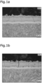
- These pores preferably form in the transition area between the steel substrate and the anti-corrosion coating, where the proportion of available aluminum is strongly influenced by the aluminum content of the steel substrate. In particular, an accumulation of pores in the form of a band can occur in the transition area.
- Al content is too high, especially if it exceeds 1.0 wt.% Al, there is a risk that Al oxides will form on the surface of a product made from steel alloyed according to the invention, which would impair the wetting behavior during hot-dip coating.
- higher Al contents promote the formation of non-metallic Al-based inclusions, which, as coarse inclusions, have a negative effect on crash behavior.
- the Al content is therefore preferably selected below the upper limits already mentioned.
- the bending behavior of the sheet metal component is particularly supported by the niobium content ("Nb") according to the invention of at least 0.001% by weight.
- the Nb content is preferably at least 0.005% by weight, in particular at least 0.010% by weight, preferably at least 0.015% by weight, particularly preferably at least 0.020% by weight, in particular at least 0.024% by weight, preferably at least 0.025% by weight.
- the specified Nb content leads, particularly in the process described below for producing a flat steel product for hot forming with a corrosion protection coating, to a distribution of niobium carbonitrides, which leads to a particularly fine hardening structure during subsequent hot forming.
- the coated flat steel product is kept in a temperature range of 400 °C and 300 °C for a certain time. In this temperature range, there is still a certain diffusion rate of carbon ("C") in the steel substrate, while the thermodynamic solubility is very low. Carbon therefore diffuses to lattice defects and collects there.
- Lattice defects are caused in particular by dissolved niobium atoms, which expand the atomic lattice due to their significantly higher atomic volume and thus enlarge the tetrahedral and octahedral gaps in the atomic lattice, so that the local solubility of C is increased.
- the refined ferritic structure in the interdiffusion layer helps reduce the tendency for cracks to initiate under bending loads.
- the higher Nb content has another advantage. Surprisingly, it has been shown that the higher Nb content in the steel substrate leads to a shift in the electrochemical potential in the final sheet metal part towards a more positive (i.e. nobler) potential.
- the Nb content in the interdiffusion layer has proven to be a good indicator of the shift in the electrochemical potential. If the Nb content in the interdiffusion layer is at least 0.010%, the potential is about 100-150 mV higher than in a comparison substrate with a lower Nb content.
- the sheet metal part thus produced therefore has a higher corrosion resistance.
- the Nb content is a maximum of 0.2 wt.%.
- the Nb content is also preferably a maximum of 0.20 wt.%, in particular a maximum of 0.15 wt.%, preferably a maximum of 0.10 wt.%, in particular a maximum of 0.05 wt.%.
- the formation of AIN is thermodynamically favoured compared to the formation of NbN or NbC.
- the precipitation of AIN has a grain-refining effect in the austenite and thus improves toughness. Increasing Al/Nb ratios improve this effect.
- the preferred ratio is Al/Nb >_ 2, especially >_ 3.
- too high a ratio of Al/Nb means that the AlN formation is no longer as fine as it would be advantageous to, but increasingly coarser AlN particles appear, which reduces the grain refinement effect. It has been shown that this effect occurs earlier at low manganese contents than at higher ones. Manganese contents, since the AC3 temperature decreases with increasing manganese content.
- the ratio Al/Nb is ⁇ 18.0, in particular ⁇ 16.0, preferably ⁇ 14.0, particularly preferably ⁇ 12.0, in particular ⁇ 10.0, preferably ⁇ 9.0, in particular ⁇ 8.0, preferably ⁇ 7.0.
- the ratio Al/Nb is ⁇ 28.0, in particular ⁇ 26.0, preferably ⁇ 24.0, particularly preferably ⁇ 22.0, preferably ⁇ 20.0, in particular ⁇ 18.0, in particular ⁇ 16.0, preferably ⁇ 14.0, particularly preferably ⁇ 12.0, in particular ⁇ 10.0, preferably ⁇ 9.0, in particular ⁇ 8.0, preferably ⁇ 7.0.
- the ratio Al/Nb is ⁇ 18.0, in particular ⁇ 16.0, preferably ⁇ 14.0, particularly preferably ⁇ 12.0, in particular ⁇ 10.0, preferably ⁇ 9.0, in particular ⁇ 8.0, preferably ⁇ 7.0.
- Carbon is contained in the steel substrate of the flat steel product in amounts of 0.06 - 0.5 wt.%. C contents adjusted in this way contribute to the hardenability of the steel by delaying the formation of ferrite and bainite and stabilizing the residual austenite in the structure. A C content of at least 0.06 wt.% is required to achieve sufficient hardenability and the associated high strength.
- the C content can be set to 0.5 wt.%, preferably to a maximum of 0.5 wt.%, in particular to a maximum of 0.45 wt.%, preferably to 0.42 wt.%, particularly preferably 0.40 wt.%, preferably a maximum of 0.38 wt.%, in particular a maximum of 0.35 wt.%.
- C contents of at least 0.10 wt.%, preferably 0.11 wt.%, in particular at least 0.15 wt.%, preferably at least 0.15 wt.% can be provided.
- tensile strengths of the sheet metal part of at least 1000 MPa, in particular at least 1100 MPa can be reliably achieved after hot press forming.
- the C content is at least 0.10 wt.%, preferably 0.11 wt.%, in particular at least 0.15 wt.%, preferably at least 0.15 wt.%.
- the maximum C content in this variant is a maximum of 0.50 wt.%, in particular a maximum of 0.25 wt.%, preferably a maximum of 0.25 wt.%.
- the C content is at least 0.25 wt.%, preferably at least 0.50 wt.%, in particular at least 0.32 wt.%.
- the maximum C content in this variant is a maximum of 0.5 wt.%, in particular a maximum of 0.50 wt.%, preferably a maximum of 0.40 wt.%, preferably a maximum of 0.38 wt.%, in particular a maximum of 0.35 wt.%.
- the C content is at least 0.50 wt.%, preferably at least 0.32 wt.%, in particular at least 0.55 wt.%, preferably at least 0.34 wt.%, preferably at least 0.35 wt.%, in particular at least 0.40 wt.%, preferably at most 0.44 wt.%.
- the maximum C content in this variant is at most 0.5 wt.%, in particular at most 0.50 wt.%, preferably at most 0.48 wt.%.
- Silicon is used to further increase the hardenability of the flat steel product and the strength of the press-hardened product via solid solution strengthening. Silicon also enables the use of ferro-silicon-manganese as an alloying agent, which has a beneficial effect on production costs. From a Si content of 0.05 wt.%, a Hardening effect occurs. A significant increase in strength occurs from a Si content of at least 0.15 wt.%, in particular at least 0.20 wt.%. Si contents above 0.6 wt.% have a detrimental effect on the coating behavior, especially in the case of Al-based coatings. Si contents of at most 0.50 wt.%, in particular at most 0.50 wt.%, are preferably set in order to improve the surface quality of the coated flat steel product.
- Manganese acts as a hardening element by significantly delaying the formation of ferrite and bainite. At manganese contents of less than 0.4 wt. %, significant amounts of ferrite and bainite are formed during press hardening, even at very fast cooling rates, which should be avoided. Mn contents of at least 0.5 wt. %, in particular at least 0.7 wt. %, preferably at least 0.8 wt. %, in particular at least 0.9 wt. %, preferably at least 1.00 wt. %, in particular at least 1.05 wt. %, particularly preferably at least 1.10 wt.
- Mn contents of more than 3.0 wt. % have a detrimental effect on the processing properties, which is why the Mn content of flat steel products according to the invention is limited to a maximum of 3.0 wt. %, preferably a maximum of 2.5 wt. %.
- weldability is severely limited, which is why the Mn content is preferably limited to a maximum of 1.6 wt.% and in particular to 1.30 wt.%, preferably to 1.20 wt.%.
- Mn contents of less than or equal to 1.6 wt.% are also preferred for economic reasons.
- Titanium is a microalloying element which is added to contribute to grain refinement, whereby at least 0.001 wt.% Ti, in particular at least 0.004 wt.%, preferably at least 0.010 wt.% Ti, should be added for sufficient availability. From 0.10 wt.% Ti, the cold rollability and recrystallizability deteriorate significantly, which is why higher Ti contents should be avoided.
- the Ti content can preferably be limited to 0.08 wt.%, in particular to 0.038 wt.%, particularly preferably to 0.020 wt.%, in particular 0.015 wt.%. Titanium also has the effect of binding nitrogen and thus enabling boron to develop its strong ferrite-inhibiting effect. Therefore, in a preferred development, the titanium content is more than 3.42 times the nitrogen content in order to achieve sufficient binding of nitrogen.
- B Boron
- the B content is limited to at most 0.01 wt.%, preferably at most 0.0100 wt.%, preferably at most 0.0050 wt.%, in particular at most 0.0035 wt.%, in particular at most 0.0050 wt.%, preferably at most 0.0025 wt.%.
- Phosphorus (“P”) and sulfur (“S”) are elements that are introduced into the steel as impurities through iron ore and cannot be completely removed in the large-scale steelworks process.
- the P content and the S content should be kept as low as possible, since the mechanical properties such as the impact energy deteriorate with increasing P content or S content. From P contents of 0.03 wt.%, embrittlement of the martensite also begins to occur, which is why the P content of a flat steel product according to the invention is limited to a maximum of 0.05 wt.%, in particular a maximum of 0.02 wt.%.
- the S content of a flat steel product according to the invention is limited to a maximum of 0.02 wt.%, preferably a maximum of 0.0010 wt.%, in particular a maximum of 0.005 wt.%.
- N Nitrogen
- the N content should be kept as low as possible and should not exceed 0.02% by weight. Nitrogen is particularly harmful to alloys that contain boron because it prevents the transformation-retarding effect of boron by forming boron nitrides, which is why the N content in this case should preferably not exceed 0.010% by weight, in particular not exceed 0.007% by weight.
- Sn tin
- As arsenic
- Sn content is a maximum of 0.05 wt.%, preferably a maximum of 0.02 wt.%.
- As content is a maximum of 0.01 wt.%, in particular a maximum of 0.005 wt.%.
- impurities P, S, N, Sn and As other elements can also be present as impurities in the steel. These other elements are listed under the "unavoidable impurities”.
- the total content of these "unavoidable impurities” is preferably a maximum of 0.2% by weight, preferably a maximum of 0.1% by weight.
- the optional alloying elements Cr, Cu, Mo, Ni, V, Ca and W described below, for which a lower limit is specified, can also occur in the steel substrate as unavoidable impurities in contents below the respective lower limit. In this case, they are also counted as "unavoidable impurities", the total content of which is limited to a maximum of 0.2% by weight, preferably a maximum of 0.1% by weight.
- Chromium, copper, molybdenum, nickel, vanadium, calcium and tungsten can optionally be added to the steel of a flat steel product according to the invention, either individually or in combination with one another.
- Chromium suppresses the formation of ferrite and pearlite during accelerated cooling of a flat steel product according to the invention and enables complete martensite formation even at lower cooling rates, thereby increasing hardenability.
- the Cr content of the steel or the steel substrate is limited to a maximum of 1.0 wt.%, preferably a maximum of 0.80 wt.%, in particular a maximum of 0.75 wt.%, preferably a maximum of 0.50 wt.%, in particular a maximum of 0.50 wt.%.
- Vanadium can optionally be added in amounts of 0.001 - 1.0 wt.%.
- the vanadium content is preferably a maximum of 0.3 wt.%. For cost reasons, a maximum of 0.2 wt.% vanadium is added.
- Copper can optionally be added to the alloy to increase hardenability with additions of at least 0.01 wt.%, preferably at least 0.010 wt.%, in particular at least 0.015 wt.%.
- copper improves the resistance to atmospheric corrosion of uncoated sheets or cut edges. If the Cu content is too high, hot rollability deteriorates significantly due to low-melting Cu phases on the surface, which is why the Cu content is limited to a maximum of 0.2 wt.%, preferably a maximum of 0.1 wt.%, in particular a maximum of 0.10 wt.%.
- Molybdenum (“Mo”) can optionally be added to improve process stability, as it significantly slows down ferrite formation. At contents of 0.002 wt.% and above, dynamic molybdenum-carbon clusters form on the grain boundaries, up to ultrafine molybdenum carbides, which significantly slow down the mobility of the grain boundary and thus diffusive phase transformations. In addition, molybdenum reduces the grain boundary energy, which reduces the nucleation rate of ferrite.
- the Mo content is preferably at least 0.004 wt.%, in particular at least 0.01 wt.%. Due to the high costs associated with an alloy of molybdenum, the Mo content should be at most 0.3 wt.%, in particular at most 0.10 wt.%, preferably at most 0.08 wt.%.
- Nickel stabilizes the austenitic phase and can optionally be added to the alloy to reduce the Ac3 temperature and suppress the formation of ferrite and bainite. Nickel also has a positive influence on hot rollability, particularly if the steel contains copper. Copper impairs hot rollability. To counteract the negative influence of copper on hot rollability, 0.01 wt.% nickel can be added to the steel; the Ni content is preferably at least 0.015 wt.%, in particular at least 0.020 wt.%. For economic reasons, the nickel content should be limited to a maximum of 0.5 wt.%, in particular a maximum of 0.20 wt.%. The Ni content is preferably a maximum of 0.10 wt.%.
- a flat steel product according to the invention can optionally contain at least 0.0005 wt.% Ca, in particular at least 0.0010 wt.%, preferably at least 0.0020 wt.%.
- the maximum Ca content is 0.01 wt.%, in particular a maximum of 0.007 wt.%, preferably a maximum of 0.005 wt.%.
- an upper limit of the Ca content of not more than 0.005 wt.%, preferably not more than 0.005 wt.%, in particular not more than 0.002 wt.%, preferably not more than 0.001 wt.% should be observed.
- Tungsten can optionally be added in amounts of 0.001 - 1.0 wt.% to slow down the formation of ferrite.
- a positive effect on hardenability is already achieved at W content of at least 0.001 wt.%.
- a maximum of 1.0 wt.% tungsten is added.
- the sum of the Mn content and the Cr content (“Mn+Cr”) is more than 0.7 wt.%, in particular more than 0.8 wt.%, preferably more than 1.1 wt.%. Below a minimum sum of both elements, their necessary transformation-inhibiting effect is lost. Irrespective of this, the sum of the Mn content and the Cr content is less than 3.5 wt.%, preferably less than 2.5 wt.%, in particular less than 2.0 wt.%, particularly preferably less than 1.5 wt.%. The upper limit values of both elements arise from ensuring the coating performance and to guarantee sufficient welding behavior.
- the flat steel product preferably comprises an anti-corrosion coating to protect the steel substrate from oxidation and corrosion during hot forming and during use of the produced steel component.
- the flat steel product preferably comprises an aluminum-based anti-corrosion coating.
- the anti-corrosion coating can be applied to one or both sides of the flat steel product.
- the two large surfaces of the flat steel product that face each other are referred to as the two sides of the flat steel product.
- the narrow surfaces are referred to as edges.
- Such a corrosion protection coating is preferably produced by hot-dip coating the flat steel product.
- the flat steel product is passed through a liquid melt which consists of 0.1 - 15 wt.% Si, preferably more than 1.0 wt.% Si, optionally 2-4 wt.% Fe, optionally up to 5 wt.% alkali or alkaline earth metals, preferably up to 1.0 wt.% alkali or alkaline earth metals, and optionally up to 15 wt.% Zn, preferably up to 10 wt.% Zn and optionally further components, the total contents of which are limited to a maximum of 2.0 wt.%, and the remainder being aluminum.
- the Si content of the melt is 1.0 - 3.5 wt.% or 5-15 wt.%, preferably 7 - 12 wt.%, in particular 8-10 wt.%.
- the optional content of alkali or alkaline earth metals in the melt comprises 0.1 - 1.0 wt.% Mg, in particular 0.1 - 0.7 wt.% Mg, preferably 0.1 - 0.5 wt.% Mg.
- the optional content of alkali or alkaline earth metals in the melt can comprise in particular at least 0.0015 wt.% Ca, in particular at least 0.01 wt.% Ca.
- the alloy layer lies on the steel substrate and is directly adjacent to it.
- the alloy layer is essentially made of aluminum and iron.
- the other elements from the steel substrate or the melt composition do not accumulate significantly in the alloy layer.
- the alloy layer preferably consists of 35-60 wt.% Fe, preferably ⁇ -iron, optional further components, the total contents of which are limited to a maximum of 5.0 wt.%, preferably 2.0%, and the remainder aluminum, with the Al content preferably increasing towards the surface.
- the optional further components include in particular the other components of the melt (i.e. silicon and optionally alkali or alkaline earth metals, in particular Mg or Ca) and the remaining portions of the steel substrate in addition to iron.
- the Al base layer lies on the alloy layer and is directly adjacent to it.
- the composition of the Al base layer preferably corresponds to the composition of the melt of the melt bath. This means that it consists of 0.1-15 wt.% Si, optionally 2-4 wt.% Fe, optionally up to 5.0 wt.% alkali or alkaline earth metals, preferably up to 1.0 wt.% alkali or alkaline earth metals, optionally up to 15 wt.% Zn, preferably up to 10 wt.% Zn and optionally further components, the total contents of which are limited to a maximum of 2.0 wt.%, and the remainder being aluminum.
- the optional content of alkali or alkaline earth metals comprises 0.1 - 1.0 wt.% Mg, in particular 0.1 - 0.7 wt.% Mg, preferably 0.1 - 0.5 wt.% Mg.
- the optional content of alkali or alkaline earth metals in the Al base layer in particular at least 0.0015 wt.% Ca, in particular at least 0.1 wt.% Ca.
- the Si content in the alloy layer is lower than the Si content in the Al base layer.
- the anti-corrosive coating preferably has a thickness of 5 to 60 ⁇ m, in particular 10 to 40 ⁇ m.
- the coating weight of the anti-corrosive coating is in particular 30 ⁇ 360 g m 2 with corrosion protection coatings on both sides, or 15 ⁇ 180 g m 2 in the one-sided variant.
- the coating weight of the anti-corrosive coating is 100 ⁇ 200 g m 2 with double-sided coatings, or 50 ⁇ 100 g m 2 for one-sided coatings.
- the coating weight of the corrosion protection coating is particularly preferred 120 ⁇ 180 g m 2 with double-sided coatings, or 60 ⁇ 90 g m 2 for one-sided coatings.
- the thickness of the alloy layer is preferably less than 20 ⁇ m, particularly preferably less than 16 ⁇ m, in particular less than 12 ⁇ m, particularly preferably less than 10 ⁇ m, preferably less than 8 ⁇ m, in particular less than 5 ⁇ m.
- the thickness of the Al base layer results from the difference between the thicknesses of the anti-corrosive coating and the alloy layer.
- the thickness of the Al base layer is preferably at least 1 ⁇ m, even with thin anti-corrosive coatings.
- the flat steel product comprises an oxide layer arranged on the anti-corrosive coating.
- the oxide layer lies in particular on the Al base layer and preferably forms the outer finish of the anti-corrosive coating.
- the oxide layer consists in particular of more than 80% by weight of oxides, the majority of the oxides (ie more than 50% by weight of the oxides) being aluminum oxide.
- hydroxides and/or magnesium oxide are present in the oxide layer alone or as a mixture.
- the remainder of the oxide layer not taken up by the oxides and optionally present hydroxides consists of silicon, aluminum, iron and/or magnesium in metallic form.
- zinc oxide components are also present in the oxide layer.
- the oxide layer of the flat steel product has a thickness greater than 50 nm.
- the thickness of the oxide layer is a maximum of 500 nm.
- the flat steel product includes a zinc-based anti-corrosion coating.
- the anti-corrosion coating can be applied to one or both sides of the flat steel product.
- the two large surfaces of the flat steel product that face each other are referred to as the two sides of the flat steel product.
- the narrow surfaces are referred to as edges.
- Such a zinc-based anti-corrosion coating preferably comprises 0.2 - 6.0 wt.% Al, 0.1 - 10.0 wt.% Mg, optionally 0.1 - 40 wt.% manganese or copper, optionally 0.1 - 10.0 wt.% cerium, optionally at most 0.2 wt.% other elements, unavoidable impurities and the remainder zinc.
- the Al content is a maximum of 2.0 wt.%, preferably a maximum of 1.5 wt.%.
- the Mg content is in particular a maximum of 3.0 wt.%, preferably a maximum of 1.0 wt.%.
- the anti-corrosion coating can be applied by hot-dip coating or by physical vapor deposition or by electrolytic processes.
- a further developed flat steel product preferably has a high uniform elongation Ag of at least 10.0%, in particular at least 11.0%, preferably at least 11.5%, in particular at least 12.0%.
- the yield strength of a specially designed flat steel product has a continuous course or only a slight characteristic.
- Continuous course means in the sense of the application that there is no pronounced yield strength.
- a yield strength with a continuous course can also be referred to as the yield strength Rp0.2.
- Particularly good ageing resistance can be achieved with flat steel products for which the difference ⁇ Re is not more than 25 MPa.
- a specially developed flat steel product has an elongation at break A80 of at least 15%, in particular at least 18%, preferably at least 19%, particularly preferably at least 20%.
- the method according to the invention for producing a flat steel product for hot forming with a corrosion protection coating comprises the following work steps: (a) Provision of a slab or a thin slab made of steel which, in addition to iron and unavoidable impurities (in % by weight), consists of C: 0.06-0.5%, Si: 0.05 - 0.6%, Mn: 0.4 - 3.0%, Al: 0.06 - 1.0%, Nb: 0.001 - 0.2%, Ti: 0.001 - 0.10% B: 0.0005 - 0.01% P: ⁇ 0.03%, S: ⁇ 0.02%, N: ⁇ 0.02%, Sn: ⁇ 0.03% Ace: ⁇ 0.01% and optionally one or more of the elements "Cr, Cu, Mo, Ni, V, Ca, W" in the following contents Cr: 0.01 - 1.0%, Cu: 0.01 - 0.2%, Mo: 0.002 - 0.3%, Ni: 0.01 - 0.5% V: 0.001-0.3% Ca: 0.0005 -
- a semi-finished product composed according to the alloy specified for the flat steel product according to the invention is provided.
- This can be a slab produced by conventional continuous slab casting or by thin slab casting.
- step b) the semi-finished product is heated to a temperature (T1) of 1100 - 1400 °C. If the semi-finished product has cooled down after casting, it is first reheated to 1100 - 1400 °C for heating.
- the heating temperature should be at least 1100 °C to ensure good formability for the subsequent rolling process.
- the heating temperature should not be more than 1400 °C to avoid molten phases in the semi-finished product.
- the semi-finished product is pre-rolled to form an intermediate product.
- Thin slabs are usually not subjected to pre-rolling.
- Thick slabs that are to be rolled into hot strips can be subjected to pre-rolling if required.
- the temperature of the intermediate product (T2) at the end of pre-rolling should be at least 1000 °C so that the intermediate product contains sufficient heat for the subsequent step of finish rolling.
- high rolling temperatures can also promote grain growth during the rolling process, which has a detrimental effect on the mechanical properties of the flat steel product.
- the temperature of the intermediate product at the end of pre-rolling should not exceed 1200 °C.
- step d) the slab or thin slab or, if step c) has been carried out, the intermediate product is rolled into a hot-rolled flat steel product. If step c) has been carried out, the intermediate product is typically finish-rolled immediately after rough rolling. Finish rolling typically begins no later than 90 s after the end of rough rolling.
- the slab, thin slab or, if step c) has been carried out, the intermediate product are rolled at a final rolling temperature (T3).
- the final rolling temperature i.e. the temperature of the finished hot-rolled flat steel product at the end of the hot rolling process, is 750 - 1000 °C. At final rolling temperatures below 750 °C, the amount of free vanadium decreases because larger amounts of vanadium carbides are precipitated.
- the vanadium carbides precipitated during finish rolling are very large. They typically have an average grain size of 30 nm or more and are not dissolved in subsequent annealing processes, such as those carried out before hot-dip coating.
- the final rolling temperature is limited to values of 1000 °C at the most in order to to prevent coarsening of the austenite grains.
- final rolling temperatures of a maximum of 1000 °C are relevant from a process engineering perspective for setting coiler temperatures (T4) below 700 °C.
- the hot rolling of the flat steel product can be carried out as continuous hot strip rolling or as reversing rolling.
- step e) provides for optional coiling of the hot-rolled flat steel product.
- the hot strip is cooled to a coiling temperature (T4) within less than 50 s after hot rolling.
- the cooling medium used for this can be, for example, water, air or a combination of both.
- the coiling temperature (T4) should not exceed 700 °C in order to avoid the formation of large vanadium carbides. In principle, there is no lower limit on the coiling temperature. However, coiling temperatures of at least 500 °C have proven to be favorable for cold rolling.
- the coiled hot strip is then cooled to room temperature in air in the conventional manner.
- step f the hot-rolled flat steel product is optionally descaled in a conventional manner by pickling or by another suitable treatment.
- the hot-rolled flat steel product cleaned of scale can optionally be subjected to cold rolling before the annealing treatment in step g), for example to meet higher requirements for the thickness tolerances of the flat steel product.
- the cold rolling degree (KWG) should be at least 30% in order to introduce sufficient deformation energy into the flat steel product for rapid recrystallization.
- the flat steel product before cold rolling is usually a hot strip with a hot strip thickness of d.
- the flat steel product after cold rolling is usually also referred to as cold strip.
- the cold rolling degree can in principle assume very high values of over 90%. However, cold rolling degrees of no more than 80% have proven to be beneficial in preventing strip breaks.
- step h) the flat steel product is subjected to an annealing treatment at annealing temperatures (T5) of 650 - 900 °C.
- T5 annealing temperatures
- the flat steel product is first heated to the annealing temperature within 10 to 120 s and then held at the annealing temperature for 30 to 600 s.
- the annealing temperature is at least 650 °C, preferably at least 720 °C. Annealing temperatures above 900 °C are not desirable for economic reasons.
- the flat steel product is cooled to an immersion temperature (T6) after annealing in order to prepare it for the subsequent coating treatment.
- the immersion temperature is lower than the annealing temperature and is adjusted to the temperature of the molten bath.
- the immersion temperature is 600 - 800 °C, preferably at least 650 °C, particularly preferably at least 670 °C, particularly preferably at most 700 °C.
- the duration of cooling of the annealed flat steel product from the annealing temperature T5 to the immersion temperature T6 is preferably 10 - 180 s.
- the immersion temperature T6 deviates from the temperature of the melt bath T7 by no more than 30K, in particular no more than 20K, preferably no more than 10K.
- the flat steel product is subjected to a coating treatment in step j).
- the coating treatment is preferably carried out by means of continuous hot-dip coating.
- the coating can be applied to just one side, both sides or all sides of the flat steel product.
- the coating treatment is preferably carried out as a hot-dip coating process, in particular as a continuous process.
- the flat steel product usually comes into contact with the melt bath on all sides so that it is coated on all sides.
- the melt bath which contains the alloy to be applied to the flat steel product in liquid form, typically has a temperature (T7) of 660 - 800 °C, preferably 680 - 740 °C.
- Aluminum-based alloys have proven to be particularly suitable for coating ageing-resistant flat steel products with an anti-corrosive coating.
- the melt bath contains up to 15 wt.% Si, preferably more than 1.0%, optionally 2 - 4 wt.% Fe, optionally up to 5 wt.% alkali or alkaline earth metals, preferably up to 1.0 wt.% alkali or alkaline earth metals, and optionally up to 15 wt.% Zn, in particular up to 10 wt.% Zn and optional further constituents, the total contents of which are limited to a maximum of 2.0 wt.%, and the remainder aluminum.
- the Si content of the melt is 1.0 - 3.5 wt.% or 7 - 12 wt.%, in particular 8 - 10 wt.%.
- the optional content of alkali or alkaline earth metals in the melt comprises 0.1 - 1.0 wt.% Mg, in particular 0.1 - 0.7 wt.% Mg, preferably 0.1 - 0.5 wt.% Mg.
- the optional content of alkali or alkaline earth metals in the melt can comprise in particular at least 0.0015 wt.% Ca, in particular at least 0.01 wt.% Ca.
- a first cooling time t mT in the temperature range between 600 °C and 450 °C is more than 5 s, preferably more than 10 s, in particular more than 14 s
- a second cooling time t nT in the temperature range between 400 °C and 300 °C is more than 4 s, preferably more than 8 s, in particular more than 12 s.
- the first cooling time t mT can be achieved in the temperature range between 600 °C and 450 °C (medium temperature range mT) by slow, continuous cooling or by holding at a temperature for a certain time in this temperature range. Intermediate heating is even possible.
- the only important thing is that the flat steel product remains in the temperature range between 600 °C and 450 °C for at least a cooling time t mT .
- this temperature range there is a significant diffusion rate of iron into aluminum and, secondly, the diffusion of aluminum into steel is inhibited because the temperature is below half the melting point of steel. This enables diffusion of iron into the corrosion protection coating without strong diffusion of aluminum into the steel substrate.
- the diffusion of iron into the corrosion protection coating has several advantages: On the one hand, the melting of the anti-corrosive coating is delayed during austenitization before press hardening. On the other hand, the thermal expansion coefficients of the anti-corrosive coating and the substrate are homogenized. This means that the transition area between the thermal expansion coefficient of the substrate and the surface becomes wider, which reduces the thermal stresses during reheating.
- the diffusion of aluminum into the steel substrate would have significant disadvantages: Due to the very high affinity of aluminum to nitrogen, a high aluminum content can lead to nitrogen dissolving from fine precipitates, such as niobium carbonitrides or titanium carbonitrides, and instead coarse precipitates, such as aluminum nitrides, forming preferentially on the grain boundaries. These would worsen the crash performance and reduce the bending angle. In addition, this destabilizes the fine precipitates (e.g. the Nb-containing precipitates) in the uppermost substrate area, which are important for many preferred properties.
- fine precipitates e.g. the Nb-containing precipitates
- the iron concentration in the transition boundary layer increases to such an extent that the activity of aluminum in the coating directly at the substrate boundary is further reduced. This then leads to an even further reduced aluminum uptake into the substrate during austenitization before press hardening with the associated advantages described above.
- the second cooling time t nT in the temperature range between 400 °C and 300 °C can also be achieved by slow, continuous cooling or by holding at a temperature for a certain time in this temperature range. Intermediate heating is even possible. The only important thing is that the flat steel product remains in the temperature range between 400 °C and 300 °C for at least a cooling time t nT .
- transition carbides very fine iron carbides (so-called transition carbides) are also formed, which in turn dissolve very quickly during austenitization and lead to additional austenite nuclei and thus an even finer austenite structure and thus also hardening structure.
- the coated flat steel product can optionally be subjected to skin passing with a skin passing degree of up to 2% to improve the surface roughness of the flat steel product.
- the invention further relates to a sheet metal part formed from a flat steel product comprising a steel substrate as described above and a corrosion protection coating.
- the corrosion protection coating has the advantage that it prevents scale formation during austenitization during hot forming. Furthermore, such a corrosion protection coating protects the formed sheet metal part against corrosion.
- the sheet metal part preferably comprises an aluminum-based anti-corrosion coating.
- the anti-corrosion coating of the sheet metal part preferably comprises an alloy layer and an Al base layer.
- the alloy layer is also often referred to as an interdiffusion layer.
- the thickness of the corrosion protection coating is preferably at least 10 ⁇ m, particularly preferably at least 20 ⁇ m, in particular at least 30 ⁇ m.
- the thickness of the alloy layer is preferably less than 30 ⁇ m, particularly preferably less than 20 ⁇ m, in particular less than 16 ⁇ m, particularly preferably less than 12 ⁇ m.
- the thickness of the Al base layer results from the difference between the thicknesses of the anti-corrosive coating and the alloy layer.
- the alloy layer lies on the steel substrate and is directly adjacent to it.
- the alloy layer of the sheet metal part preferably consists of 35 - 90 wt.% Fe, 0.1 - 10 wt.% Si, optionally up to 0.5 wt.% Mg and optionally further components, the total contents of which are limited to a maximum of 2.0 wt.%, and the remainder aluminum. Due to the further diffusion of iron into the alloy layer, the proportions of Si and Mg are correspondingly lower than their respective proportions in the melt of the molten bath.
- the alloy layer preferably has a ferritic structure.
- the Al base layer of the sheet metal part lies on the alloy layer of the steel component and is directly adjacent to it.
- the Al base layer of the steel component preferably consists of 35 - 55 wt.% Fe, 0.4 - 10 wt.% Si, optionally up to 0.5 wt.% Mg and optionally further components, the total contents of which are limited to a maximum of 2.0 wt.%, and the remainder being aluminum.
- the Al base layer can have a homogeneous element distribution in which the local element contents do not vary by more than 10%.
- Preferred variants of the Al base layer have silicon-poor phases and silicon-rich phases. Silicon-poor phases are areas whose average Si content is at least 20% less than the average Si content of the Al base layer. Silicon-rich phases are areas whose average Si content is at least 20% more than the average Si content of the Al base layer.
- the silicon-rich phases are arranged within the silicon-poor phase.
- the silicon-rich phases form at least a 40% continuous layer that is delimited by silicon-poor regions.
- the silicon-rich phases are arranged in islands in the silicon-poor phase.
- island-shaped means an arrangement in which discrete, unconnected areas are enclosed by another material - i.e., "islands” of a certain material are located in another material.
- the steel component comprises an oxide layer arranged on the anti-corrosive coating.
- the oxide layer lies in particular on the Al base layer and preferably forms the outer finish of the anti-corrosive coating.
- the oxide layer of the steel component consists in particular of more than 80 wt.% oxides, with the main proportion of the oxides (i.e. more than 50 wt.% of the oxides) being aluminum oxide.
- the main proportion of the oxides i.e. more than 50 wt.% of the oxides
- aluminum oxide i.e. more than 50 wt.% of the oxides
- hydroxides and/or magnesium oxide are present in the oxide layer alone or as a mixture.
- the remainder of the oxide layer not taken up by the oxides and optionally present hydroxides consists of silicon, aluminum, iron and/or magnesium in metallic form.
- the oxide layer preferably has a thickness of at least 50 nm, in particular of at least 100 nm. Furthermore, the thickness is a maximum of 4 ⁇ m, in particular a maximum of 2 ⁇ m.
- the sheet metal part includes a zinc-based anti-corrosion coating.
- Such a zinc-based anti-corrosion coating preferably comprises up to 80% by weight of Fe, 0.2 - 6.0% by weight of Al, 0.1 - 10.0% by weight of Mg, optionally 0.1 - 40% by weight of manganese or copper, optionally 0.1 - 10.0% by weight of cerium, optionally at most 0.2% by weight of other elements, unavoidable impurities and the remainder zinc.
- the Al content is a maximum of 2.0% by weight, preferably a maximum of 1.5% by weight.
- the Fe content, which is created by diffusion, is preferably more than 20% by weight, in particular more than 30% by weight.
- the Fe content is in particular a maximum of 70% by weight, in particular a maximum of 60% by weight.
- the Mg content is in particular a maximum of 3.0% by weight, preferably a maximum of 1.0% by weight.
- the anti-corrosion coating can be applied by hot-dip coating or by physical vapor deposition or by electrolytic processes.
- the steel substrate of the sheet metal part has a structure with at least partially more than 80% martensite and/or lower bainite, preferably at least partially more than 90% martensite and/or lower bainite, in particular at least partially more than 95%, particularly preferably at least partially more than 98%.
- the steel substrate of the sheet metal part has a structure with at least partially more than 80% martensite, preferably at least partially more than 90% martensite, in particular at least partially more than 95%, particularly preferably at least partially more than 98%.
- "partially have” is to be understood as meaning that there are areas of the sheet metal part that have the mentioned structure.
- the sheet metal part therefore has the mentioned structure in sections or in regions.
- the high martensite content allows very high tensile strengths and yield strengths to be achieved.
- the steel substrate of the sheet metal part has a structure with a ferrite content of more than 5%, preferably more than 10%, in particular more than 20%.
- the ferrite content is preferably less than 85%, in particular less than 70%.
- the martensite content is less than 80%, in particular less than 50%.
- the structure can optionally contain bainite and/or pearlite. The exact ratio of the structural components depends on the level of the C content and the Mn content as well as on the cooling conditions during forming. The structure designed in this way has a higher ductility and therefore leads to improved forming behavior.
- a corresponding sheet metal part preferably has an elongation at break A80 in a range of 8% to 25%, preferably between 10% and 22%, in particular between 12% and 20%.
- the former austenite grains of the martensite have an average grain diameter that is smaller than 14 ⁇ m, in particular smaller than 12 ⁇ m, preferably smaller than 10 ⁇ m.
- the fine structure makes it more homogeneous. This results in an improvement in the mechanical properties, in particular a lower sensitivity to cracking and thus improved bending properties and a higher elongation at break.
- the sheet metal part has at least partially a yield strength of at least 950 MPa, in particular at least 1100 MPa, in particular at least 1200 MPa, preferably at least 1500 MPa, preferably at least 1400 MPa, in particular at least 1500 MPa.
- the sheet metal part at least partially has a tensile strength of at least 1000 MPa, in particular at least 1100 MPa, preferably at least 1500 MPa, preferably at least 1400 MPa, in particular at least 1600 MPa, preferably at least 1700 MPa, in particular at least 1800 MPa.
- the sheet metal part has at least partially an elongation at break A80 of at least 3.5%, in particular at least 4%, in particular at least 4.5%, preferably at least 5%, particularly preferably at least 6%.
- the sheet metal part can at least partially have a bending angle of at least 30°, in particular at least 40°, in particular at least 45°, preferably at least 50°.
- the bending angle here is the bending angle corrected for the sheet thickness.
- partially exhibit means that there are areas of the sheet metal part that exhibit the mechanical property mentioned. In addition, there may also be areas of the sheet metal part whose mechanical property is below the limit value. The sheet metal part therefore exhibits the mechanical property mentioned in sections or regions. This is because different areas of the sheet metal part can undergo different heat treatments. For example, individual areas can be cooled more quickly than others, which means that more martensite forms in the areas that are cooled more quickly. This also means that different mechanical properties arise in the different areas.
- the sheet metal part has fine precipitations in the structure, in particular in the form of niobium carbonitrides and/or titanium carbonitrides.
- fine precipitations are defined as all precipitations with a diameter of less than 30 nm.
- the remaining precipitations are referred to as coarse precipitations.
- the average diameter of the fine precipitates is a maximum of 11 nm, preferably a maximum of 10 nm, in particular a maximum of 8 nm, preferably a maximum of 6 nm.
- the sheet metal part has largely fine precipitations in the structure.
- largely fine precipitations are understood to mean that more than 80%, preferably more than 90%, of all precipitations are fine precipitations. This means that more than 80%, preferably more than 90%, of all precipitations have a diameter that is smaller than 30 nm.
- the fine precipitations result in a particularly fine structure with small grain diameters.
- the fine structure makes it more homogeneous. This results in an improvement in the mechanical Properties, in particular a lower sensitivity to cracking and thus improved bending properties and a higher elongation at break. This also results in better toughness with more pronounced fracture shrinkage behavior.
- the actual mechanical characteristics of the sheet metal part are determined by first coating the sheet metal part cathodically with dip paint or subjecting it to an analogous heat treatment.
- Cathodic dip painting is usually carried out for corresponding components in the automotive industry.
- the components are first coated in an aqueous solution. This coating is then baked in during a heat treatment.
- the sheet metal parts are heated to 170°C and kept at this temperature for 20 minutes.
- the components are then cooled to room temperature in ambient air.
- the mechanical parameters are to be understood as being present on a component with a cathodic dip paint or on a component that, after forming, was subjected to a heat treatment that is analogous to a cathodic dip paint.
- the heat treatment of cathodic dip coating varies slightly. Temperatures of 165°C-180°C and holding times of 12 - 30 minutes are common. However, the change in the mechanical parameters due to these variations (165°C-180°C; 12 - 30 minutes) is negligible.
- the sheet metal part comprises a cathodic dip coating.
- the electrochemical potential of the surface of the sheet metal part in a corrosive medium is at least -0.50 V.
- the electrochemical potential is therefore -0.50 V or greater, i.e. more positive.
- the electrochemical potential is determined in accordance with DIN standard "DIN 50918 (2018.09) ("Resting potential measurement on homogeneous mixed electrodes"). Insofar as absolute values are given for the electrochemical potential instead of difference values, this refers to the reference to the standard hydrogen electrode.
- the corrosive medium used in the measurement is an aqueous 5% NaCl solution with a pH value of 7, which represents typical corrosion conditions in the automotive sector.
- the electrochemical potential is at least -0.45 V, particularly preferably at least -0.40 V, in particular at least -0.39 V, particularly preferably at least -0.38 V, in particular at least -0.36 V, preferably at least -0.34 V.
- the electrochemical potential is preferably at most -0.1 V, preferably at most -0.20 V, in particular -0.25 V, preferably at most -0.50 V.
- a larger, i.e. more positive, electrochemical potential has the advantage that the sheet metal part has a lower tendency to corrode. Surprisingly, it has been shown that the higher Nb content in the steel substrate leads to a shift in the electrochemical potential to a more positive (i.e. more noble) potential.
- the potential is typically about 100 - 150 mV higher than in a comparison substrate with a lower Nb content.
- a further developed variant of the sheet metal part is characterized in that the anti-corrosive coating is an aluminum-based anti-corrosive coating and the sheet metal part comprises an alloy layer and an Al base layer.
- the area occupied by pores in the alloy layer is less than 250 ⁇ m 2 , preferably less than 200 ⁇ m 2 , in particular less than 180 ⁇ m 2 , particularly preferably less than 100 ⁇ m 2 , in particular less than 75 ⁇ m 2 .
- Pores are hollow spaces that can form within the alloy layer for various reasons.
- One mechanism is the formation of iron-aluminide compounds with a higher density via a multi-stage phase transformation (Fe2Al5 ⁇ Fe2Al ⁇ FeAl ⁇ Fe3Al).
- the formation of such denser phases is associated with higher aluminum consumption than with less dense phases.
- This locally higher aluminum consumption leads to the formation of pores (vacancies) in the resulting phase.
- These pores preferably form in the alloy layer in the transition area between the steel substrate and the anti-corrosive coating, where the proportion of available aluminum is strongly influenced by the aluminum content of the steel substrate.
- an accumulation of pores in the form of a band can occur in the alloy layer in the transition area, i.e. in the third of the alloy layer closest to the substrate.
- the proportion of the surface area occupied by pores in the alloy layer with a diameter greater than or equal to 0.1 ⁇ m is less than 10%, in particular less than 5%, preferably less than 3%. Smaller pores have a significantly smaller effect on the reduction in mechanical integrity explained. Therefore, a particularly fine-pored alloy layer is preferred.
- the welding range is at least 0.9 kA, preferably at least 1.0 kA, particularly preferably at least 1.1 kA, in particular at least 1.2 kA.
- the welding range is determined according to SEP 1220-2.
- the welding range is a maximum of 1.6 kA, in particular a maximum of 1.4 kA. The ranges mentioned enable particularly stable further processing of the sheet metal parts.
- the Nb content in the alloy layer is greater than 0.010 wt.%, preferably greater than 0.015 wt.%, in particular greater than 0.018 wt.%.
- the sheet metal part according to the invention is preferably a component for a land vehicle, sea vehicle or aircraft. It is particularly preferably a Automotive part, in particular a body part.
- the component is a B-pillar, longitudinal member, A-pillar, sill or cross member.
- a blank which consists of a steel suitably composed in accordance with the above explanations (work step a)), which is then heated in a manner known per se such that the AC3 temperature of the blank is at least partially exceeded and the temperature T Einlg of the blank when inserted into a forming tool intended for hot press forming (work step c)) is at least partially above Ms+100°C, in particular above Ms+300°C.
- the temperature T Einlg of the blank when inserted at least partially exceeds 600 °C.
- the temperature T Einlg of the blank when inserted is at least partially, in particular completely, in the range 600 °C to 850 °C, in order to ensure good formability and sufficient hardenability.
- partially exceeding a temperature means that at least 30%, in particular at least 60% of the volume of the blank, preferably the entire blank, exceeds a corresponding temperature. The same applies to the at least partial presence of a temperature in the range 600°C to 850°C in the preferred variant explained above.
- At least 30% of the blank has an austenitic structure, ie the transformation from a ferritic to an austenitic structure does not have to be complete when the material is placed in the forming tool.
- up to 70% of the volume of the blank when it is placed in the forming tool can consist of other structural components, such as tempered bainite, tempered martensite and/or non- or partially recrystallized ferrite.
- certain areas of the blank can be kept at a lower temperature than others during heating.
- the heat supply can be directed only at certain sections of the blank, or the parts that are to be heated less can be shielded from the heat supply.
- Maximum strength properties of the resulting sheet metal part can be achieved by ensuring that the temperature at least partially reached in the sheet metal blank is between Ac3 and 1000 °C, preferably between 850 °C and 950 °C.
- An optimally uniform distribution of properties can be achieved by completely heating the blank in step b).
- the average heating rate r furnace of the sheet metal blank during heating in step b) is at least 5 K/s, preferably at least 5 K/s, in particular at least 6 K/s, preferably at least 8 K/s, in particular at least 10 K/s, preferably at least 15 K/s.
- the average heating rate r furnace is to be understood as the average heating rate from 30 °C to 700 °C.
- the standardized average heating ⁇ norm is at least 5 Kmm/s, in particular at least 8 Kmm/s, preferably at least 10 Kmm/s.
- the maximum standardized average heating is 15 Kmm/s, in particular a maximum of 14 Kmm/s, preferably a maximum of 15 Kmm/s.
- the average heating ⁇ is the product of the average heating rate in Kelvin per second from 30 °C to 700 °C and the sheet thickness in millimeters.
- the heating takes place in a furnace with a furnace temperature T furnace of at least Ac3+10°C, preferably at least 850 °C, preferably at least 880 °C, particularly preferably at least 900 °C, in particular at least 920 °C, and at most 1000 °C, preferably at most 950 °C, particularly preferably at most 950 °C.
- a furnace temperature T furnace of at least Ac3+10°C, preferably at least 850 °C, preferably at least 880 °C, particularly preferably at least 900 °C, in particular at least 920 °C, and at most 1000 °C, preferably at most 950 °C, particularly preferably at most 950 °C.
- the dew point of the furnace atmosphere in the furnace is at least -20 °C, preferably at least -15 °C, in particular at least -5 °C, particularly preferably at least 0 °C and a maximum of +25 °C, preferably a maximum of +20 °C, in particular a maximum of +15 °C.
- the heating in step b) takes place step by step in areas with different temperatures.
- the heating takes place in a roller hearth furnace with different heating zones.
- the heating takes place in a first heating zone with a temperature (so-called furnace inlet temperature) of at least 650 °C, preferably at least 680 °C, in particular at least 720 °C.
- the maximum temperature in the first heating zone preferably 900 °C, in particular a maximum of 850 °C.
- the maximum temperature of all heating zones in the furnace is preferably a maximum of 1200 °C, in particular a maximum of 1000 °C, preferably a maximum of 950 °C, particularly preferably a maximum of 950 °C.
- the total time in the furnace t furnace which is made up of a heating time and a holding time, is preferably at least 2 minutes, in particular at least 5 minutes, preferably at least 4 minutes for both variants (constant furnace temperature, gradual heating). Furthermore, the total time in the furnace for both variants is preferably a maximum of 20 minutes, in particular a maximum of 15 minutes, preferably a maximum of 12 minutes, in particular a maximum of 8 minutes. Longer total times in the furnace have the advantage that uniform austenitization of the sheet metal blank is ensured. On the other hand, holding for too long above Ac3 leads to grain coarsening, which has a negative effect on the mechanical properties.
- the blank heated in this way is removed from the respective heating device, which can be, for example, a conventional heating furnace, an induction heating device that is also known per se or a conventional device for keeping steel components warm, and transported into the forming tool so quickly that its temperature when it arrives in the tool is at least partially above Ms+100°C, in particular above Ms+300°C, preferably above 600 °C, in particular above 650 °C, particularly preferably above 700 °C.
- Ms refers to the martensite start temperature.
- the temperature is at least partially above the AC1 temperature.
- the temperature is in particular a maximum of 900 °C.
- step c) the transfer of the austenitized blank from the heating device used to the forming tool is completed preferably within a maximum of 20 seconds, in particular within a maximum of 15 seconds. Such rapid transport is necessary to avoid excessive cooling before deformation.
- the tool When inserting the blank, the tool typically has a temperature between room temperature (RT) and 200 °C, preferably between 20 °C and 180 °C, in particular between 50 °C and 150 °C.
- the tool can also have a temperature slightly below room temperature, for example if the Cooling water is slightly colder (e.g. 15°C). In certain design variants, the tool therefore has a temperature of between 10°C and 200°C when the blank is inserted.
- the tool can be tempered at least in some areas to a temperature T WZ of at least 200 °C, in particular at least 300 °C, in order to only partially harden the component.
- the tool temperature T WZ is preferably a maximum of 600 °C, in particular a maximum of 550 °C. It only has to be ensured that the tool temperature T WZ is below the desired target temperature T Target .
- the residence time in the tool t WZ is preferably at least 2s, in particular at least 3s, particularly preferably at least 5s.
- the maximum residence time in the tool is preferably 25s, in particular a maximum of 20s, preferably a maximum of 10s.
- the target temperature T target of the sheet metal part is at least partially below 400 °C, preferably below 300 °C, in particular below 250 °C, preferably below 200 °C, particularly preferably below 180 °C, in particular below 150 °C.
- the target temperature T target of the sheet metal part is particularly preferably below Ms-50 °C, where Ms denotes the martensite start temperature.
- the target temperature of the sheet metal part is preferably at least 20 °C, particularly preferably at least 50 °C.
- the blank is not only formed into the sheet metal part, but is also quenched to the target temperature at the same time.
- the cooling rate in the tool to the target temperature is in particular at least 20 K/s, preferably at least 30 K/s, in particular at least 50 K/s, in a special design at least 100 K/s.
- the sheet metal part is cooled to a cooling temperature T AB of less than 100 °C within a cooling time t AB of 0.5 to 600 s. This is usually done by air cooling.
- the slabs were first pre-rolled to an intermediate product with a thickness of 40 mm, whereby the intermediate products, which can also be referred to as pre-strips in hot strip rolling, each had an intermediate product temperature T2 at the end of the pre-rolling phase.
- the pre-strips were fed to the finish rolling immediately after pre-rolling so that the intermediate product temperature T2 corresponds to the initial rolling temperature for the finish rolling phase.
- the pre-strips were rolled out to hot strips with a final thickness of 3-7 mm and the respective final rolling temperatures T3 given in Table 2, cooled to the respective coiling temperature and wound into coils at the respective coiling temperatures T4 and then cooled in still air.
- the hot strips were descaled in a conventional manner by pickling before they were subjected to cold rolling with the cold rolling degrees given in Table 2.
- the cold-rolled flat steel products were heated in a continuous annealing furnace to a respective annealing temperature T5 and held at annealing temperature for 100 s each before they were cooled to their respective immersion temperature T6 at a cooling rate of 1 K/s.
- the cold strips were passed through a molten coating bath at temperature T7 at their respective immersion temperature T6.
- the composition of the coating bath is given in Table 3.
- the coated strips were blown off in a conventional manner, producing coatings with different layer thicknesses (see Table 3).
- the strips were first cooled to 600 °C at an average cooling rate of 10 - 15 K/s.
- the strips were cooled for the cooling times T mT and T nT given in Table 2. Between 450 °C and 400 °C and below 220 °C, the strips were cooled at a cooling rate of 5 - 15 K/s each.
- Table 4 shows which steel variant (see Table 1) was combined with which process variant (see Table 2) and which coating (see Table 3).
- the steel compositions D, E and F are reference examples which are not in accordance with the invention. Accordingly, tests 3, 10, 11, 12, 13, 17 and 18 are not in accordance with the invention.
- the thickness of the steel strips produced in all tests was between 1.4 mm and 1.7 mm.
- the following material properties were determined during the tensile test: the type of yield point, which is designated Re for a pronounced yield point and Rp for a continuous yield point, and for a continuous yield point the value for the yield point Rp0.2, for a pronounced yield point the values for the lower yield point ReL, the upper yield point ReH and the difference between the upper and lower yield points ⁇ Re, the tensile strength Rm, the uniform elongation Ag and the elongation at break A80. All samples have a continuous yield strength Rp or a slightly pronounced yield strength with a difference ⁇ Re between the upper and lower yield strength of no more than 45 MPa and a uniform elongation Ag of at least 11.5%. Samples 3 and 17 have a pronounced yield strength Re and all other samples have a continuous yield strength Rp. For samples 3 and 17, the lower yield strength ReL and the upper yield strength ReH are given in Table 4. For all other samples, the yield strength Rp0.2 is given.
- the blanks were then removed from the heating device and placed in a forming tool which has the temperature T WZ . When they were removed from the furnace, the blanks had reached the furnace temperature.
- the transfer time t Trans which consists of the time needed to remove them from the heating device, transport them to the tool and place them in the tool, was between 5 and 14 s.
- the temperature T Einlg of the blanks when they were placed in the forming tool was in all cases above the respective martensite start temperature +100°C.
- the blanks were formed into the respective sheet metal part in the forming tool, with the sheet metal parts being cooled in the tool at a cooling rate rwz. The residence time in the tool is given as twz. Finally, the samples were cooled in air to room temperature. Table 5 shows the parameters mentioned for different variants, where "RT" stands for room temperature.
- Table 5 shows very different variants for the forming process. While, for example, variant II leads to an almost complete formation of a martensitic structure (see Table 8, test 1), the comparatively slow cooling of variants X with the high tool temperature T WZ leads to a changed structure formation with high ferrite contents, which results in a higher elongation at break A80.
- Table 6 shows the key parameters for a further developed process variant.
- the sheet metal blanks were not heated in a furnace with a constant furnace temperature as in the tests described above, but the sheet metal blanks were heated step by step in areas with different temperatures.
- the tests were carried out in a roller hearth furnace with different heating zones. In principle, however, the process can also be carried out in several separate furnaces.
- the blanks were first brought to an inlet area of the furnace with an inlet temperature T inlet . From there, the blanks were moved through a central area to an outlet area of the furnace with an outlet temperature T outlet .
- Table 6 shows the inlet temperature T inlet , the outlet temperature T outlet and the maximum furnace temperature T max that the blanks pass through. In most cases, the maximum furnace temperature was assumed to be in the outlet area. In variant AX, however, the maximum furnace temperature was assumed to be in the central area. The rest of the process was identical to the process described above. The corresponding parameters are given in Table 6.
- the overall results for the sheet metal parts obtained are summarized in Table 7.
- the first columns indicate the sample number, the steel grade according to Table 1, the process variant according to Table 2, the coating according to Table 2 and the hot forming variant according to Table 5 or Table 6.
- the yield strength, the tensile strength and the elongation at break A80 are given in the other columns. These values were determined according to DIN EN ISO 6892-1 sample form 2 (Appendix B Tab. B1) on samples transverse to the rolling direction.
- the determined bending angle was determined according to VDA standard 238-100 with a bending axis transverse to the rolling direction.
- the determined bending angle is calculated from the punch path according to the formula given in the standard (the determined bending angle (also referred to as the maximum bending angle) is the bending angle at which the force in the bending test is at its maximum).
- the measured maximum bending angle is given in Table 7. To determine the corrected bending angle, these numerical values must therefore be multiplied by the square root of the sheet thickness, which is given in Table 4.
- the mechanical properties in Table 7 were determined after a cathodic dip coating was applied to the formed sheet metal part. During this coating process, the sheet metal parts were heated to 170 °C and kept at this temperature for 20 minutes. The components were then cooled to room temperature in ambient air.
- the structural properties of the sheet metal part are given in Table 8.
- the structural proportions are given in area %. All examples according to the invention have a martensite content of more than 90%.
- the properties of the fine precipitates in the structure are also given in Table 8.
- the precipitates are niobium carbonitrides and titanium carbonitrides, both of which contribute to grain refinement.
- the precipitates are determined using electron-optical and X-ray images (TEM and EDX) based on carbon extraction replicas (known in the specialist literature as "carbon extraction replicas").
- the carbon extraction replicas were made on longitudinal sections (20x30mm).
- the resolution of the measurement la is between 10,000 and 200,000 times. Based on these images, the precipitates can be divided into coarse and fine precipitates. All precipitates with a diameter of less than 30 nm are referred to as fine precipitates. The remaining precipitates are referred to as coarse precipitates.
- the proportion of fine precipitates in the total number of precipitates in the measuring field is determined by simply counting. For the fine excretions, the mean diameter is also determined using computer-aided image analysis. calculated. In the samples according to the invention, the proportion of fine precipitates is more than 90%. The average diameter of the fine precipitates is also less than 11 nm.
- Figure 5 shows a corresponding reconstruction of the austenite from test no. 1.
- the average diameter of the former austenite grains is 7.5 ⁇ m.
- the average grain diameter of the former austenite grains is less than 14 ⁇ m. In two tests, the grain diameter of the former austenite grains was not determined. The entry in Table 8 is therefore "n.b.” (not determined).
- the application-related properties of the sheet metal part are given in Table 9.
- the area in the alloy layer covered with pores is given over a measuring length of 500 ⁇ m. In all examples according to the invention, this area is less than 250 ⁇ m 2 . It can be clearly seen that more pores form in the coating variants ⁇ and ⁇ , which do not contain any Mg. This applies to tests 1, 3, 4, 5, 7, 10, 12, 16 and 18. In contrast, the other layers containing Mg show fewer pores.
- the Nb content in the alloy layer given in Table 9 is an average of the Nb content in this layer. The Nb content in the alloy layer drops slightly towards the surface and is approximately characterized by a linear drop in the layer.
- Table 9 shows the proportion of the area occupied by pores with a diameter greater than or equal to 0.1 ⁇ m. In all examples according to the invention, this proportion is less than 10%.
- the total area of the pores and the proportion of pores greater than 0.1 ⁇ m were determined using computer-aided image analysis based on microsections.
- An example is Figure 1a a micrograph of test 1 with a fine pore structure and Figure 1b For comparison, a micrograph of test 12 with a coarser pore structure in the alloy layer.
- Figure 1b The larger pores are visible as black spots in the alloy layer.
- the Figures 2a and 2b The effects of the larger pores after a corrosion test are shown.
- the Figures 2a and 2b show micrographs of the same tests after a corrosion test.
- the samples were placed in a corrosive medium and subjected to a current to simulate a longer electrochemical corrosion.
- An aqueous 5% NaCl solution with a pH value of 7 was used as the corrosive medium.
- the current was 1mA/cm 2 for a period of 6 hours. It is clearly visible that in the Figure 2b the layer was almost completely removed, while in the Figure 2a the layer is still well bonded to the substrate.
- the examples according to the invention with finer pores therefore resist corrosion significantly better than the reference examples with the coarser pore structure.
- the welding range according to SEP 1220-2 is also given in Table 8.
- the welding range is at least 0.9 and a maximum of 1.6 kA.
- the electrochemical potential is also given in Table 8.
- the electrochemical potential is determined in accordance with DIN standard "DIN 50918 (2018.09) ("Resting potential measurement on homogeneous mixed electrodes").
- the absolute value given is to be understood as a reference to the standard hydrogen electrode.
- the corrosive medium used in the measurement is an aqueous 5% NaCl solution with a pH value of 7, which represents typical corrosion conditions in the automotive sector. It can be clearly seen that all samples have an electrochemical potential that is greater than -0.50V.
Landscapes
- Chemical & Material Sciences (AREA)
- Engineering & Computer Science (AREA)
- Materials Engineering (AREA)
- Mechanical Engineering (AREA)
- Metallurgy (AREA)
- Organic Chemistry (AREA)
- Crystallography & Structural Chemistry (AREA)
- Thermal Sciences (AREA)
- Physics & Mathematics (AREA)
- Chemical Kinetics & Catalysis (AREA)
- Heat Treatment Of Sheet Steel (AREA)
- Heat Treatment Of Steel (AREA)
- Coating With Molten Metal (AREA)
Applications Claiming Priority (3)
| Application Number | Priority Date | Filing Date | Title |
|---|---|---|---|
| EP21192187 | 2021-08-19 | ||
| EP22764727.8A EP4388140B1 (fr) | 2021-08-19 | 2022-08-11 | Acier ayant des propriétés de traitement améliorées destiné au formage à des températures élevées |
| PCT/EP2022/072555 WO2023020931A1 (fr) | 2021-08-19 | 2022-08-11 | Acier ayant des propriétés de traitement améliorées pour travailler à des températures élevées |
Related Parent Applications (1)
| Application Number | Title | Priority Date | Filing Date |
|---|---|---|---|
| EP22764727.8A Division EP4388140B1 (fr) | 2021-08-19 | 2022-08-11 | Acier ayant des propriétés de traitement améliorées destiné au formage à des températures élevées |
Publications (2)
| Publication Number | Publication Date |
|---|---|
| EP4516955A2 true EP4516955A2 (fr) | 2025-03-05 |
| EP4516955A3 EP4516955A3 (fr) | 2025-05-21 |
Family
ID=77411657
Family Applications (2)
| Application Number | Title | Priority Date | Filing Date |
|---|---|---|---|
| EP24218825.8A Pending EP4516955A3 (fr) | 2021-08-19 | 2022-08-11 | Acier ayant des propriétés de traitement améliorées pour le formage à température élevée |
| EP22764727.8A Active EP4388140B1 (fr) | 2021-08-19 | 2022-08-11 | Acier ayant des propriétés de traitement améliorées destiné au formage à des températures élevées |
Family Applications After (1)
| Application Number | Title | Priority Date | Filing Date |
|---|---|---|---|
| EP22764727.8A Active EP4388140B1 (fr) | 2021-08-19 | 2022-08-11 | Acier ayant des propriétés de traitement améliorées destiné au formage à des températures élevées |
Country Status (4)
| Country | Link |
|---|---|
| US (1) | US20240384380A1 (fr) |
| EP (2) | EP4516955A3 (fr) |
| CN (1) | CN118302546A (fr) |
| WO (1) | WO2023020931A1 (fr) |
Cited By (1)
| Publication number | Priority date | Publication date | Assignee | Title |
|---|---|---|---|---|
| EP4502224A4 (fr) * | 2022-03-28 | 2025-08-27 | Baoshan Iron & Steel | Composant estampé à chaud à performance de flexion à froid élevée et à résistance élevée, et son procédé de fabrication |
Families Citing this family (4)
| Publication number | Priority date | Publication date | Assignee | Title |
|---|---|---|---|---|
| EP4174207A1 (fr) | 2021-11-02 | 2023-05-03 | ThyssenKrupp Steel Europe AG | Produit plat en acier ayant des propriétés de traitement améliorées |
| WO2024033722A1 (fr) * | 2023-06-30 | 2024-02-15 | Arcelormittal | Pièce en acier estampée à chaud contenant des fissures avec un revêtement mince ayant une excellente soudabilité par points et une excellente adhérence de peinture |
| WO2024033721A1 (fr) | 2023-06-30 | 2024-02-15 | Arcelormittal | Pièce d'acier revêtue estampée à chaud contenant des fissures présentant une excellente soudabilité par points et une excellente adhérence de peinture |
| WO2025242935A1 (fr) * | 2024-06-19 | 2025-11-27 | Thyssenkrupp Steel Europe Ag | Pièce façonnée en tôle présentant des propriétés de déformation améliorées |
Citations (2)
| Publication number | Priority date | Publication date | Assignee | Title |
|---|---|---|---|---|
| EP2553133B1 (fr) | 2010-04-01 | 2014-08-27 | ThyssenKrupp Steel Europe AG | Acier, produit plat en acier, élément en acier et procédé de fabrication d'un élément en acier |
| WO2019223854A1 (fr) | 2018-05-22 | 2019-11-28 | Thyssenkrupp Steel Europe Ag | Pièce façonnée en tôle composée d'acier et présentant une résistance élevée à la traction, et procédé de fabrication de ladite pièce |
Family Cites Families (10)
| Publication number | Priority date | Publication date | Assignee | Title |
|---|---|---|---|---|
| JP4443910B2 (ja) * | 2003-12-12 | 2010-03-31 | Jfeスチール株式会社 | 自動車構造部材用鋼材およびその製造方法 |
| CN102876969B (zh) * | 2012-07-31 | 2015-03-04 | 宝山钢铁股份有限公司 | 一种超高强度高韧性耐磨钢板及其制造方法 |
| WO2017006144A1 (fr) * | 2015-07-09 | 2017-01-12 | Arcelormittal | Acier pour trempe à la presse et pièce trempée à la presse fabriquée à partir d'un tel acier |
| WO2019003449A1 (fr) * | 2017-06-30 | 2019-01-03 | Jfeスチール株式会社 | Élément pressé à chaud et son procédé de fabrication, et tôle d'acier laminée à froid pour pressage à chaud |
| CN109280861A (zh) * | 2017-07-21 | 2019-01-29 | 蒂森克虏伯钢铁欧洲股份公司 | 具有良好耐老化性的扁钢产品及其生产方法 |
| KR102020412B1 (ko) * | 2017-12-22 | 2019-09-10 | 주식회사 포스코 | 충돌특성 및 성형성이 고강도 강판 및 이의 제조방법 |
| CN108374127A (zh) * | 2018-04-28 | 2018-08-07 | 育材堂(苏州)材料科技有限公司 | 热冲压成形用钢材、热冲压成形工艺及热冲压成形构件 |
| WO2020239905A1 (fr) * | 2019-05-29 | 2020-12-03 | Thyssenkrupp Steel Europe Ag | Composant réalisé par formage d'un larget de tôle d'acier et procédé de réalisation correspondant |
| WO2021084305A1 (fr) * | 2019-10-30 | 2021-05-06 | Arcelormittal | Procédé d'emboutissage à chaud |
| CN112877590A (zh) * | 2019-11-29 | 2021-06-01 | 宝山钢铁股份有限公司 | 一种性能优异的带涂层热成形部件及其制造方法 |
-
2022
- 2022-08-11 CN CN202280056542.3A patent/CN118302546A/zh active Pending
- 2022-08-11 US US18/684,765 patent/US20240384380A1/en active Pending
- 2022-08-11 WO PCT/EP2022/072555 patent/WO2023020931A1/fr not_active Ceased
- 2022-08-11 EP EP24218825.8A patent/EP4516955A3/fr active Pending
- 2022-08-11 EP EP22764727.8A patent/EP4388140B1/fr active Active
Patent Citations (2)
| Publication number | Priority date | Publication date | Assignee | Title |
|---|---|---|---|---|
| EP2553133B1 (fr) | 2010-04-01 | 2014-08-27 | ThyssenKrupp Steel Europe AG | Acier, produit plat en acier, élément en acier et procédé de fabrication d'un élément en acier |
| WO2019223854A1 (fr) | 2018-05-22 | 2019-11-28 | Thyssenkrupp Steel Europe Ag | Pièce façonnée en tôle composée d'acier et présentant une résistance élevée à la traction, et procédé de fabrication de ladite pièce |
Non-Patent Citations (1)
| Title |
|---|
| HOUGARDY: "HP. in Werkstoffkunde", vol. 1, 1984, VERLAG STAHLEISEN, pages: 229 |
Cited By (1)
| Publication number | Priority date | Publication date | Assignee | Title |
|---|---|---|---|---|
| EP4502224A4 (fr) * | 2022-03-28 | 2025-08-27 | Baoshan Iron & Steel | Composant estampé à chaud à performance de flexion à froid élevée et à résistance élevée, et son procédé de fabrication |
Also Published As
| Publication number | Publication date |
|---|---|
| CN118302546A (zh) | 2024-07-05 |
| EP4388140C0 (fr) | 2024-12-25 |
| EP4516955A3 (fr) | 2025-05-21 |
| US20240384380A1 (en) | 2024-11-21 |
| EP4388140A1 (fr) | 2024-06-26 |
| EP4388140B1 (fr) | 2024-12-25 |
| WO2023020931A1 (fr) | 2023-02-23 |
Similar Documents
| Publication | Publication Date | Title |
|---|---|---|
| EP4388140B1 (fr) | Acier ayant des propriétés de traitement améliorées destiné au formage à des températures élevées | |
| EP3655560B1 (fr) | Produit plat en acier possédant une bonne résistance au vieillissement et son procédé de fabrication | |
| EP2553133B1 (fr) | Acier, produit plat en acier, élément en acier et procédé de fabrication d'un élément en acier | |
| EP2905348B1 (fr) | Produit en acier plat de haute résistance avec une structure bainitique-martensitique et procédé de fabrication d'un tel produit acier plat | |
| EP4324950A1 (fr) | Acier ayant des propriétés améliorées d'usinage destiné au formage à des températures élevées | |
| EP4174207A1 (fr) | Produit plat en acier ayant des propriétés de traitement améliorées | |
| EP4388141B1 (fr) | Acier ayant des propriétés de traitement améliorées destiné au formage à des températures élevées | |
| EP4460586B1 (fr) | Acier à haute résistance présentant une résistance améliorée à la fragilisation par l'hydrogène | |
| DE102024104377A1 (de) | Blechformteil mit verbessertem kathodischem Korrosionsschutz | |
| EP1865086B1 (fr) | Utilisation d'un produit plat fabriqué à partir d'un acier au manganèse et au bore et procédé de sa fabrication | |
| EP4283003A1 (fr) | Procédé de fabrication d'une pièce moulée en tôle | |
| EP4283004A1 (fr) | Pièce moulée en tôle ayant des propriétés de traitement améliorées | |
| WO2024126085A1 (fr) | Pièce en tôle moulée à courbe de dureté améliorée | |
| EP4168597B1 (fr) | Procede de fabrication d'un produit plat en acier, un produit plat en acier et l'utilisation de ce produit plat en acier | |
| EP4386092B1 (fr) | Produit plat en acier doté d'une modification de couleur | |
| WO2024149909A1 (fr) | Acier à haute résistance à la traction ayant une résistance améliorée à la fragilisation par l'hydrogène | |
| DE102022115400A1 (de) | Blechformteil mit verbesserten Schweißeigenschaften | |
| DE102022130775A1 (de) | Verfahren zum Warmpressformen mit verbessertem Prozessfenster | |
| EP4656763A1 (fr) | Pièce moulée en tôle avec un revêtement phosphatable et son procédé de fabrication | |
| EP4569142A1 (fr) | Acier à haute résistance à la traction présentant une résistance améliorée à la fragilisation par l'hydrogène | |
| EP4703482A1 (fr) | Produit plat en acier laminé à chaud et son procédé de fabrication | |
| DE102023123721A1 (de) | Stahlflachprodukt mit einer Schutzschicht gegen Zunder | |
| DE102024131528A1 (de) | Verfahren zur Herstellung eines schmelztauchbeschichteten hochfesten Stahlbandes sowie entsprechendes schmelztauchbeschichtetes hochfestes Stahlband | |
| WO2026052480A1 (fr) | Produit en acier plat avec revêtement pour la production d'un composant en tôle par formage à chaud | |
| EP4339324A1 (fr) | Produit plat en acier doté d'une couche d'activation pour le formage à chaud |
Legal Events
| Date | Code | Title | Description |
|---|---|---|---|
| PUAI | Public reference made under article 153(3) epc to a published international application that has entered the european phase |
Free format text: ORIGINAL CODE: 0009012 |
|
| STAA | Information on the status of an ep patent application or granted ep patent |
Free format text: STATUS: THE APPLICATION HAS BEEN PUBLISHED |
|
| AC | Divisional application: reference to earlier application |
Ref document number: 4388140 Country of ref document: EP Kind code of ref document: P |
|
| AK | Designated contracting states |
Kind code of ref document: A2 Designated state(s): AL AT BE BG CH CY CZ DE DK EE ES FI FR GB GR HR HU IE IS IT LI LT LU LV MC MK MT NL NO PL PT RO RS SE SI SK SM TR |
|
| REG | Reference to a national code |
Ref country code: DE Ref legal event code: R079 Free format text: PREVIOUS MAIN CLASS: C22C0038600000 Ipc: C21D0001180000 |
|
| PUAL | Search report despatched |
Free format text: ORIGINAL CODE: 0009013 |
|
| AK | Designated contracting states |
Kind code of ref document: A3 Designated state(s): AL AT BE BG CH CY CZ DE DK EE ES FI FR GB GR HR HU IE IS IT LI LT LU LV MC MK MT NL NO PL PT RO RS SE SI SK SM TR |
|
| RIC1 | Information provided on ipc code assigned before grant |
Ipc: C22C 38/60 20060101ALN20250414BHEP Ipc: C23C 2/12 20060101ALI20250414BHEP Ipc: C22C 38/12 20060101ALI20250414BHEP Ipc: C22C 38/06 20060101ALI20250414BHEP Ipc: C22C 38/04 20060101ALI20250414BHEP Ipc: C22C 38/02 20060101ALI20250414BHEP Ipc: C21D 9/48 20060101ALI20250414BHEP Ipc: C21D 8/04 20060101ALI20250414BHEP Ipc: C21D 7/13 20060101ALI20250414BHEP Ipc: C21D 6/00 20060101ALI20250414BHEP Ipc: C21D 1/673 20060101ALI20250414BHEP Ipc: C21D 1/28 20060101ALI20250414BHEP Ipc: C21D 1/18 20060101AFI20250414BHEP |
|
| STAA | Information on the status of an ep patent application or granted ep patent |
Free format text: STATUS: REQUEST FOR EXAMINATION WAS MADE |
|
| 17P | Request for examination filed |
Effective date: 20251119 |