EP4516979A1 - Wäschebehandlungsvorrichtung - Google Patents
Wäschebehandlungsvorrichtung Download PDFInfo
- Publication number
- EP4516979A1 EP4516979A1 EP22939965.4A EP22939965A EP4516979A1 EP 4516979 A1 EP4516979 A1 EP 4516979A1 EP 22939965 A EP22939965 A EP 22939965A EP 4516979 A1 EP4516979 A1 EP 4516979A1
- Authority
- EP
- European Patent Office
- Prior art keywords
- air
- drum
- wall
- rear drum
- exhaust port
- Prior art date
- Legal status (The legal status is an assumption and is not a legal conclusion. Google has not performed a legal analysis and makes no representation as to the accuracy of the status listed.)
- Pending
Links
Images



Classifications
-
- D—TEXTILES; PAPER
- D06—TREATMENT OF TEXTILES OR THE LIKE; LAUNDERING; FLEXIBLE MATERIALS NOT OTHERWISE PROVIDED FOR
- D06F—LAUNDERING, DRYING, IRONING, PRESSING OR FOLDING TEXTILE ARTICLES
- D06F25/00—Washing machines with receptacles, e.g. perforated, having a rotary movement, e.g. oscillatory movement, the receptacle serving both for washing and for centrifugally separating water from the laundry and having further drying means, e.g. using hot air
-
- D—TEXTILES; PAPER
- D06—TREATMENT OF TEXTILES OR THE LIKE; LAUNDERING; FLEXIBLE MATERIALS NOT OTHERWISE PROVIDED FOR
- D06F—LAUNDERING, DRYING, IRONING, PRESSING OR FOLDING TEXTILE ARTICLES
- D06F58/00—Domestic laundry dryers
- D06F58/02—Domestic laundry dryers having dryer drums rotating about a horizontal axis
-
- D—TEXTILES; PAPER
- D06—TREATMENT OF TEXTILES OR THE LIKE; LAUNDERING; FLEXIBLE MATERIALS NOT OTHERWISE PROVIDED FOR
- D06F—LAUNDERING, DRYING, IRONING, PRESSING OR FOLDING TEXTILE ARTICLES
- D06F58/00—Domestic laundry dryers
- D06F58/02—Domestic laundry dryers having dryer drums rotating about a horizontal axis
- D06F58/04—Details
-
- D—TEXTILES; PAPER
- D06—TREATMENT OF TEXTILES OR THE LIKE; LAUNDERING; FLEXIBLE MATERIALS NOT OTHERWISE PROVIDED FOR
- D06F—LAUNDERING, DRYING, IRONING, PRESSING OR FOLDING TEXTILE ARTICLES
- D06F58/00—Domestic laundry dryers
- D06F58/20—General details of domestic laundry dryers
- D06F58/24—Condensing arrangements
Definitions
- the present invention relates to a field of laundry washing and drying technologies, and in particular to, a laundry treatment apparatus.
- the condenser is typically a passage with a small space, making it inconvenient for the steam to fully contact the external water source, thus resulting in low condensation efficiency.
- some embodiments of the invention provide a laundry treatment apparatus, to resolve the technical problem that due to the limited overall layout of the washing and drying machine in the related art, the condenser is typically a passage with a small space, making it inconvenient for the steam to fully contact the external water source, thus resulting in the defect of low condensation efficiency.
- some embodiments of the invention provide the laundry treatment apparatus, including: a rear drum, an inner drum, a main condenser, and a condenser extending portion.
- the rear drum includes an inner wall of the rear drum
- the inner drum includes an outer wall of the inner drum
- the condenser extending portion includes a space formed by the inner wall of the rear drum and the outer wall of the inner drum, a rear drum spray pipe, the inner wall of the rear drum, and the outer wall of the inner drum.
- the rear drum spray pipe is configured to spray water towards at least one of hot and humid airs at the inner wall of the rear drum, at the outer wall of the inner drum, and in the space formed by the inner wall of the rear drum and the outer wall of the inner drum for condensation and heat exchange.
- the main condenser includes an air condensing duct disposed on an outer wall of the rear drum and a condenser spray pipe disposed on the air condensing duct, and the condenser spray pipe is capable of spraying water towards hot and humid air entering the air condensing duct for condensation and heat exchange.
- the rear drum is provided with a first air exhaust port and a second air exhaust port
- the air condensing duct is of a passage structure that has at least three passages and is provided with a first air intake port, a second air intake port, and a third air exhaust port
- the first air exhaust port is communicated with the first air intake port so as to guide hot and humid air in the rear drum into the air condensing duct
- the second air exhaust port is communicated with the second air intake port so as to guide condensed air in the rear drum into the air condensing duct
- the third air exhaust port 1-3 is configured to deliver air in the air condensing duct into an air heating duct.
- the first air exhaust port is located below the second air exhaust port, and the first air intake port is located below the second air intake port.
- a rear wall of the rear drum is vertically divided into three equal parts in a height direction, the first air exhaust port is located within the lower third of the rear drum, and the second air exhaust port is located within the upper third of the rear drum.
- a center line of the second air exhaust port is perpendicular to a real drum wall of the rear drum.
- a diameter ratio of the first air exhaust port to the second air exhaust port is 2/3-4.
- a length from a center of the first air exhaust port to a center of the second air exhaust port along a horizontal direction is L
- a diameter of the rear drum is D
- L/D 0.15-0.35.
- the inner wall of the rear drum is provided with a plurality of water guide structures, a bottom of the rear drum is provided with a drainage port, and a part of the rear drum spray pipe is penetrated from an outside of the rear drum to an inner side of inner wall of the rear drum, so as to spray water onto the inner wall of the rear drum.
- the air condensing duct is further provided with a third air exhaust port, through which the air in the air condensing duct can be delivered to the air heating duct.
- the laundry treatment apparatus when the air condensing duct is further provided with the third air exhaust port, the laundry treatment apparatus further includes an air heating duct and a heater, the air heating duct is provided with an air intake port, the air intake port is communicated with the third air exhaust port on the air condensing duct, an end of the air heating duct is configure to communicate with the inner drum and/or the rear drum, and the heater is disposed in the air heating duct.
- a fan is disposed in the air heating duct; and/or the laundry treatment apparatus is a washing and drying machine.
- This application provides a main condenser including an air condensing duct disposed on an outer wall of a rear drum and a condenser spray pipe disposed on the air condensing duct.
- the condenser spray pipe sprays water towards the hot and humid air entering the air condensing duct for condensation and heat exchange.
- a condenser extending portion includes a space formed by the inner wall of the rear drum and the outer wall of the inner drum, a rear drum spray pipe, the inner wall of the rear drum, and the outer wall of the inner drum.
- the rear drum spray pipe can spray water towards at least one of the hot and humid air at the inner wall of the rear drum, at the outer wall of the inner drum, and in the space formed by the inner wall of the rear drum and the outer wall of the inner drum for condensation and heat exchange, forming a dual condensing structure with both the main condenser and the condenser extending portion condensing and cooling the hot and humid air simultaneously, thus improving dehumidification efficiency and condensation efficiency.
- the laundry treatment apparatus reasonably utilizes the existing space and extends the contact path of steam and external water sources during the air circulation process, thereby improving condensation efficiency and enhancing the drying efficiency of the washing and drying machine.
- a laundry treatment apparatus including: a rear drum 4, an inner drum, a main condenser, and a condenser extending portion.
- the rear drum 4 includes an inner wall of the rear drum
- the inner drum includes an outer wall of the inner drum
- the condenser extending portion includes a space formed by the inner wall of the rear drum and the outer wall of the inner drum
- a rear drum spray pipe 4-4 the inner wall of the rear drum, and the outer wall of the inner drum.
- the rear drum spray pipe 4-4 is configured to spray water towards at least one of hot and humid airs at the inner wall of the rear drum, at the outer wall of the inner drum, and in the space formed by the inner wall of the rear drum and the outer wall of the inner drum for condensation and heat exchange.
- the main condenser includes an air condensing duct 1 disposed on an outer wall of the rear drum and a condenser spray pipe 1-4 disposed on the air condensing duct 1, and the condenser spray pipe 1-4 is capable of spraying water towards hot and humid air entering the air condensing duct 1 for condensation and heat exchange.
- This application provides the main condenser including the air condensing duct disposed on the outer wall of the rear drum and the condenser spray pipe disposed on the air condensing duct.
- the condenser spray pipe sprays water towards the hot and humid air entering the air condensing duct for condensation and heat exchange.
- the condenser extending portion includes the space formed by the inner wall of the rear drum and the outer wall of the inner drum, the rear drum spray pipe, the inner wall of the rear drum, and the outer wall of the inner drum.
- the rear drum spray pipe can spray water towards at least one of the hot and humid air at the inner wall of the rear drum, at the outer wall of the inner drum, and in the space formed by the inner wall of the rear drum and the outer wall of the inner drum for condensation and heat exchange, forming a dual condensing structure with both the main condenser and the condenser extending portion condensing and cooling the hot and humid air simultaneously, thus improving dehumidification efficiency and condensation efficiency.
- the laundry treatment apparatus reasonably utilizes the existing space and extends the contact path of steam and external water sources during the air circulation process, thereby improving condensation efficiency and enhancing the drying efficiency of the washing and drying machine.
- the rear drum 4 is provided with a first air exhaust port 4-1 and a second air exhaust port 4-2.
- the air condensing duct 1 is of a passage structure that has at least three passages and is provided with a first air intake port 1-1, a second air intake port 1-2, and a third air exhaust port 1-3.
- the first air exhaust port 4-1 is communicated with the first air intake port 1-1 so as to guide the hot and humid air in the rear drum 4 into the air condensing duct 1.
- the second air exhaust port 4-2 is communicated with the second air intake port 1-2 so as to guide condensed air in the rear drum 4 into the air condensing duct 1, and the third air exhaust port 1-3 is configured to deliver air in the air condensing duct 1 into an air heating duct.
- the first air exhaust port is provided on the rear drum and the first air intake port is provided on the air condensing duct, via the first air intake port and the first air exhaust port, the hot and humid air can be drawn from the inside of the rear drum into the air condensing duct.
- Air-liquid separation is performed under the cooling effect caused by condensing the water sprayed by the condenser spray pipe, effectively removing moisture, drying the air, and allowing it to circulate back into the inner drum for continued drying.
- the main air that has undergone condensation and heat exchange can be drawn from the upper part of the inner drum into the air condensing duct.
- the air in the air condensing duct can be effectively discharged into the air heating duct, enabling the air condensing duct to form a three-passage structure
- the three-passage structure is a three-passage characteristic condenser (one end connected to the fan and the other two ends connected to the outer drum of the washing machine); an interlayer between the inner wall of the outer drum of the washing machine and the outer wall of the inner drum of the washing machine serves as the condenser extending portion, such that the manifold and the air condensing duct effectively form an integrated structure.
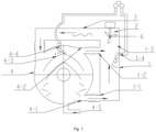
- Fig. 2 is another expression of the principle of a dual condensing system. As shown in the figure, the hot air blown by the electric heater enters the drum and can be simply divided into three parts: the first part passes through the air condensing duct 1 for condensation, the second part passes through the rear drum 4 for condensation, and the third part directly passes through the second air exhaust port 4-2 into the second air intake port 1-2. This is a drying cycle with low efficiency.
- the air condensing duct 1 is provided with a first air intake port 1-1, a second air intake port 1-2, and a third air exhaust port 1-3.
- the third air exhaust port 1-3 is located higher and connected to a fan volute assembly.
- the first air intake port 1-1 is located lower and far from the third air exhaust port 1-3.
- the condenser spray pipe 1-4 is located higher than the first air intake port 1-1. Steam enters the air condensing duct 1 via the first air intake port 1-1, and flows from the lower position to the higher position to be discharged from the air condensing duct 1 via the third air exhaust port 1-3.
- an external water source is sprayed in by the condenser spray pipe 1-4 to mix with the steam for condensation.
- the condensed water and the external water converge, pass through the first air intake port 1-1 and the first air exhaust port 4-1, and flow into the rear drum 4 to be discharged via the drainage port 4-5.
- the second air intake port 1-2 of the air condensing duct 1 is located higher than the first air intake port 1-1 and close to the third air exhaust port 1-3.
- Another part of the steam in the rear drum 4 exists between the inner wall of the outer drum of the washing machine and the outer wall of the inner drum of the washing machine, as shown in fig. 1 , between the bottom of the outer drum and the bottom of the inner drum.
- a rear drum spray pipe 4-4 and a water guide structure 4-3 are arranged according to a special rule.
- the water guide structure 4-3 is water guise ribs.
- the external water source is sprayed in by the rear drum spray pipe 4-4, and extends through a large water contact region created by the water guide structure 4-3 arranged according to a special rule to contact the steam for condensation.
- the condensed water and external water are discharged via the drainage port 4-5.
- this part of the air enters the air condensing duct 1 via the second air exhaust port 4-2 and the second air intake port 1-2.
- a small amount of uncondensed steam in this part of the air is condensed in the air condensing duct 1 with the help of external water introduced by the condenser spray pipe 1-4.
- the first air exhaust port 4-1 is located below the second air exhaust port 4-2, and the first air intake port 1-1 is located below the second air intake port 1-2.
- the first air exhaust port of this application is located at the lower, which can mainly guide out the hot and humid steam in the rear drum. Most of the steam has not undergone condensation and heat exchange in the rear drum and is humid.
- the second air exhaust port is located at the upper, which can mainly guide out the air, at the top of the rear drum, that has undergone condensation and heat exchange. This part of the air is mainly dehumidified dry air, and therefore located at the top.
- a rear wall of the rear drum 4 is vertically divided into three equal parts in a height direction, the first air exhaust port 4-1 is located within the lower third of the rear drum 4, and the second air exhaust port 4-2 is located within the upper third of the rear drum 4.
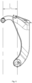
- Fig. 4 is a schematic structural diagram of a rear drum of a washing and drying machine with a dual condensing structure, showing a rear drum structure. Generally, the rear drum is divided into three equal parts. The second air exhaust port 4-2 is located in the upper third, and the first air exhaust port 4-1 is located in the lower third. This distribution is because a larger and longer condensation water contact area is needed to increase efficiency.
- a center line of the second air exhaust port 4-2 is perpendicular to a real drum wall of the rear drum.
- the center line of the second air exhaust port 4-2 is perpendicular to the rear drum wall. If it is parallel to the rear drum wall, condensed water from a pipeline between the second air exhaust port 4-2 and the second air intake port 1-2 is likely to drip onto the laundry, affecting drying. The condensed water from the second air exhaust port on the rear drum wall flows down along the inner wall of the rear drum, without wetting the laundry and affecting drying, thus improving the drying efficiency.
- a diameter ratio of the first air exhaust port 4-1 to the second air exhaust port 4-2 is 2/3-4.
- the optimal ratio of the aperture of the first air exhaust port 4-1 to the equivalent aperture of the second air exhaust port 4-2 is between 80/120 and 80/20. In some embodiments, the optimal ratio of the aperture of the first air exhaust port 4-1 to the equivalent aperture of the second air exhaust port 4-2 is 80/120. In some embodiments, the optimal ratio of the aperture of the first air exhaust port 4-1 to the equivalent aperture of the second air exhaust port 4-2 is 80/20.
- the diameter of the second air exhaust port 4-2 increases, that is, the ratio decreases, the amount of air passing through the third part increases, resulting in more ineffective or low-efficiency cycles, thus reducing drying efficiency.
- the diameter of the second air exhaust port 4-2 decreases, that is, the diameter ratio of the first air exhaust port 4-1 to the second air exhaust port 4-2 increases, the amount of air passing through the second part decreases, reducing the condensation efficiency of the rear drum, thus increasing drying time.
- the diameter ratio of the first air exhaust port 4-1 to the second air exhaust port 4-2 also affects the flow rate of the air passing through the second air exhaust port 4-2. If the diameter of the second air exhaust port 4-2 decreases, the flow rate is too large.
- the water flowing out of the rear drum spray pipe 4-4 or even the condenser spray pipe 1-4 is easily drawn back into the fan and rear-end pipeline and heated electrically to be sprayed back into the drum, reducing temperature, increasing humidity, and wetting the laundry again.
- the diameter of the second air exhaust port 4-2 cannot be too large; otherwise ineffective heat exchange increases. It should be neither too small; otherwise the condensation effect of the rear drum is poor. Therefore, choosing the range of 2/3-4 can ensure condensation and heat exchange of the rear drum while preventing or reducing ineffective heat exchange.
- a length from a center of the first air exhaust port 4-1 to a center of the second air exhaust port 4-2 along a horizontal direction is L
- a diameter of the rear drum 4 is D
- L/D 0.15-0.35.
- the second air intake port 1-2 is consistent with the second air exhaust port 4-2
- the first air intake port 1-1 is consistent with the first air exhaust port 4-1.
- the horizontal length distance between two lines, passing through the centers of the second air intake port 1-2 and the first air intake port 1-1, perpendicular to the ground is L in the fig. 5 , and a ratio of L to the diameter of the drum being 0.15-0.35 is preferable.
- the inner wall of the rear drum is provided with a plurality of water guide structures 4-3, a bottom of the rear drum 4 is provided with a drainage port 4-5, and a part of the rear drum spray pipe 4-4 is penetrated from an outside of the rear drum 4 to an inner side of the inner wall of the rear drum, so as to spray water onto the inner wall of the rear drum.
- the rear drum spray pipe of this application sprays water onto the inner wall of the rear drum, allowing the hot and humid air to complete heat exchange on the inner wall of the rear drum, achieving dehumidifying and cooling, and effectively avoiding situations such as directly spraying water into the rear drum and wetting the clothes. This also increases the heat exchange area, improving heat exchange efficiency.
- the rear drum spray pipe 4-4 introduces an external water source, and the water guide structure 4-3 arranged according to a special rule expands the water contact area.
- the second air exhaust port 4-2, the second air intake port 1-2, the air exhaust port 1-3, and the fan volute assembly serves as air path and the power source, facilitating the formation of the condenser extending portion.
- the entire machine space is used properly without increasing the overall cost, the condensation path is extended, the heat exchange phase change area is increased, the circulation airflow amount is increased, the drying efficiency is improved, the time is shortened, and electricity is saved.
- the laundry treatment apparatus when the air condensing duct 1 is further provided with the third air exhaust port 1-3, the laundry treatment apparatus further includes an air heating duct 3 and a heater 5, one end of the air heating duct 3 is provided with an air intake port 2, the air intake port 2 is communicated with the third air exhaust port 1-3 on the air condensing duct 1, another end of the air heating duct 3 is configured to communicate with the inner drum and/or the rear drum, and the heater 5 is disposed in the air heating duct 3.
- a fan 6 is disposed in the air heating duct 3; and/or the laundry treatment apparatus is a washing and drying machine.
Landscapes
- Engineering & Computer Science (AREA)
- Textile Engineering (AREA)
- Detail Structures Of Washing Machines And Dryers (AREA)
Applications Claiming Priority (2)
| Application Number | Priority Date | Filing Date | Title |
|---|---|---|---|
| CN202210467728.XA CN114775215B (zh) | 2022-04-29 | 2022-04-29 | 一种衣物处理装置 |
| PCT/CN2022/140856 WO2023207156A1 (zh) | 2022-04-29 | 2022-12-22 | 一种衣物处理装置 |
Publications (2)
| Publication Number | Publication Date |
|---|---|
| EP4516979A1 true EP4516979A1 (de) | 2025-03-05 |
| EP4516979A4 EP4516979A4 (de) | 2025-07-02 |
Family
ID=82434592
Family Applications (1)
| Application Number | Title | Priority Date | Filing Date |
|---|---|---|---|
| EP22939965.4A Pending EP4516979A4 (de) | 2022-04-29 | 2022-12-22 | Wäschebehandlungsvorrichtung |
Country Status (3)
| Country | Link |
|---|---|
| EP (1) | EP4516979A4 (de) |
| CN (1) | CN114775215B (de) |
| WO (1) | WO2023207156A1 (de) |
Families Citing this family (8)
| Publication number | Priority date | Publication date | Assignee | Title |
|---|---|---|---|---|
| CN114775215B (zh) * | 2022-04-29 | 2025-11-21 | 珠海格力电器股份有限公司 | 一种衣物处理装置 |
| CN115679608A (zh) * | 2022-10-27 | 2023-02-03 | 海信冰箱有限公司 | 洗干一体机 |
| CN117684375B (zh) * | 2023-11-16 | 2025-10-28 | 珠海格力电器股份有限公司 | 一种衣物处理设备 |
| CN117684371B (zh) * | 2023-11-16 | 2025-09-23 | 珠海格力电器股份有限公司 | 一种外筒组件、衣物处理设备及烘干控制方法 |
| CN117684344B (zh) * | 2023-11-16 | 2025-09-23 | 珠海格力电器股份有限公司 | 烘干系统、衣物烘干方法及衣物处理设备 |
| CN117684345B (zh) * | 2023-11-16 | 2025-09-23 | 珠海格力电器股份有限公司 | 一种衣物处理设备 |
| CN117684370B (zh) * | 2023-11-16 | 2025-10-28 | 珠海格力电器股份有限公司 | 一种外筒组件及衣物处理设备 |
| CN117569060B (zh) * | 2023-11-16 | 2026-01-20 | 珠海格力电器股份有限公司 | 一种衣物处理设备的冷凝结构、烘干风道及衣物处理设备 |
Family Cites Families (18)
| Publication number | Priority date | Publication date | Assignee | Title |
|---|---|---|---|---|
| JPH06277394A (ja) * | 1993-03-29 | 1994-10-04 | Matsushita Electric Ind Co Ltd | 衣類乾燥機 |
| TW593829B (en) * | 2001-05-23 | 2004-06-21 | Hitachi Ltd | Washing and drying machine and water-cooled heat exchanger |
| JP2003117283A (ja) * | 2001-10-17 | 2003-04-22 | Toshiba Corp | 洗濯乾燥機 |
| JP4444016B2 (ja) * | 2004-06-17 | 2010-03-31 | パナソニック株式会社 | 衣類乾燥装置 |
| KR100631574B1 (ko) * | 2005-08-13 | 2006-10-09 | 엘지전자 주식회사 | 응축식 세탁건조기 |
| KR101336705B1 (ko) * | 2007-01-30 | 2013-12-04 | 엘지전자 주식회사 | 세탁건조기 |
| CN102071563B (zh) * | 2009-11-25 | 2014-03-26 | 博西华电器(江苏)有限公司 | 衣物烘干设备 |
| JP2013081640A (ja) * | 2011-10-11 | 2013-05-09 | Panasonic Corp | 衣類乾燥機 |
| CN102691198A (zh) * | 2012-06-14 | 2012-09-26 | 惠而浦(中国)投资有限公司 | 洗衣烘干一体机的冷凝装置及冷凝方法 |
| KR20180019385A (ko) * | 2016-08-16 | 2018-02-26 | 엘지전자 주식회사 | 의류처리장치 |
| JP6862168B2 (ja) * | 2016-12-14 | 2021-04-21 | 日立グローバルライフソリューションズ株式会社 | 洗濯乾燥機 |
| CN106854825B (zh) * | 2017-02-06 | 2019-04-16 | 无锡小天鹅股份有限公司 | 干衣机及其控制方法 |
| CN108951051B (zh) * | 2017-05-25 | 2024-03-22 | 松下家电(中国)有限公司 | 一种滚筒洗干一体机 |
| CN109267286B (zh) * | 2018-11-02 | 2020-10-27 | 海信(山东)冰箱有限公司 | 一种烘干洗衣机 |
| CN112831985A (zh) * | 2019-11-22 | 2021-05-25 | 海信(山东)冰箱有限公司 | 一种洗衣机 |
| CN114045650B (zh) * | 2021-11-16 | 2022-08-26 | 珠海格力电器股份有限公司 | 一种延流结构、冷凝装置及洗干机 |
| CN114775215B (zh) * | 2022-04-29 | 2025-11-21 | 珠海格力电器股份有限公司 | 一种衣物处理装置 |
| CN217351852U (zh) * | 2022-04-29 | 2022-09-02 | 珠海格力电器股份有限公司 | 一种衣物处理装置 |
-
2022
- 2022-04-29 CN CN202210467728.XA patent/CN114775215B/zh active Active
- 2022-12-22 WO PCT/CN2022/140856 patent/WO2023207156A1/zh not_active Ceased
- 2022-12-22 EP EP22939965.4A patent/EP4516979A4/de active Pending
Also Published As
| Publication number | Publication date |
|---|---|
| WO2023207156A1 (zh) | 2023-11-02 |
| CN114775215A (zh) | 2022-07-22 |
| EP4516979A4 (de) | 2025-07-02 |
| CN114775215B (zh) | 2025-11-21 |
Similar Documents
| Publication | Publication Date | Title |
|---|---|---|
| EP4516979A1 (de) | Wäschebehandlungsvorrichtung | |
| CN117265845B (zh) | 一种衣物处理设备及衣物处理设备的烘干控制方法 | |
| CN104711833B (zh) | 干衣机 | |
| CN112127112A (zh) | 洗衣机筒体结构以及具有其的洗衣机 | |
| CN101349287B (zh) | 一种风机及洗干一体机 | |
| JP2002239284A (ja) | パルセーター方式の乾燥洗濯機 | |
| CN217351852U (zh) | 一种衣物处理装置 | |
| KR100379437B1 (ko) | 건조 세탁기 | |
| CN217479803U (zh) | 一种除湿器及衣物处理设备 | |
| CN117947619A (zh) | 一种冷凝风道及洗烘一体机 | |
| JP7466004B2 (ja) | 乾燥機器用の凝縮器及び乾燥機器 | |
| CN111005193B (zh) | 安装座及衣物处理装置 | |
| CN117684344B (zh) | 烘干系统、衣物烘干方法及衣物处理设备 | |
| CN209537875U (zh) | 一种干衣机导风结构及具有该导风结构的干衣机 | |
| CN114753089B (zh) | 一种衣物处理装置 | |
| CN115897186A (zh) | 烘干设备的烘干系统及烘干设备 | |
| WO2023010767A1 (zh) | 冷凝器及具有其的衣物处理设备 | |
| CN114775250A (zh) | 衣物处理装置冷凝组件和洗干机 | |
| CN111088676B (zh) | 基座及衣物处理装置 | |
| CN221142213U (zh) | 一种冷凝装置、烘干组件和智慧滚筒式洗衣机 | |
| KR100487760B1 (ko) | 의류건조기의 냉각공기 흡입구조 | |
| CN219568412U (zh) | 烘干设备的烘干系统及烘干设备 | |
| CN223983864U (zh) | 带干衣功能的衣物处理设备 | |
| CN119736781B (zh) | 一种衣物处理设备及控制方法 | |
| CN223329581U (zh) | 衣物处理设备 |
Legal Events
| Date | Code | Title | Description |
|---|---|---|---|
| STAA | Information on the status of an ep patent application or granted ep patent |
Free format text: STATUS: THE INTERNATIONAL PUBLICATION HAS BEEN MADE |
|
| PUAI | Public reference made under article 153(3) epc to a published international application that has entered the european phase |
Free format text: ORIGINAL CODE: 0009012 |
|
| STAA | Information on the status of an ep patent application or granted ep patent |
Free format text: STATUS: REQUEST FOR EXAMINATION WAS MADE |
|
| 17P | Request for examination filed |
Effective date: 20241126 |
|
| AK | Designated contracting states |
Kind code of ref document: A1 Designated state(s): AL AT BE BG CH CY CZ DE DK EE ES FI FR GB GR HR HU IE IS IT LI LT LU LV MC ME MK MT NL NO PL PT RO RS SE SI SK SM TR |
|
| REG | Reference to a national code |
Ref country code: DE Ref legal event code: R079 Free format text: PREVIOUS MAIN CLASS: D06F0025000000 Ipc: D06F0058240000 |
|
| A4 | Supplementary search report drawn up and despatched |
Effective date: 20250603 |
|
| RIC1 | Information provided on ipc code assigned before grant |
Ipc: D06F 25/00 20060101ALN20250528BHEP Ipc: D06F 58/02 20060101ALN20250528BHEP Ipc: D06F 58/24 20060101AFI20250528BHEP |
|
| DAV | Request for validation of the european patent (deleted) | ||
| DAX | Request for extension of the european patent (deleted) |