EP4516995A1 - Procédé de commande de vide dans une section de formage et section de formage avec un système de commande pour commander le vide de la section de formage - Google Patents
Procédé de commande de vide dans une section de formage et section de formage avec un système de commande pour commander le vide de la section de formage Download PDFInfo
- Publication number
- EP4516995A1 EP4516995A1 EP24187025.2A EP24187025A EP4516995A1 EP 4516995 A1 EP4516995 A1 EP 4516995A1 EP 24187025 A EP24187025 A EP 24187025A EP 4516995 A1 EP4516995 A1 EP 4516995A1
- Authority
- EP
- European Patent Office
- Prior art keywords
- vacuum
- wire
- forming
- dewatering
- set point
- Prior art date
- Legal status (The legal status is an assumption and is not a legal conclusion. Google has not performed a legal analysis and makes no representation as to the accuracy of the status listed.)
- Pending
Links
Images


Classifications
-
- D—TEXTILES; PAPER
- D21—PAPER-MAKING; PRODUCTION OF CELLULOSE
- D21F—PAPER-MAKING MACHINES; METHODS OF PRODUCING PAPER THEREON
- D21F1/00—Wet end of machines for making continuous webs of paper
- D21F1/48—Suction apparatus
-
- D—TEXTILES; PAPER
- D21—PAPER-MAKING; PRODUCTION OF CELLULOSE
- D21F—PAPER-MAKING MACHINES; METHODS OF PRODUCING PAPER THEREON
- D21F1/00—Wet end of machines for making continuous webs of paper
- D21F1/48—Suction apparatus
- D21F1/52—Suction boxes without rolls
-
- D—TEXTILES; PAPER
- D21—PAPER-MAKING; PRODUCTION OF CELLULOSE
- D21F—PAPER-MAKING MACHINES; METHODS OF PRODUCING PAPER THEREON
- D21F1/00—Wet end of machines for making continuous webs of paper
- D21F1/48—Suction apparatus
- D21F1/52—Suction boxes without rolls
- D21F1/523—Covers thereof
- D21F1/526—Covers thereof consisting of endless moving belts
-
- D—TEXTILES; PAPER
- D21—PAPER-MAKING; PRODUCTION OF CELLULOSE
- D21F—PAPER-MAKING MACHINES; METHODS OF PRODUCING PAPER THEREON
- D21F3/00—Press section of machines for making continuous webs of paper
- D21F3/02—Wet presses
- D21F3/10—Suction rolls, e.g. couch rolls
-
- D—TEXTILES; PAPER
- D21—PAPER-MAKING; PRODUCTION OF CELLULOSE
- D21F—PAPER-MAKING MACHINES; METHODS OF PRODUCING PAPER THEREON
- D21F7/00—Other details of machines for making continuous webs of paper
-
- D—TEXTILES; PAPER
- D21—PAPER-MAKING; PRODUCTION OF CELLULOSE
- D21F—PAPER-MAKING MACHINES; METHODS OF PRODUCING PAPER THEREON
- D21F9/00—Complete machines for making continuous webs of paper
- D21F9/003—Complete machines for making continuous webs of paper of the twin-wire type
-
- D—TEXTILES; PAPER
- D21—PAPER-MAKING; PRODUCTION OF CELLULOSE
- D21G—CALENDERS; ACCESSORIES FOR PAPER-MAKING MACHINES
- D21G9/00—Other accessories for paper-making machines
- D21G9/0009—Paper-making control systems
- D21G9/0027—Paper-making control systems controlling the forming section
Definitions
- the invention relates generally to producing fiber webs. Particularly the invention relates to a method for controlling vacuum in a forming section according to the preamble of the independent method claim and to a forming section with a control system for controlling vacuum of the forming section according to the preamble of the independent forming section claim.
- a typical production and treatment line comprise a forming section comprising a headbox and a forming unit and a press section as well as a subsequent drying section and a reel-up.
- the production and treatment line can further comprise other devices and sections for finishing the fiber web, for example, a size press, a calender, a coating section.
- the production and treatment line also comprise typically at least one winder for forming customer rolls as well as a roll packaging apparatus.
- the task of the headbox is to supply fiber suspension for the fiber web production into the forming unit.
- more than one fiber suspension flows are discharged from the headbox via flow channels for stock suspension layers, each for forming one layer of a multiply fiber web.
- the task of a forming unit is to remove water from fiber suspension fed by the headbox.
- water in the stock is removed on the forming section through a forming wire or forming wires for starting the formation of the web. Fibers remain on the forming wire or between the forming wires moving together.
- different types of stocks are used.
- the volume for which water can be removed from different stocks for achieving a web of good quality is a function of many factors, such as e.g. a function of the desired basis weight of the web, the design speed of the machine, and the desired level of fines, fibers and fill materials in the finished product.
- forming shoes such as forming shoes, foil boxes, suction boxes, turning rolls, suction rolls, and rolls provided with an open surface, which have been used in many different arrangements and arrays when trying to optimize the volume, time and location of water being removed when forming the fiber web.
- the manufacturing a high-quality end-product of desired grade is a function of the volume of dewatering, the dewatering method, the duration of dewatering, and the location of dewatering.
- Fiber webs especially paper and board are available in a wide variety of types and can be divided according to basis weight in two product grades: papers with a single ply and a basis weight of 25-300 g/m 2 and boards manufactured in single or multiply technology and having a basis weight of 80-600 m/m 2 .
- the borderline between paper and board is flexible since board product grades with lightest basis weights are lighter than the heaviest paper product grades.
- paper is used for printing and board for packaging.
- the stock suspensions to be used for producing different product grades of fiber webs vary in respect of the fiber web grade to be produced but typically at least certain drainage level is to be achieved in the forming section in order to form a fiber web suitable to be treated in a press section of a fiber web production line and to further remove water by pressing the fiber web in the press section.
- virgin or recycled fibers are refined to very fine fibers i.e. to highly refined stocks for the required stock suspension.
- Some product grades may also have high fines content.
- the highly refined stock and high fines content decrease dewatering properties of the stock suspension, for example a web sealing effect of the fiber web is possible and thus limitations on dewatering in the forming unit might be caused.
- each of suction boxes, such as vacuum foil boxes, of a fourdrinier wire, i.e. one-wire part have has its own automatic control valve for controlling its vacuum, in controlling of which set points values are set either manually or following a fiber web grade dependent table of set point values.
- each vacuum foil box also requires its own control circuit with its set point values. This makes the control system for controlling vacuum in the forming section complicated. Also, this needs multiple selection and setting of the set point values. Thus, the control system is cumbersome in its structure as well as in operation.
- the vacuum on the fourdrinier part i.e. on the one-wire part
- Amount of the water removal varies due to variations of the forming process in machine direction, which has an effect on joining consistency and other quality factors, such as scar-like markings, diagonal worm-shaped defects and seagull wing -shaped defects.
- the water removal of the vacuum forming shoe is to be detected at short intervals and thus, also vacuum control requires continuous setting ups and thus, takes up time.
- a forming section in a machine for producing a web of fibrous material comprising: at least one continuous rotating wire supporting a fibrous stock suspension at least indirectly; a compression zone; a plurality of dewatering units, at least two of said plurality of dewatering units being one of located in series and respectively located following each other in a direction of travel of said fibrous stock suspension inside said compression zone; and a control and/or regulating system including: a control and/or regulating device; at least one device for at least indirectly acquiring a value at least indirectly characterizing a dry content of the web in a transfer area from the forming section to a following function unit, said control and/or regulating device being linked with at least one said device for at least indirectly acquiring said value at least indirectly characterizing said dry content of the web in said transfer area from the forming section to said following function unit; a device for input of a desired value for a target dry content, said control and/or regulating device being linked with said
- a vacuum dual control system for the flat box section of a papermaking machine comprising: a plurality of serially arranged vacuum boxes; a header interconnecting said boxes; a vacuum pump operatively connected to said boxes in a manner so that the vacuum applied to the boxes is a function of the speed of the pump; a first control means for operating the pump at an initial substantially constant high speed to produce the vacuum necessary to dewater a web in its initial condition; means for passing the web to be dewatered over the boxes so that suction applied therethrough by the pump running at its initial substantially constant high speed dewaters the web until the condition of the web changes sufficiently to cause the vacuum in the last box to increase to a predetermined maximum level; a second control means having set point adjustment means thereon to enable selection of a predetermined set point corresponding to the predetermined maximum vacuum level, said second control means being connected to the last box and the vacuum pump and including sensing means to sense the predetermined maximum vacuum level as determined by the second control means predetermined maximum vacuum level as determined by
- An object of the invention is to create a method for controlling vacuum in a forming section, in which the disadvantages and problems of prior art are eliminated or at least minimized.
- An object of the invention is to create a forming section with a control system for controlling vacuum of the forming section, in which the disadvantages and problems of prior art are eliminated or at least minimized.
- An object of the invention is to create a method for controlling vacuum in a forming section and a forming section with a control system for controlling vacuum of the forming section, in which disadvantages and problems in controlling of vacuum in forming sections known from prior art are eliminated or at least minimized.
- the method according to the invention is mainly characterized by the features of the characterizing clause of the independent method claim and the forming section according to the invention is mainly characterized by the features of the characterizing clause of the independent forming section claim.
- vacuum of at the fourdrinier wire of the forming section is automatically controlled on basis of dewatering amount of an upper wire part of a twin-wire part following the fourdrinier wire part, advantageously on basis of dewatering data information received from at least one vacuum forming shoe located in the upper wire part of a twin-wire part following the fourdrinier wire part.
- the vacuum at the fourdrinier wire can be controlled on basis of measurement data received from a measuring device in the fiber web production line, for example on basis of layer thickness measurement.
- vacuums of successive suction boxes are to be scaled increasing, advantageously uniformly increasing.
- the equation for calculating a vacuum of a suction box in an arrangement of several, successive suction boxes is P i ⁇ P i+1 and the set point value of the vacuum of the last suction box in the arrangement of several, successive suction boxes is set independently on basis of a measurement result of dewatering, for example manually.
- a minimum vacuum is set for the first of the suction boxes after the head-box and a maximum vacuum is set for the last of the suction boxes of the successive arrangement of the suction boxes and when the vacuum of the last suction box changes, the vacuum of the previous suction boxes is calculated based on the equation P i ⁇ P i+1 .
- the set point value may be defined on basis of information in a stored data collection of set point values for different fiber web product grades.
- the control system when controlling vacuum in the forming section with a fourdrinier wire and with a vacuum forming shoe, is provided with an intelligent add-on configured to detect amount of the dewatering at the vacuum forming shoe and control vacuum at the fourdrinier wire to keep the dewatering at the fourdrinier wire at the desired level (dead band).
- the vacuum at the fourdrinier wire is controlled by controlling vacuum of water removal devices located at the fourdrinier wire.
- the vacuum at the fourdrinier wire part is controlled by controlling the main vacuum such, that desired water removal at following upper wire part is achieved, i.e. by controlling water removal by controlling the vacuum at the fourdrinier wire part the upper wire part has enough water to be removed. This provides a steady, non-operator-related control of the vacuum and thus, production quality variations are decreased, and good, stabile level of quality is achieved.
- the control system when controlling vacuum in the forming section with a fourdrinier wire and with a vacuum forming shoe, is provided with an intelligent add-on configured to detect amount of the dewatering at the vacuum forming shoe and control set point value of the main vacuum at the fourdrinier wire to fix amount of dewatering at the vacuum forming shoe to a selected range by controlling set point value of the main vacuum at the fourdrinier wire.
- an operator sets a set point value of the dewatering amount in a time interval (for example l/s) and the control provides that the amount in a time interval of the dewatering is kept at the set range (for example 10 l/s).
- the forming section comprises an arrangement of several, successive suction boxes at the fourdrinier wire and the vacuum there of is controlled.
- the set point value of the vacuum of the last of the several, successive suction boxes at the fourdrinier wire is set on basis of the detected amount of the dewatering at the vacuum forming shoe.
- control system comprises at least one controller comprising at least a processor and a memory and a computer code for example a software application, to provide control instructions on basis of dewatering amount of an upper wire part of a twin-wire part following the fourdrinier wire part, advantageously on basis of dewatering data information received from at least one vacuum forming shoe located in the upper wire part of a twin-wire part following the fourdrinier wire part.
- the controller of the control system receives, collects, processes, stores and transmits data.
- the control system and the controller may be configured as one entity, or it may be configured of separate units connected with each other by means of data transfer connections.
- the control system and the controller are configured to provide control data to control vacuum in the forming section.
- the control data is transmitted to control the vacuum in the forming section.
- the control data may be transmitted to a control unit of an element and/or of a device and/or of a section of the fiber web production line.
- the controller may be configured to provide automatic control and/or to manual control of the vacuum of the forming section.
- control and its derivates
- control is meant to control at least one element and/or at least one device operationally connected to the forming section.
- the controller of the control system advantageously comprises at least one processor and at least one memory including computer program code, the at least one memory and the computer program code are configured, with the at least one processor, to generate and transmit signals as first control data to the forming section based on first information data received from the forming section, and based on second information data received the fiber web production line and/or based on third data received automatically and/or manually as input value/-s from a data storage.
- the method of controlling vacuum of the forming section advantageously comprises receiving first, and second and/or third information data, processing the received first, and second and/or third information data according to predetermined configuration, based on the processed data, generating signals according to predetermined configuration to control the vacuum of the forming section.
- the method and the forming section according to the invention provide for optimal, uniformly increasing vacuum profile in the arrangement of several, successive suction boxes at the fourdrinier wire only by changing the set point value of the last of the several, successive suction boxes in the arrangement.
- the invention also provides that the manual operations in controlling the vacuum in the forming section is minimized and thus, human errors by operators are decreased, as vacuum circuits of individual suction boxes of the arrangement of the several, successive suction boxes do not need to be set individually manually.
- the invention provides that desired, increasing vacuum profile is automatically controlled at the fourdrinier wire and thus, improved quality and runnability is achieved, for example more even distribution of fines is provided.
- Solution according to invention decreases fiber web machine energy consumption, increases forming section ceramics and fabrics lifetime and optimized fiber web properties. By this way is possible to dewater the fiber web so that web is not compacted too early. It improves glue penetration in the sizer and decreases vacuum need in the forming section.
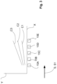
- FIGS 1-2 is shown advantageous examples of a forming section 200 with a vacuum control system for advantageous examples of a method for controlling vacuum in a forming section.
- Each forming section 200 comprises at least one head box M1, M2 for feeding stock suspension to a forming unit 250.
- the forming section 200 comprises a control system 100 for controlling vacuum in the forming unit 250 of the forming section 200.
- FIG 1 is shown an example in connection with production of a single layer fiber web W or in connection with production of a multilayer fiber web with multilayer W headbox.
- figure 2 is shown an example in connection with production of a two-layer fiber web W.
- FIG 1 in addition to the forming section 200 also beginning of a press section 300 following the forming section 200 is shown.
- FIG 1 an example of a forming section 200 for producing a single layer fiber web W with single layer headbox M1 or a multilayer fiber web W with multilayer headbox M1.
- Running direction is indicated by an arrow S.
- the forming section 200 in this example comprises the one headbox M1 and a forming unit 250, also beginning of a press section 300 is shown.
- the forming section 200 is thus for production of a fiber web W, which can contain one or more fiber web layers.
- the forming section 200 comprises a headbox M1, from which the stock suspension is fed to the forming unit 250 beginning as single-wire part with substantially horizontal run i.e.
- a fourdrinier part comprising a first wire 10 for single-wire runs and a second wire 20 for twin-wire runs for forming the fiber web W.
- first wire 10 for single-wire runs to the headbox M1 only one stock suspension is fed, but in case in which multilayer fiber web W is manufactured, to the headbox M1 is fed two or more equivalent or different kind of stock suspensions.
- Stock suspensions can differ from each other based on raw material, fiber length, fiber freeness or additives difference.
- Each wire 10, 20 comprises rolls 12, 22 for guiding, tensioning and/or driving the first and the second wire 10, 20 as endless first and second wire loops 10, 20.
- the stock suspension from the headbox M1 is first fed onto a single-wire run of a first wire 10, i.e.
- the stock on the fourdrinier wire 10 is guided past inside the loop of the first wire 10 at the beginning run thereof located water removal means 11A-11C, which can be for example foil boxes and/or suction devices, and then past the loop of the first wire 10 located suction boxes 15A-15E with controllable vacuum.
- water removal means 11A-11C can be for example foil boxes and/or suction devices, and then past the loop of the first wire 10 located suction boxes 15A-15E with controllable vacuum.
- the fiber web water removal is substantially horizontal.
- the first one-wire run is followed by a twin-wire run, during which the fiber web is running between the two wires 10, 20 of a twin-wire part of the forming unit 250.
- twin-wire run water is removed by controllable water removal means 16A-16C, advantageously controllable vacuum forming shoes 16A-16B having optional adjustable loading blades P in the opposite, first wire loop 10.
- the twin-wire run is followed by another single-wire run, on which run further water removal means 14A, 14B are located, which can also function as support means for supporting the run of the fiber web W.
- the fiber web W is guided via inside the first fire loop 10 located suction roll 13 of the forming unit 250 towards a pick-up roll 41 for transferring the fiber web to a first press fabric 40 of the press section 300.
- the press section also comprises a second press fabric 50 with a roll 51.
- the press fabrics 40, 50 comprise rolls 42, 52 for guiding, tensioning and/or driving the fabrics 40; 50 as an endless loop.
- the fiber web W is guided between the first press fabric 40 and the second press fabric 50 to a press nip formed between a first press roll 45 and a second press roll 55.
- control system 100 for controlling vacuum in the forming section 200 comprises a controller 150 connected operationally to several, successive suction boxes 15A-15E with controllable vacuum at the first wire 10, i.e. at the fourdrinier wire 10.
- Each of the successive suction boxes 15A-15B comprises a control element V5A-V5E, for example an adjustable valve V5A-V5E, to control vacuum of the corresponding suction box 15A-15B.
- a vacuum set point value of the last suction box 15E is set independently and the set point values of preceding suction boxes 15A-15D is calculated from the set point value of the following suction box 15B-15E such, that the set point value of the vacuum P i of a suction box 15A-15B is smaller than the set point value of the vacuum P i+1 of the following suction box 15B-15E, where i indicated the order of the suction box and is 1, 2, 3, 4,..., where 1 is the location of the first suction box 15A-15E in the running direction S or in the example i is indicated by signs A, B, C,...
- the equation for calculating the vacuum of a suction box 15A-15D in an arrangement of several, successive suction boxes 15A-15E is P i ⁇ P i+1 and the set point value of the vacuum of the last suction box 15E in the arrangement of several, successive suction boxes 15A-15E is set independently, on basis of a calculated set point value, which is calculated for example on basis of a measurement result of dewatering.
- the set point value of the vacuum may be defined together on basis of information in a stored data collection of set point values for different fiber web product grades.
- vacuum of each of the several, successive suction boxes 15A-15E at the fourdrinier wire 10 is automatically controlled on basis of data information received from a measurement device of the fiber web production line, for example on basis of layer thickness measurement, and/or on basis of dewatering data information received from the forming unit 250, for example from at least one vacuum forming shoe 16A-16C located at the second wire 20, i.e. the upper wire 20 in the upper wire part of the twin-wire part following the fourdrinier wire part.
- the control system 100 may also be provided with an intelligent add-on 110 configured to detect amount of the dewatering at the vacuum forming shoe/-s 1A-16C and control vacuum at the fourdrinier wire 10 to keep the dewatering at the fourdrinier wire 10 at the desired level (dead band).
- the vacuum at the fourdrinier wire 10 is controlled by controlling vacuum of at least one of water removal devices 11A-11C, 15A-15E, preferably vacuum of the successive suction boxes 15A-15E, located at the fourdrinier wire 10.
- an operator sets a set point value of the dewatering amount of the first top suction unit suction box 16A of the successive suction boxes 16A-16C in a time interval (for example l/s) and the control provides that the amount in a time interval of the dewatering is kept at the set range (for example 10 l/s).
- an operator can set a set point value of the dewatering amount of the last suction box 15E of the successive suction boxes 15A-15E in a time interval (for example l/s) and the control provides that the amount in a time interval of the dewatering is kept at the set range (for example 10 l/s).
- FIG 2 an example of a forming section 200 for producing a multilayer fiber web W with at least two layers is shown.
- Running direction of forming of first layer/-s W1 is denoted by an arrow S1 and running direction of forming of second layer/-s W2 and combined layers W1, W2 is denoted by an arrow S2.
- the forming section is provided with two headboxes M1, M2, one or both of which can be single layer headboxes M1, M2 or multilayer headboxes M1, M2.
- the forming section 200 in this example comprises the two headboxes M1 and a forming unit 250.
- the forming section 200 is for production of a multilayer fiber web W, which can contain two or more fiber web layers W1, W2.
- the forming section 200 comprises one headbox M1, from which the stock suspension is fed to the forming unit 250 for forming of a first layer/-s of the fiber web W.
- the forming unit 250 begins as single-wire part with substantially horizontal run i.e. a fourdrinier part comprising a first wire 10 for single-wire runs and a second wire 20 for twin-wire runs for forming the fiber web W.
- the first layer/-s comprises only single layer
- to the headbox M1 only one stock suspension is fed, but in case in which the first layer/-s of the multilayer fiber web W comprises more than one layers to the headbox M1 is fed two or more equivalent or different kind of stock suspensions.
- Stock suspensions can differ from each other based on raw material, fiber length, fiber freeness or additives difference.
- Each wire 10, 20 comprises rolls 12, 22 for guiding, tensioning and/or driving the wire 10; 20 as an endless loop.
- the stock suspension from the headbox M1 is first fed onto a single-wire run of a first wire 10, i.e. onto the fourdrinier wire 10 and thereafter the stock/-s on the fourdrinier wire 10 is guided past inside the loop of the first wire 10 at the beginning run thereof located water removal means 11A-11C, which can be for example foil boxes and/or suction devices, and then past the loop of the first wire 10 located suction boxes 15A-15E with controllable vacuum.
- water removal means 11A-11C which can be for example foil boxes and/or suction devices, and then past the loop of the first wire 10 located suction boxes 15A-15E with controllable vacuum.
- the fiber web water removal is substantially horizontal.
- control system 100 for controlling vacuum in the forming section 200 comprises a controller 150 connected operationally to several, successive suction boxes 15A-15E with controllable vacuum at the first wire 10, i.e. at the fourdrinier wire 10.
- Each of the successive suction boxes 15A-15B comprises a control element V5A-V5E, for example an adjustable valve V5A-V5E, to control vacuum of the corresponding suction box 15A-15B.
- a vacuum set point value of the last suction box 15E is set independently and the set point values of preceding suction boxes 15A-15D is calculated from the set point value of the following suction box 15B-15E such, that the set point value of the vacuum P i of a suction box 15A-15B is smaller than the set point value of the vacuum P i+1 of the following suction box 15B-15E, where i indicated the order of the suction box and is 1, 2, 3, 4,..., where 1 is the location of the first suction box 15A-15E in the running direction S1 or in the example i is indicated by signs A, B, C,...
- the equation for calculating the vacuum of a suction box 15A-15D in an arrangement of several, successive suction boxes 15A-15E is P i ⁇ P i+1 and the set point value of the vacuum of the last suction box 15E in the arrangement of several, successive suction boxes 15A-15E is set independently, for example manually, on basis of a measurement result of dewatering. Additionally the set point value can be calculated on basis of information in a stored data collection of set point values for different fiber web product grades.
- vacuum of each of the several, successive suction boxes 15A-15E at the fourdrinier wire 10 is automatically controlled on basis of data information received from a measurement device of the fiber web production line, for example on basis of layer thickness measurement, and/or on basis of dewatering data information received from the forming unit 250, for example from at least one vacuum forming shoe 16A-16C located at the second wire 20, i.e. the upper wire 20 of of the twin-wire 10, 20 part following the fourdrinier wire 10 part.
- the control system 100 may also be provided with an intelligent add-on 110 configured to detect amount of the dewatering at the vacuum forming shoe/-s 16A-16C and control vacuum at the fourdrinier wire 10 to keep the dewatering at the fourdrinier wire 10 at the desired level (dead band).
- the vacuum at the fourdrinier wire 10 is controlled by controlling vacuum of at least one of water removal devices 11A-11C, 15A-15E, preferably vacuum of the successive suction boxes 15A-15E, located at the fourdrinier wire 10.
- an operator sets a set point value of the dewatering amount of the first top suction unit suction box 16A of the successive suction boxes 16A-16C in a time interval (for example l/s) and the control provides that the amount in a time interval of the dewatering is kept at the set range (for example 10 l/s).
- an operator can set a set point value of the dewatering amount of the last suction box 15E of the successive suction boxes 15A-15E in a time interval (for example l/s) and the control provides that the amount in a time interval of the dewatering is kept at the set range (for example 10 l/s).
- control system 100 comprises at least one controller 150 comprising at least a processor and a memory and a computer code for example a software application, to provide control instructions based on measurement results of dewatering amount of an upper wire 20 part of a twin-wire 10, 20 part following the fourdrinier wire 10 part, advantageously on basis of dewatering data information received from at least one vacuum forming shoe 16A-16C located in the upper wire 20 part of a twin-wire 10, 20 part following the fourdrinier wire 20 part.
- the controller 150 of the control system 100 receives, collects, processes, stores and transmits data.
- the control system 100 and the controller 150 may be configured as one entity or it may be configured of separate units connected with each other by means of data transfer connections.
- the control system 100 and the controller 150 is configured to provide control data to control vacuum in the forming section.
- the control data is transmitted to control the vacuum in the forming section 200.
- the control data may be transmitted to a control unit of an element and/or of a device and/or of a section of the fiber web production line.
- the controller 150 may be configured to provide automatic control and/or to manual control of the vacuum of the forming section 200.
- the controller 150 of the control system 100 advantageously comprises at least one processor and at least one memory including computer program code, the at least one memory and the computer program code are configured, with the at least one processor, to generate and transmit signals as first control data to the forming section 200 based on first information data received from the forming section 200, and based on second information data received the fiber web production line and/or based on third data received automatically and/or manually as input value/-s from a data storage.
- the method of controlling vacuum of the forming section 200 advantageously comprises: receiving first, and second and/or third information data, processing the received first, and second and/or third information data according to predetermined configuration, based on the processed data, generating signals according to predetermined configuration to control the vacuum of the forming section 200.
- the set point value of the last can be selected for example on basis of layer thickness measurement or by dewatering amount in connection with an upper wire of the twin wire part following the fourdrinier wire part.
- the vacuum set point value of the last suction box 15E has been increased at selected intervals, for example at 2 kPa steps, in a vacuum value range, for example 0-16 kPa with coefficient a value of 0,7.
Landscapes
- Paper (AREA)
- Processing And Handling Of Plastics And Other Materials For Molding In General (AREA)
- Drying Of Solid Materials (AREA)
Applications Claiming Priority (1)
| Application Number | Priority Date | Filing Date | Title |
|---|---|---|---|
| FI20235950A FI131544B1 (en) | 2023-08-28 | 2023-08-28 | Method for regulating negative pressure in a forming section and forming section with a control system for regulating the negative pressure of the forming section |
Publications (1)
| Publication Number | Publication Date |
|---|---|
| EP4516995A1 true EP4516995A1 (fr) | 2025-03-05 |
Family
ID=91856209
Family Applications (1)
| Application Number | Title | Priority Date | Filing Date |
|---|---|---|---|
| EP24187025.2A Pending EP4516995A1 (fr) | 2023-08-28 | 2024-07-08 | Procédé de commande de vide dans une section de formage et section de formage avec un système de commande pour commander le vide de la section de formage |
Country Status (3)
| Country | Link |
|---|---|
| EP (1) | EP4516995A1 (fr) |
| CN (1) | CN119531165A (fr) |
| FI (1) | FI131544B1 (fr) |
Citations (4)
| Publication number | Priority date | Publication date | Assignee | Title |
|---|---|---|---|---|
| US4466873A (en) | 1981-06-19 | 1984-08-21 | Albany International Corp. | Vacuum dual control system for the flat box section of a papermaking machine |
| US20020096301A1 (en) * | 2001-01-22 | 2002-07-25 | Michael Odell | Twin-wire former |
| WO2005068715A1 (fr) * | 2003-12-22 | 2005-07-28 | Astenjohnson, Inc. | Dispositif de formation de type hybride pour machine a fabriquer le papier |
| US20120145346A1 (en) | 2008-07-24 | 2012-06-14 | Voith Patent Gmbh | Method for optimizing the energy balance in forming sections in machines for the production of fibrous webs, and forming section |
-
2023
- 2023-08-28 FI FI20235950A patent/FI131544B1/en active
-
2024
- 2024-07-08 EP EP24187025.2A patent/EP4516995A1/fr active Pending
- 2024-08-14 CN CN202411115414.9A patent/CN119531165A/zh active Pending
Patent Citations (4)
| Publication number | Priority date | Publication date | Assignee | Title |
|---|---|---|---|---|
| US4466873A (en) | 1981-06-19 | 1984-08-21 | Albany International Corp. | Vacuum dual control system for the flat box section of a papermaking machine |
| US20020096301A1 (en) * | 2001-01-22 | 2002-07-25 | Michael Odell | Twin-wire former |
| WO2005068715A1 (fr) * | 2003-12-22 | 2005-07-28 | Astenjohnson, Inc. | Dispositif de formation de type hybride pour machine a fabriquer le papier |
| US20120145346A1 (en) | 2008-07-24 | 2012-06-14 | Voith Patent Gmbh | Method for optimizing the energy balance in forming sections in machines for the production of fibrous webs, and forming section |
Also Published As
| Publication number | Publication date |
|---|---|
| CN119531165A (zh) | 2025-02-28 |
| FI20235950A1 (en) | 2025-03-01 |
| FI131544B1 (en) | 2025-06-17 |
Similar Documents
| Publication | Publication Date | Title |
|---|---|---|
| CA1313965C (fr) | Methode et dispositif pour l'obtention d'une bobine de papier multicouche | |
| US20080115902A1 (en) | Forming of a Paper or Board Web in a Twin-Wire Former or in a Twin-Wire Section of a Former | |
| CN111041892B (zh) | 多层片纤维幅材的施胶方法及多层片纤维幅材的成形部 | |
| JPH0377317B2 (fr) | ||
| US8323452B2 (en) | Method for optimizing the energy balance in forming sections in machines for the production of fibrous webs, and forming section using control elements associated with dewatering units | |
| US6375799B1 (en) | Process and apparatus for producing a fibrous material web | |
| CN108691235B (zh) | 多叠纤维幅材的成形部段和多叠纤维幅材的成形方法 | |
| EP4516995A1 (fr) | Procédé de commande de vide dans une section de formage et section de formage avec un système de commande pour commander le vide de la section de formage | |
| EP4516994A1 (fr) | Procédé de commande de vide dans une section de formage et section de formage avec un système de commande pour commander le vide dans la section de formage | |
| US20090165973A1 (en) | Web-Forming Section and Method for Manufacturing Multi-Layer Web | |
| US11512431B2 (en) | Method of forming a three-layer board web and a forming section of forming a three-layer board web | |
| FI111173B (fi) | Menetelmä paperirainan laadun hallitsemiseksi | |
| JP2004533562A (ja) | 紙若しくは板紙のサイズ処理されるウェブを製造する方法及び装置 | |
| WO2000031336A1 (fr) | Dispositif et procede pour secher la pate a papier | |
| EP0233058B1 (fr) | Procédé et appareil pour la fabrication d'un carton multicouche | |
| EP4006230A1 (fr) | Procédé de formation d'une bande de matière fibreuse et section de formation pour la formation d'une bande de matière fibreuse | |
| EP4636157A1 (fr) | Procédé de formation d'une bande de carton multicouche et section de formation pour former une bande de carton multicouche, et chaîne de production de bande de fibres pour produire des bandes de carton multicouche | |
| EP4663847A1 (fr) | Procédé de formation d'une bande de fibres et section de formation pour former une bande de fibres | |
| FI129446B (en) | Forming portion of a fibrous web production line | |
| FI20227069A1 (en) | Fiber web machine for producing a multilayer fiber web | |
| Misra | Developments in Forming and Pressing of Paper Web | |
| Kruska et al. | Advanced Paper Machine Concepts for the Production of Packaging Papers |
Legal Events
| Date | Code | Title | Description |
|---|---|---|---|
| PUAI | Public reference made under article 153(3) epc to a published international application that has entered the european phase |
Free format text: ORIGINAL CODE: 0009012 |
|
| STAA | Information on the status of an ep patent application or granted ep patent |
Free format text: STATUS: THE APPLICATION HAS BEEN PUBLISHED |
|
| AK | Designated contracting states |
Kind code of ref document: A1 Designated state(s): AL AT BE BG CH CY CZ DE DK EE ES FI FR GB GR HR HU IE IS IT LI LT LU LV MC ME MK MT NL NO PL PT RO RS SE SI SK SM TR |
|
| STAA | Information on the status of an ep patent application or granted ep patent |
Free format text: STATUS: REQUEST FOR EXAMINATION WAS MADE |
|
| 17P | Request for examination filed |
Effective date: 20250826 |