EP4517009A1 - Arbeitsmaschinensteuerungsverfahren, arbeitsmaschinensteuerungsprogramm, arbeitsmaschinensteuerungssystem und arbeitsmaschine - Google Patents
Arbeitsmaschinensteuerungsverfahren, arbeitsmaschinensteuerungsprogramm, arbeitsmaschinensteuerungssystem und arbeitsmaschine Download PDFInfo
- Publication number
- EP4517009A1 EP4517009A1 EP23194903.3A EP23194903A EP4517009A1 EP 4517009 A1 EP4517009 A1 EP 4517009A1 EP 23194903 A EP23194903 A EP 23194903A EP 4517009 A1 EP4517009 A1 EP 4517009A1
- Authority
- EP
- European Patent Office
- Prior art keywords
- work machine
- state
- unit
- display
- control method
- Prior art date
- Legal status (The legal status is an assumption and is not a legal conclusion. Google has not performed a legal analysis and makes no representation as to the accuracy of the status listed.)
- Pending
Links
Images



Classifications
-
- E—FIXED CONSTRUCTIONS
- E02—HYDRAULIC ENGINEERING; FOUNDATIONS; SOIL SHIFTING
- E02F—DREDGING; SOIL-SHIFTING
- E02F9/00—Component parts of dredgers or soil-shifting machines, not restricted to one of the kinds covered by groups E02F3/00 - E02F7/00
- E02F9/24—Safety devices, e.g. for preventing overload
-
- E—FIXED CONSTRUCTIONS
- E02—HYDRAULIC ENGINEERING; FOUNDATIONS; SOIL SHIFTING
- E02F—DREDGING; SOIL-SHIFTING
- E02F9/00—Component parts of dredgers or soil-shifting machines, not restricted to one of the kinds covered by groups E02F3/00 - E02F7/00
- E02F9/20—Drives; Control devices
- E02F9/2004—Control mechanisms, e.g. control levers
Definitions
- the present invention relates to a work machine control method, a work machine control program, and a work machine control system that are used for a work machine having a function of detecting a detection target in a surrounding monitoring area, and to a work machine.
- a work machine capable of suppressing erroneous actuation of a work unit (an attachment)
- the work machine has: an actuator that is driven by an operation device that is installed in a cab mounted on an upper turning body; and a controller capable of restricting motion of the actuator.
- the controller uses a detector to determine whether the operation device is operated by an operator's hand, and restricts the motion of the actuator when the operation device is not operated by the operator's hand.
- the detector is a camera that captures an image of the operator who is seated on a driver's seat, and captures an image of a monitoring area that corresponds to a movable range of the operation device so as to be able to determine whether the operation device such as an operation lever is operated by the operator's hand.
- Patent Document 1 WO2019/039522
- An object of the present invention is to provide a work machine control method, a work machine control program, a work machine control system, and a work machine capable of improving operability.
- a work machine control method has: shifting a state of a work machine from an inoperable state to an operable state on the basis of an unlock operation of an unlock operation unit.
- the work machine control method further has: shifting the state of the work machine from the operable state to the inoperable state when a specific condition including a condition that a specific operation unit related to an operation of the work machine remains unoperated for a standby time after the unlock operation is satisfied.
- a work machine control program is a program for causing one or more processors to execute the work machine control method.
- a work machine control system includes an unlock processing unit and further includes a lock processing unit.
- the unlock processing unit shifts the state of the work machine from the inoperable state to the operable state on the basis of the unlock operation of the unlock operation unit.
- the lock processing unit shifts the state of the work machine from the operable state to the inoperable state when a specific condition including a condition that a specific operation unit related to an operation of the work machine remains unoperated for a standby time after the unlock operation is satisfied.
- a work machine includes the work machine control system and a machine body.
- the work machine control method, the work machine control program, the work machine control system, and the work machine each of which easily improves operability, can be provided.
- a work machine 3 includes a travel unit 31, a turning unit 32, and a work unit 33.
- the work machine 3 also includes a driving unit 34 which an occupant can get in.
- the driving unit 34 includes a driver's seat and the like.
- the driver's seat is a seat on which the occupant is seated.
- the travel unit 31, the turning unit 32, the work unit 33, and the driving unit 34 are included in a machine body 30 of the work machine 3.
- the work machine 3 further includes a work machine control system 1 (hereinafter also simply referred to as a "control system 1") and an operation device 2.
- the machine body 30 includes a display device, various sensors (including a sonar, a camera, and the like), and the like.
- the "work machine” described in the present disclosure means a machine for any of various types of work, and examples thereof are work vehicles such as a backhoe (including a hydraulic excavator, a mini excavator, and the like), a wheel loader, and a carrier.
- the work machine 3 includes the work unit 33 configured to be able to perform one or more types of work.
- the work machine 3 is not limited to the "vehicle” and may be a work vessel, a flying work body such as a drone or a multi-copter, or the like, for example.
- the work machine 3 is not limited to a construction machine (construction equipment) and may be an agricultural machine (agricultural equipment) such as a rice trans-planter, a tractor, or a combine harvester, for example.
- an agricultural machine agricultural equipment
- a description will be made on, as an example, a case where the work machine 3 is a riding-type backhoe and can perform excavation work, land leveling work, trenching work, loading work, or the like as the work.
- the work machine 3 is of an "ultra-small turning type" in which the turning unit 32 including the work unit 33 can make a full turn within 120% of an overall width of the travel unit 31 (an overall width of a right and left pair of crawlers 311) or of a "rear ultra-small turning type” in which a rear end turning radius ratio is within 120%.
- the occupant who gets in the driving unit 34 is an operator, and the work machine 3 is run by the operator's operation.
- the present invention is not limited to this example.
- the work machine 3 may be runnable by a remote operation or automated driving.
- the plural occupants may be able to get in the driving unit 34 simultaneously.
- the plural driver's seats may be provided in the single driving unit 34.
- a vertical direction in a usable state of the work machine 3 will be defined as an up-down direction D1 for convenience of description.
- a front-rear direction D2 and a right-left direction D3 will be defined with directions seen from the operator, who gets in the driving unit 34 of the work machine 3, being a reference.
- each of the directions used in the present embodiment is a direction that is defined with the driving unit 34 of the work machine 3 being the reference.
- a movement direction of the machine body 30 during forward travel of the work machine 3 will be defined as "front”
- a movement direction of the machine body 30 during reverse travel of the work machine 3 will be defined as "rear”.
- a direction in which a front end portion of the machine body 30 moves during a right turn of the work machine 3 will be defined as "right”
- a direction in which the front end portion of the machine body 30 moves during a left turn of the work machine 3 will be defined as "left”.
- the driving unit 34 is provided to the turning unit 32, the front-rear direction D2 and the right-left direction D3 with respect to the travel unit 31 are changed with turning of the turning unit 32.
- the directions will hereinafter be defined on the basis of a state where a front portion of the driving unit 34 faces an advancing direction of the travel unit 31.
- these directions are not intended to limit a use direction (a direction in use) of the work machine 3.
- the work machine 3 includes an engine as a power source.
- the engine is a diesel engine.
- the engine is driven by fuel (herein, diesel fuel) that is supplied from a fuel tank.
- the engine drives a hydraulic pump 41 (see FIG. 3 ), and hydraulic oil is supplied from the hydraulic pump 41 to hydraulic actuators (including a hydraulic motor 61, a hydraulic cylinder 62, and the like) in components of the machine body 30.
- hydraulic actuators including a hydraulic motor 61, a hydraulic cylinder 62, and the like
- Such a work machine 3 is controlled, for example, when the operator who gets in the driving unit 34 of the machine body 30 operates operation levers 21, 22 (see FIG. 4 ) of the operation device 2, or the like.
- the work machine 3 is assumed to be the riding-type backhoe.
- the work unit 33 is driven through the operation by the operator who gets in the driving unit 34, and performs the work such as the excavation work.
- the work unit 33 is supported on the turning unit 32 that is provided with the driving unit 34.
- the turning unit 32 turns, the work unit 33 turns with the driving unit 34.
- the operation device 2, the display device, and the like are mounted in the driving unit 34 of the machine body 30.
- the operator can operate the operation device 2 while looking at various types of information on the work machine 3 that are displayed on the display device.
- information on a running condition of the work machine 3 such as a coolant temperature and a hydraulic oil temperature, is displayed on a display screen of the display device. Accordingly, the operator can check the information on the running condition of the work machine 3, which is required to operate the operation device 2, on the display device.
- the travel unit 31 has a travel function and is configured to be able to travel (also turn) on the ground.
- the travel unit 31 has the right and left pair of crawlers 311 and a blade 312, for example.
- the travel unit 31 further has the traveling hydraulic motor 61 (the hydraulic actuator) for driving the crawlers 311, and the like.
- the turning unit 32 is arranged above the travel unit 31 and can turn with respect to the travel unit 31 in plan view.
- the turning unit 32 is located above the travel unit 31 and is configured to be turnable about a rotation axis along the vertical direction with respect to the travel unit 31.
- the turning unit 32 has a hydraulic motor as a turning hydraulic actuator, and the like.
- the driving unit 34 the engine, the hydraulic pump, and the like are mounted on the turning unit 32.
- the turning unit 32 is provided with a boom bracket, to which the work unit 33 is attached.
- the turning unit 32 has a substantially circular shape with a front end portion being cut flat. The turning unit 32 can turn about a center of the circular shape as the rotation axis.
- the work unit 33 is supported by the turning unit 32 and is configured to be able to perform one or more types of the work.
- the work unit 33 is supported by the boom bracket in the turning unit 32 and performs the work.
- the work unit 33 has a bucket 331.
- the bucket 331 is a type of an attachment (a work tool) that is attached to the machine body 30 of the work machine 3, and is an appropriate tool that is selected from plural types of the attachments according to a work content.
- the bucket 331 is detachably attached to the machine body 30 and is replaced according to the work content.
- Examples of the (end) attachment for the work machine 3 are, in addition to the bucket 331, various tools such as a breaker, an auger, a crusher, a fork, a fork claw, a steel cutter, an asphalt cutter, a mower, a ripper, a mulcher, a tilt rotator, and a tamper.
- various tools such as a breaker, an auger, a crusher, a fork, a fork claw, a steel cutter, an asphalt cutter, a mower, a ripper, a mulcher, a tilt rotator, and a tamper.
- the work unit 33 further has a boom 332, an arm 333, the hydraulic actuators (including the hydraulic cylinder 62, a hydraulic motor, and the like), and the like.
- the bucket 331 is attached to a tip of the arm 333.
- the bucket 331 is supported by the arm 333 in a rotatable manner about a rotation axis along a horizontal direction.
- the boom 332 is rotatably supported by the boom bracket of the turning unit 32. More specifically, the boom 332 is supported by the boom bracket in a rotatable manner about the rotation axis along the horizontal direction.
- the boom 332 has a shape that extends upward from a base end portion supported by the boom bracket.
- the arm 333 is coupled to a tip of the boom 332.
- the arm 333 is supported by the boom 332 in a rotatable manner about the rotation axis along the horizontal direction.
- the work unit 33 is powered by the engine as the power source. More specifically, the hydraulic pump 41 is driven by the engine and supplies the hydraulic oil to the hydraulic actuators (the hydraulic cylinder 62 and the like) of the work unit 33, and the components (the bucket 331, the boom 332, and the arm 333) of the work unit 33 are thereby run.
- the hydraulic pump 41 is driven by the engine and supplies the hydraulic oil to the hydraulic actuators (the hydraulic cylinder 62 and the like) of the work unit 33, and the components (the bucket 331, the boom 332, and the arm 333) of the work unit 33 are thereby run.
- the work unit 33 has a multi-joint structure in which the boom 332 and the arm 333 are configured to be separately rotatable.
- each of the boom 332 and the arm 333 rotates about the rotation axis along the horizontal axis.
- the multi-joint work unit 33 which includes the boom 332 and the arm 333, can make extending motion and folding motion as a whole, for example.
- the bucket 331 as the attachment is supported by the machine body 30 (the turning unit 32) via the boom 332 and the arm 333, and can be opened/closed when the bucket 331 itself rotates with respect to the arm 333.
- each of the travel unit 31 and the turning unit 32 is also powered by the engine as the power source.
- the hydraulic oil is supplied from the hydraulic pump 41 to the hydraulic motor 61 of the travel unit 31, the hydraulic motor of the turning unit 32, and the like, and the turning unit 32 and the travel unit 31 are thereby run.
- the work machine 3 further includes a drive device (mechanism) such as a power take-off (PTO) for supplying the power to the bucket 331 (the attachment). More specifically, the drive device delivers the hydraulic oil from the hydraulic pump 41, which is driven by the engine, to the bucket 331, and regulates a flow rate of the hydraulic oil, so as to regulate an amount of the power supplied to the bucket 331.
- a drive device such as a power take-off (PTO) for supplying the power to the bucket 331 (the attachment). More specifically, the drive device delivers the hydraulic oil from the hydraulic pump 41, which is driven by the engine, to the bucket 331, and regulates a flow rate of the hydraulic oil, so as to regulate an amount of the power supplied to the bucket 331.
- the driving unit 34 is a space for the operator to get in.
- the driving unit 34 is located on the turning unit 32. Accordingly, when the turning unit 32 turns in the plan view, the driving unit 34 turns together. More specifically, in the case where the turning unit 32 is divided into two in the right-left direction D3, the driving unit 34 is provided on a left portion thereof.
- the driving unit 34 at least has the driver's seat on which the operator is seated.
- the driving unit 34 of the work machine 3, which is the construction machine or the like, is of a cabin type, a canopy type, a floor type, or the like.
- the driving unit 34 of the cabin type has a cabin 341, and the operator gets in a cabin space inside the cabin 341.
- the driving unit 34 of the canopy type includes a canopy (a roof), and the operator gets in a space under the canopy.
- the driving unit 34 of the floor type does not include the cabin 341, the canopy, and the like, and the operator gets in a space that is opened upward. That is, the driving unit 34 includes not only a mode of being surrounded by panels or the like but also various modes of the space prepared for the operator to get in. In the present embodiment, a description will be made on a case where the driving unit 34 is of the cabin type as an example.
- the driving unit 34 is located above the left crawler 311 (see FIG. 1 ). With such arrangement, the operator gets in/out of the driving unit 34 from a left side of the driving unit 34. Accordingly, in the present embodiment, a door 342 for the driving unit 34 is arranged on the left side in the right-left direction D3 of the driving unit 34. That is, the operator walks through the door 342, which is arranged on the left side of the driving unit 34, to get in the driving unit 34 or get out of the driving unit 34 therethrough.
- the driving unit 34 of the cabin type includes the cabin 341 in a shape of covering the driver's seat.
- the cabin 341 constitutes a contour of the driving unit 34, and the operator gets in (inside) the cabin 341. With the door 342, the cabin 341 surrounds four sides of the cabin space.
- the operation device 2 is arranged in the driving unit 34 and is a user interface that accepts an operation input by the operator. As illustrated in FIG. 3 , in the present embodiment, as an example, the operation device 2 includes a right and left pair of the operation levers 21, 22, and the like. The operation levers 21, 22 of the operation device 2 are located on both sides in the right-left direction D3 of a front end portion of the driver's seat. In this way, the operator who is seated on the driver's seat can operate the operation device 2 without a significant change in his/her posture.
- an unlock operation unit 20 and a display 35 are provided to each of the paired the operation levers 21, 22.
- the unlock operation unit 20 is connected to the control system 1 and outputs, to the control system 1, an operation signal that corresponds to an operation of the unlock operation unit 20.
- the display 35 is connected to the control system 1, and changes a display state when being controlled by the control system 1. A detailed description on the configuration of the operation device 2 will be made in the section of "[2] Operation Device".
- the display device is arranged in the driving unit 34 and is a user interface that outputs the various types of the information to the operator.
- the display device is controlled by the control system 1 and displays various screens to present (output) the various types of the information.
- the display device may have a sound (including voice) output function in addition to the display function, and may present the various types of the information by sound.
- the display device includes an input unit such as a touchscreen, and accepts any of various types of operations by the operator by outputting an electric signal that corresponds to the operator's operation. As a result, the operator can visually check the display screen that is displayed on the display device, and can operate the display device when necessary.
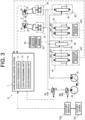
- FIG. 3 schematically illustrates a hydraulic circuit and an electric circuit (an electrical connection relationship) of the work machine 3 according to the present embodiment.
- a solid line represents a high-pressure oil path (for the hydraulic oil)
- a dotted line represents a low-pressure oil path (for pilot oil)
- a one-dot chain arrow represents an electric signal path.
- a bold (solid) line between a cutoff lever 521 and a cutoff switch 522 represents a physical connection between the cutoff lever 521 and the cutoff switch 522.
- the work machine 3 includes, in addition to the control system 1 and the hydraulic pump 41, a pilot pump 42, a first hydraulic circuit 43, a second hydraulic circuit 44, a third hydraulic circuit 45, an inlet valve 46, and remote control valves 47, 48.
- the work machine 3 further includes a first control valve 51, a second control valve 52, the cutoff lever 521, the cutoff switch 522, and the like.
- the hydraulic oil from the hydraulic pump 41 which is driven by the engine, is supplied to the hydraulic motor 61 of the travel unit 31, the hydraulic motor of the turning unit 32, the hydraulic cylinder 62 of the work unit 33, and the like. In this way, the (hydraulic) actuators such as the hydraulic motor 61 and the hydraulic cylinder 62 are driven.
- the first hydraulic circuit 43 includes plural first direction switching valves (control valves) 431 of a pilot type, each of which can switch a direction and the flow rate of the hydraulic oil from the hydraulic pump 41.
- Each of the plural first direction switching valves 431 is provided in a manner to correspond to the actuator (the hydraulic cylinder 62 or the like) of the work unit 33, and is driven when being supplied with a pilot signal (the pilot oil) as an input command from the pilot pump 42.
- the remote control valves 47, 48 are provided to pilot signal supply paths to these plural first direction switching valves 431.
- each of the plural first direction switching valves 431 is driven by a secondary pressure of respective one of the remote control valves 47, 48, and the corresponding actuator (the hydraulic cylinder 62 or the like) of the work unit 33 is thereby driven.
- each of the remote control valves 47, 48 outputs a work operation command to the work unit 33 according to the operation of the operation device 2 (the operation levers 21, 22), thereby drives the actuators of the work unit 33, and causes the work unit 33 to make expansion motion, contraction motion, or the like.
- the second hydraulic circuit 44 includes plural second direction switching valves 441 of the pilot type, each of which can switch the direction and the flow rate of the hydraulic oil from the hydraulic pump 41.
- Each of the plural second direction switching valves 441 is provided in a manner to correspond to the actuator (the hydraulic motor 61 or the like) of the travel unit 31, and is driven when being supplied with the pilot signal as the input command from the pilot pump 42.
- a remote control valve is provided to a pilot signal supply path to these plural second direction switching valves 441. The remote control valve works cooperatively with the operation device 2 such as an unillustrated travel lever.
- each of the plural second direction switching valves 441 is driven by a secondary pressure of the remote control valve that works cooperatively with the travel lever, and the corresponding actuator (the hydraulic motor 61 or the like) of the travel unit 31 is thereby driven.
- the remote control valve outputs a travel operation command to the travel unit 31 according to the operation of the operation device 2 (the travel lever), thereby drives the actuators of the travel unit 31, and causes the travel unit 31 to make travel motion (travel forward, travel reversely, or the like).
- the third hydraulic circuit 45 includes a third direction switching valve 451 of the pilot type capable of switching the direction and the flow rate of the hydraulic oil from the hydraulic pump 41.
- the third direction switching valve 451 is provided in a manner to correspond to the actuator (the hydraulic motor) of the turning unit 32, and is driven when being supplied with the pilot signal as the input command from the pilot pump 42.
- the remote control valve 47 is provided to a pilot signal supply path to the third direction switching valve 451.
- the third direction switching valve 451 is driven by the secondary pressure of the remote control valve 47, and the corresponding actuator (the hydraulic motor) of the turning unit 32 is thereby driven.
- the remote control valve 47 outputs a turning operation command to the turning unit 32 according to the operation of the operation device 2 (the operation lever 21), thereby drives the actuator of the turning unit 32, and causes the turning unit 32 to make turning motion (a left turn, a right turn, or the like).
- a turning brake 64 is attached to the hydraulic motor (a turning motor 63) that is the actuator of the turning unit 32.
- the turning brake 64 locks the turning motor 63 of the turning unit 32 by a spring force, so as to restrict the turning motion of the turning unit 32.
- the turning brake 64 is driven when being supplied with the pilot signal that is the input command from the pilot pump 42, and unlocks the turning motor 63 in a disrupted state of the pilot signal.
- the inlet valve 46 distributes the hydraulic oil from the hydraulic pump 41 to each of the first hydraulic circuit 43 and the second hydraulic circuit 44.
- the direction switching valves (the first direction switching valve 431 and the second direction switching valve 441) of the first hydraulic circuit 43 and the second hydraulic circuit 44 are driven.
- the corresponding actuators (the hydraulic cylinder 62 and the hydraulic motor 61) are driven.
- the inlet valve 46 is driven by the pilot signal that is the input command from the pilot pump 42, and switches a supply destination of the hydraulic oil from the hydraulic pump 41 among the first hydraulic circuit 43, the second hydraulic circuit 44, and the tank.
- the inlet valve 46 selects the first hydraulic circuit 43 and the second hydraulic circuit 44 as the supply destinations of the hydraulic oil from the hydraulic pump 41.
- the inlet valve 46 selects the tank as the supply destination of the hydraulic oil from the hydraulic pump 41.
- FIG. 3 illustrates the configuration that the hydraulic oil is supplied from the single hydraulic pump 41 to the first hydraulic circuit 43, the second hydraulic circuit 44, and the third hydraulic circuit 45.
- the invention is not limited thereto, and the hydraulic oil may be supplied from the separate hydraulic pumps 41. That is, for example, the hydraulic pump 41 as a supply source of the hydraulic oil may differ between the first hydraulic circuit 43 and the second hydraulic circuit 44, for example.
- the operation device 2 controls the remote control valves 47, 48 according to operation amounts of the operation levers 21, 22, and thereby controls the turning unit 32 and the work unit 33.
- the operation device 2 controls the remote control valve according to an operation amount of the travel lever, and thereby controls the travel unit 31. That is, the operator can actuate the remote control valves 47, 48 by operating the operation device 2 to instruct the direction and the flow rate of the hydraulic oil from the hydraulic pump 41, and can thereby run the work machine 3.
- the first hydraulic circuit 43 and the second hydraulic circuit 44 respectively have pressure sensors 432, 442.
- Each of the pressure sensors 432, 442 detects a pressure of the detection pilot signal (a pilot pressure) that is generated in a detection hydraulic circuit according to motion of a spool in respective one of the first direction switching valve 431 and the second direction switching valve 441.
- the pressure sensors 432, 442 are connected to the control system 1, and pressure detection signals indicative of the pressures detected by the pressure sensors 432, 442 are input to the control system 1.
- Actuation states of the remote control valves 47, 48 that is, operation states of the operation levers 21, 22 (the operation device 2) are reflected to the pressures detected by the pressure sensors 432, 442, respectively.
- each of the pressure sensors 432, 442 may be configured to detect the pressure that varies by the operation state of the operation device 2, and, for example, may directly detect the pressure of the pilot signal (the pilot pressure) of respective one of the first direction switching valve 431 and the second direction switching valve 441.
- the first control valve 51 is provided to the pilot signal supply path from the pilot pump 42 to the inlet valve 46 and the remote control valves 47, 48.
- the second control valve 52 is provided on an upstream side (the pilot pump 42 side) of the first control valve 51 in the pilot signal supply path from the pilot pump 42 to the inlet valve 46 and the remote control valves 47, 48.
- the first control valve 51 and the second control valve 52 that are inserted in series in the pilot signal path are electromagnetic control valves (electromagnetic valves). Accordingly, the pilot signal path to the inlet valve 46 and the remote control valves 47, 48 is opened only in a state where both of the first control valve 51 and the second control valve 52 are opened. In other words, the pilot signal path to the inlet valve 46 and the remote control valves 47, 48 is closed in a state where at least one of the first control valve 51 and the second control valve 52 is closed.
- the first control valve 51 is connected to the control system 1, is run according to a control signal (a supply current) from the control system 1, and switches opening/closing of the path for the pilot signal supplied from the pilot pump 42 to the inlet valve 46 and the remote control valves 47, 48. That is, in the opened state of the first control valve 51, the first control valve 51 is brought into an "unlocked state" where the path is opened. In the closed state of the first control valve 51, the first control valve 51 is brought into a "locked state” where the path is closed.
- a control signal a supply current
- the second control valve 52 is a cutoff valve, is connected to a power source via the cutoff switch 522, and is run according to the supply current from the power source.
- the second control valve 52 closes the pilot signal path.
- the second control valve 52 opens the pilot signal path.
- the cutoff switch 522 works cooperatively with the cutoff lever 521.
- the cutoff lever 521 is arranged in the driving unit 34 of the machine body 30 and accepts an operation input by the operator. In the present embodiment, as an example, the cutoff lever 521 can be operated along the up-down direction D1.
- the cutoff lever 521 is located at a "raised position” that is an upper end position in a movable range
- the cutoff switch 522 is "on”.
- the cutoff switch 522 is "off”. Then, the cutoff switch 522 is connected to the control system 1, and on/off of the cutoff switch 522 is monitored by the control system 1.
- the pilot signal to be supplied to the inlet valve 46 is cut off. Accordingly, since the hydraulic oil from the hydraulic pump 41 is no longer supplied to the first hydraulic circuit 43 and the second hydraulic circuit 44, at least the actuators of the travel unit 31 and the work unit 33 can no longer be driven, and then the travel unit 31 and the work unit 33 are forcibly stopped without the operation of the operation device 2. Furthermore, at this time, a primary pressure (the pilot signal) to the remote control valves 47, 48 is also cut off. Thus, even when the operation device 2 is operated, the remote control valves 47, 48 are not driven.
- the work machine 3 when at least one of the first control valve 51 and the second control valve 52 is in the locked state, the work machine 3 is brought into an "inoperable state" where at least the travel unit 31 and the work unit 33 cannot be operated. Meanwhile, when both of the first control valve 51 and the second control valve 52 are in the unlocked state, the work machine 3 is brought into an "operable state” where the travel unit 31, the turning unit 32, and the work unit 33 can be operated.
- the cutoff lever 521 is at the "raised position” and the cutoff switch 522 is on, running of the work machine 3 is forcibly restricted regardless of the operation of the operation device 2.
- the cutoff lever 521 is a lever that is operated to lock running of the work machine 3 as described above, and is synonymous with a gate lock lever.
- the first control valve 51 is a component of a first lock device 101
- the second control valve 52 is a component of a second lock device 102. That is, the work machine 3 according to the present embodiment includes the first lock device 101 and the second lock device 102, each of which can be switched between the locked state and the unlocked state.
- the first lock device 101 includes the first control valve 51
- the second lock device 102 includes the second control valve 52.
- the control system 1 is mainly configured as a computer system that has one or more processors such as a central processing unit (CPU) and one or more types of memory such as read only memory (ROM) and random access memory (RAM), and executes various types of processing (information processing).
- the control system 1 is an integrated controller that controls the entire work machine 3, and includes an electronic control unit (ECU), for example.
- ECU electronice control unit
- the control system 1 may be provided separately from the integrated controller. A detailed description on the control system will be made in the section of "[3] Configuration of Control System".
- the machine body 30 includes a communication terminal, the fuel tank, a battery, and the like.
- the machine body 30 further includes sensors for monitoring a running condition of the machine body 30, and examples of the sensors are a coolant temperature sensor, a hydraulic oil temperature sensor, a tachometer for measuring an engine speed, and an hour meter for measuring a running time.
- the operation device 2 has the pair of the operation levers 21, 22.
- the operation lever 21 is located on a left hand side when seen from the operator who gets in the driving unit 34
- the operation lever 22 is located on a right hand side when seen from the operator who gets in the driving unit 34. Accordingly, for example, by holding the operation lever 21 with the operator's left hand and holding the operation lever 22 with the operator's right hand, and by operating these paired operation levers 21, 22, the operator causes the work machine 3 to make any of various types of the motion such as the forward travel and the reverse travel.
- the operation device 2 has plural (four herein) operators Sw1 to Sw4.
- the operators Sw1 to Sw4 are arranged on a front surface side (a front side) of each of the operation levers 21, 22.
- each of the operators Sw1 to Sw3 is a momentary-type push-button switch.
- the operation element Sw4 is a lever switch operable to be tilted rightward or leftward.
- Each of the operation levers 21, 22 further has the unlock operation unit 20 and the display 35.
- the unlock operation unit 20 and the display 35 are arranged on the front surface side (the front side) of each of the operation levers 21, 22.
- the unlock operation unit 20 is an operation unit for shifting the state of the work machine 3 from the inoperable state to the operable state.
- the unlock operation unit 20 is a momentary-type push-button switch.
- the unlock operation unit 20 accepts an operation (an unlocking operation) by the operator when being pushed by the operator.
- a display state of the display 35 is changed depending on whether the state of the work machine 3 is the inoperable state or the operable state. For this reason, by looking at the display 35, the operator can comprehend whether the state of the work machine 3 is the inoperable state or the operable state.
- the display 35 includes light-emitting element such as an LED, and presents any of the various types of the information according to a light-emitting state (a lighting state) thereof.
- the display 35 is arranged at a position corresponding to the unlock operation unit 20. More specifically, the display 35 is provided near (an adjacent position to) the unlock operation unit 20 or integrally with the unlock operation unit 20. In the present embodiment, the display 35 is integrated with the unlock operation unit 20, and an operation surface of the unlock operation unit 20 has translucency. In this way, the display state of the display 35 can be checked visually. For this reason, the operator can easily operate the unlock operation unit 20 after comprehending whether the state of the work machine 3 is the inoperable state or the operable state.
- the control system 1 is the component of the work machine 3 and, together with the machine body 30 and the like, constitutes the work machine 3.
- the work machine 3 according to the present embodiment at least includes the control system 1 and the machine body 30 (including the travel unit 31, the turning unit 32, and the work unit 33).
- the control system 1 includes a display processing unit 11, a lock processing unit 12, and an unlock processing unit 13.
- the control system 1 is mainly configured as the computer system that has the one or more processors.
- these plural functional units are implemented.
- These plural functional units included in the control system 1 may separately be provided in plural casings or may be provided in a single casing.
- the control system 1 is configured to be communicable with the device that is provided to each of the units of the machine body 30. More specifically, at least the unlock operation unit 20, the display 35, the pressure sensors 432, 442, the cutoff switch 522, the first control valve 51, and the like are connected to the control system 1. In this way, the control system 1 can control the display 35, the first control valve 51, and the like, and can acquire the electric signals from the unlock operation unit 20, the pressure sensors 432, 442, the cutoff switch 522, and the like.
- the control system 1 may exchange the various types of the information (data) either directly with each of the devices or indirectly with each of the device via a repeater or the like.
- the display processing unit 11 controls the display 35 and thereby executes display processing to cause the display 35 to display.
- the display 35 serves as both of a first display and a second display.
- the first display displays whether the state of the work machine 3 is the inoperable state or the operable state.
- the second display displays whether the second lock device 102 is in the locked state or the unlocked state. That is, the display processing unit 11 changes the display state (the lighting state) of the display 35 as the first display depending on whether the work machine 3 is in the inoperable state or the operable state, and changes the display state (the lighting state) of the display 35 as the second display depending on whether the second lock device 102 is in the locked state or the unlocked state.
- the lock processing unit 12 executes first lock processing to switch the first lock device 101 from the unlocked state to the locked state. More specifically, the lock processing unit 12 closes the first control valve 51 of the first lock device 101 and thereby switches the first lock device 101 from the unlocked state to the locked state.
- the unlock processing unit 13 executes unlock processing for shifting the state of the work machine 3 from the inoperable state to the operable state on the basis of an unlock operation of the unlock operation unit 20. More specifically, the unlock processing unit 13 opens the first control valve 51 of the first lock device 101 on the basis of the unlock operation of the unlock operation unit 20 and thereby switches the first lock device 101 from the locked state to the unlocked state.
- the lock processing unit 12 executes shifting processing to shift the state of the work machine 3 from the operable state to the inoperable state. More specifically, when satisfying the specific condition after the unlock operation of the unlock operation unit 20, the lock processing unit 12 closes the first control valve 51 of the first lock device 101 and thereby shifts the first lock device 101 from the unlocked state to the locked state.
- the specific condition includes a condition that the specific operation unit related to the operation of the work machine 3 remains not operated for a standby time.
- the operation levers 21, 22 of the operation device 2 are an example of the specific operation unit.
- the standby time is set as a fixed time.
- the present invention is not limited thereto and may vary according to a peripheral condition.
- the standby time may vary by presence or absence or a state of the operator or a person around the work machine 3.
- the standby time is preferably extended.
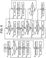
- control method for the work machine 3 (hereinafter, simply referred to as a "control method") that is mainly executed by the control system 1 with reference to FIG. 5 .
- control program The control method according to the present embodiment is executed by the control system 1 that is mainly configured as the computer system, and thus, in other words, is embodied by a work machine control program (hereinafter, simply referred to as a "control program"). That is, the control program according to the present embodiment is a computer program that causes the one or more processors to execute each of the processing related to the control method. For example, such a control program may cooperatively be executed by the control system 1 and the operation device 2.
- the control system 1 executes the following various types of the processing related to the control method.
- An example of the start operation is an operation to activate the engine of the work machine 3.
- a preset specific termination operation is performed, the control system 1 terminates the following various types of the processing related to the control method.
- An example of the termination operation is an operation to stop the engine of the work machine 3.
- step S1 onward processing in step S1 onward is started at a time point at which the operation to activate the engine of the work machine 3 (ignition on) is performed.
- step S1 the display processing unit 11 of the control system 1 continuously turns on the display 35 as the second display.
- the work machine 3 can perform the engine activation operation only in the state where the cutoff lever 521 is at the raised position. Accordingly, in step S1, inevitably, the cutoff lever 521 is at the raised position, and the second lock device 102 (the second control valve 52) is in the locked state. That is, at this time, since the second lock device 102 (the second control valve 52) is in the locked state, the display processing unit 11 continuously turns on the display 35.
- step S3 the second control valve 52 of the second lock device 102 remains in the locked state (a closed state) (S3). Furthermore, in step S4, the lock processing unit 12 brings the first control valve 51 of the first lock device 101 into the locked state (the closed state). That is, since both of the first lock device 101 and the second lock device 102 are in the locked state, the work machine 3 is brought into the inoperable state (S5), and the processing returns to step S2.
- step S2 if the cutoff lever 521 is operated to be located at the lowered position in step S2 (S2: Down), the second control valve 52 of the second lock device 102 is brought into the unlocked state (an open state) (S6). However, at the time, since the first control valve 51 of the first lock device 101 remains in the locked state (the closed state), the work machine 3 maintains the inoperable state (S5).
- next step S7 the display processing unit 11 blinks (intermittently turns on) the display 35 as the second display.
- the display processing unit 11 changes the display state of the display 35 from a continuously turned state to a blinked state. That is, the display processing unit 11 changes the display state of the second display (the display 35) depending on whether the second lock device 102 is in the locked state or the unlocked state. Accordingly, the operator can comprehend, from the display state of the second display (the display 35), that the second lock device 102 is brought into the unlocked state, that is, that the unlock operation can be accepted.
- step S8 if the unlock operation unit 20 is operated, the display processing unit 11 determines that the unlock operation has been performed (S8: Yes), and turns off the display 35 as the first display. That is, at this time, the unlock processing unit 13 brings the first control valve 51 of the first lock device 101 into the unlocked state (the open state) (S10). In this way, since both of the first lock device 101 and the second lock device 102 are in the unlocked state, the work machine 3 is brought into the operable state (S13).
- the display processing unit 11 changes the display state of the display 35 from the blinked state to a turned-off state when the state of the work machine 3 is switched from the inoperable state to the operable state. That is, the display processing unit 11 changes the display state of the first display (the display 35) depending on whether the state of the work machine 3 is the inoperable state or the operable state. In this way, the operator can comprehend, from the display state of the first display (the display 35), that the work machine 3 is brought into the operable state.
- the unlock processing unit 13 After bringing the first control valve 51 of the first lock device 101 into the unlocked state (the open state) (S10), the unlock processing unit 13 accepts the operations of the operation levers 21, 22 (S12) while starting a timer for the standby time (S 11). At this time, if at least one of the operation levers 21, 22 is operated (S12: Yes), the work machine 3 is run according to the operation due to a fact that the work machine 3 is in the operable state (S13). Thereafter, if both of the operation levers 21, 22 are no longer operated (S14: No), the timer for the standby time is reset (S15), and the processing returns to step S11.
- step S14 if at least one of the operation levers 21, 22 is operated in step S14 (S14: Yes), the unlock processing unit 13 brings the first control valve 51 of the first lock device 101 into the unlocked state (the open state) (S16), and the processing returns to step S13.
- the timer is ended (S17: Yes). Then, the display processing unit 11 blinks (intermittently turns on) the display 35 as the second display (S18), and the lock processing unit 12 brings the first control valve 51 of the first lock device 101 into the locked state (the closed state) (S19). In this way, since the first lock device 101 is in the locked state, the work machine 3 is brought into the inoperable state (S20).
- the lock processing unit 12 executes the shifting processing to shift the state of the work machine 3 from the operable state to the inoperable state (S20).
- the specific condition includes the condition that the specific operation unit related to the operation of the work machine 3 remains not operated for the standby time (S12: No and S17: Yes). Furthermore, at this time, the state of the work machine 3 is switched to the inoperable state, and the display processing unit 11 thereby changes the display state of the display 35 from the turned-off state to the blinked state (S18).
- step S8 if the unlock operation is not performed (S8: No), the processing proceeds to step S18, In this way, the inoperable state of the work machine 3 is continued (S20).
- the control system 1 repeatedly executes the processing in steps S2 to S20 described above.
- the flowchart illustrated in FIG. 5 is merely one example. Processing may appropriately be added or omitted, or an order of the processing may appropriately be switched.
- the control method has: shifting the state of the work machine 3 from the inoperable state to the operable state on the basis of the unlock operation by the unlock operation unit 20 (S13).
- This control method further has: when the specific condition is satisfied after the unlock operation (S8: Yes), shifting the state of the work machine 3 from the operable state to the inoperable state (S20).
- the specific condition includes the condition that the specific operation unit (the operation levers 21, 22) related to the operation of the work machine 3 remains not operated for the standby time (S12: No and S17: Yes).
- the work machine 3 is maintained in the inoperable state. In this way, it is possible to suppress the work machine 3 from being run by the operation of the operation device 2 that is not intended by the operator. In addition, even in the case where the unlock operation of the unlock operation unit 20 is performed, the work machine 3 returns to be in the inoperable state when the unoperated state of the operation device 2 continues for the standby time. Thus, it is possible to suppress the work machine 3 from being run by the operation of the operation device 2 that is not intended by the operator. As a result, there is an advantage of easily improving operability.
- the display state of the first display (the display 35) is changed depending on whether the state of the work machine 3 is the inoperable state or the operable state. Accordingly, when the operator is notified of whether the work machine 3 is in the inoperable state or the operable state, it is possible to suppress the work machine 3 from being run by the operation of the operation device 2 that is not intended by the operator while suppressing the operability from being reduced for a reason that the operator does not notice the inoperable state.
- the unlock operation unit 20 is provided to the specific operation unit.
- the unlock operation unit 20 is provided to the specific operation unit (the operation levers 21, 22) included in the specific condition, the operator can intuitively perform the unlock operation at the time of exhibiting the intention to operate the specific operation unit.
- the work machine 3 includes: the first lock device 101 that is switched from the locked state to the unlocked state on the basis of the unlock operation; and the second lock device 102 that can be switched between the locked state and the unlocked state separately from the first lock device 101.
- the work machine 3 is brought into the operable state. In this way, the operation of the work machine 3 is doubly restricted by the first lock device 101 and the second lock device 102.
- the unlock operation can be accepted (S8).
- the unlock operation is unacceptable.
- the display state of the second display (the display 35) is changed. More specifically, in the present embodiment, the display processing unit 11 changes the display state of the second display (the display 35) from the turned-off state to the continuously blinked state in accordance with the activation of the engine (S1). In this way, in the work machine 3 in which the activation operation of the power source can be performed only when the second lock device 102 is in the locked state, the operator can be notified of the locked state of the second lock device 102 after the activation of the power source. Thus, it is possible to suppress the reduced operability, which is caused when the operator does not notice the inoperable state.
- the actuators are controlled by the secondary pressures that are output from the remote control valves 47, 48 using the pilot signal as the primary pressure. Accordingly, since the pilot signal is blocked by the first control valve 51, the remote control valves 47, 48 are disabled. In addition, since the operation of the operation device 2 itself can be disabled, it is possible to further reliably suppress the work machine 3 from being run by the operation of the operation device 2 that is not intended by the operator.
- the second lock device 102 includes the second control valve 52, which is inserted in series with the first control valve 51 in the pilot signal path, and blocks the pilot signal by the second control valve 52 to bring the work machine 3 into the inoperable state. In this way, in the inoperable state, the operation of the work machine 3 is doubly restricted by the first control valve 51 and the second control valve 52. Thus, it is possible to further reliably suppress the work machine 3 from being operated by the operation of the operation device 2 that is not intended by the operator.
- the control system 1 in the present disclosure includes the computer system.
- the computer system is mainly configured to include, as hardware, the one or more processors and the one or more types of the memory.
- the processor executes the program that is stored in the memory of the computer system, the function as the control system 1 in the present disclosure is implemented.
- the program may be recorded in the memory of the computer system in advance, may be provided through an electric communication line, or may be provided in a manner to be recorded in a non-transitory recording medium, such as a memory card, an optical disk, a hard disk drive, or the like, each of which is readable by the computer system.
- some or all of the functional units included in the control system 1 may be configured as an electronic circuit.
- control system 1 The configuration that at least some of the functions of the control system 1 are integrated in a single casing is not essential, and the components of the control system 1 may separately be provided in plural casings. On the contrary, the functions that are separately provided in the plural devices (for example, the control system 1 and the operation device 2) in the first embodiment may be integrated in the single casing. Furthermore, at least some of the functions of the control system 1 may be implemented by a cloud (cloud computing) or the like.
- the first display and the second display are not limited to the common display 35 and may separately be provided.
- the display 35 is not limited to the light-emitting unit and may be a liquid-crystal display, for example.
- the specific operation unit is not limited to the operation levers 21, 22 and may be one of the operation levers 21, 22 or another operation unit.
- the power source of the work machine 3 is not limited to the diesel engine.
- the power source of the work machine 3 may be the engine other than the diesel engine, may be a motor (an electric motor), or may be a hybrid power source that includes the engine and the motor (the electric motor).
- Each of the operation levers 21, 22 in the operation device 2 is the electric operation device, and may accept the various operations by the operator by outputting an electric signal (an operation signal) corresponding to the operation by the operator to the control system 1.
- the control system 1 can control the actuator by controlling a control valve (an electromagnetic valve), which is provided instead of the remote control valves 47, 48, according to the operation of the operation device 2 (the operation levers 21, 22), for example.
- the unlock operation unit 20 is not limited to the push-button switch and may adopt a mode such as a touchscreen, an operation dial, a pointing device such as a keyboard or a mouse, a voice input, a gesture input, or an input of an operation signal from another terminal.
- the actuator in each of the units of the machine body 30 is not limited to the hydraulic actuator.
- the actuator may be a pneumatic actuator that is driven by a pneumatic pressure of compressed air or the like, may be an electric actuator that is driven by supplied electricity, or may be a combination of these.
Landscapes
- Engineering & Computer Science (AREA)
- Mining & Mineral Resources (AREA)
- Civil Engineering (AREA)
- General Engineering & Computer Science (AREA)
- Structural Engineering (AREA)
- Operation Control Of Excavators (AREA)
Priority Applications (1)
| Application Number | Priority Date | Filing Date | Title |
|---|---|---|---|
| EP23194903.3A EP4517009A1 (de) | 2023-09-01 | 2023-09-01 | Arbeitsmaschinensteuerungsverfahren, arbeitsmaschinensteuerungsprogramm, arbeitsmaschinensteuerungssystem und arbeitsmaschine |
Applications Claiming Priority (1)
| Application Number | Priority Date | Filing Date | Title |
|---|---|---|---|
| EP23194903.3A EP4517009A1 (de) | 2023-09-01 | 2023-09-01 | Arbeitsmaschinensteuerungsverfahren, arbeitsmaschinensteuerungsprogramm, arbeitsmaschinensteuerungssystem und arbeitsmaschine |
Publications (1)
| Publication Number | Publication Date |
|---|---|
| EP4517009A1 true EP4517009A1 (de) | 2025-03-05 |
Family
ID=87929123
Family Applications (1)
| Application Number | Title | Priority Date | Filing Date |
|---|---|---|---|
| EP23194903.3A Pending EP4517009A1 (de) | 2023-09-01 | 2023-09-01 | Arbeitsmaschinensteuerungsverfahren, arbeitsmaschinensteuerungsprogramm, arbeitsmaschinensteuerungssystem und arbeitsmaschine |
Country Status (1)
| Country | Link |
|---|---|
| EP (1) | EP4517009A1 (de) |
Citations (4)
| Publication number | Priority date | Publication date | Assignee | Title |
|---|---|---|---|---|
| JP2000096627A (ja) * | 1998-09-22 | 2000-04-04 | Hitachi Constr Mach Co Ltd | 建設機械のエンジン制御装置 |
| WO2005054649A1 (ja) * | 2003-12-02 | 2005-06-16 | Komatsu Ltd. | 建設機械 |
| WO2019039522A1 (ja) | 2017-08-23 | 2019-02-28 | 住友建機株式会社 | ショベル |
| US11479945B2 (en) * | 2017-02-22 | 2022-10-25 | Sumitomo(S.H.I.) Construction Machinery Co., Ltd. | Shovel |
-
2023
- 2023-09-01 EP EP23194903.3A patent/EP4517009A1/de active Pending
Patent Citations (4)
| Publication number | Priority date | Publication date | Assignee | Title |
|---|---|---|---|---|
| JP2000096627A (ja) * | 1998-09-22 | 2000-04-04 | Hitachi Constr Mach Co Ltd | 建設機械のエンジン制御装置 |
| WO2005054649A1 (ja) * | 2003-12-02 | 2005-06-16 | Komatsu Ltd. | 建設機械 |
| US11479945B2 (en) * | 2017-02-22 | 2022-10-25 | Sumitomo(S.H.I.) Construction Machinery Co., Ltd. | Shovel |
| WO2019039522A1 (ja) | 2017-08-23 | 2019-02-28 | 住友建機株式会社 | ショベル |
Similar Documents
| Publication | Publication Date | Title |
|---|---|---|
| JP6761102B2 (ja) | ショベル | |
| EP2623679B1 (de) | Anzeigesystem für eine arbeitsmaschine | |
| US12559906B2 (en) | Work machine control method, work machine control program, work machine control system, and work machine | |
| KR102631628B1 (ko) | 작업 기계 | |
| US12529201B2 (en) | Work machine control method, work machine control program, work machine control system, and work machine | |
| CN119021301A (zh) | 作业机械的控制方法、作业机械用控制程序、作业机械用控制系统以及作业机械 | |
| US10697149B2 (en) | Work vehicle and method of controlling the same | |
| CN117248592A (zh) | 作业机械的控制方法、作业机械用控制程序、作业机械用控制系统以及作业机械 | |
| EP4517009A1 (de) | Arbeitsmaschinensteuerungsverfahren, arbeitsmaschinensteuerungsprogramm, arbeitsmaschinensteuerungssystem und arbeitsmaschine | |
| US12516503B2 (en) | Method for controlling working machine and working machine | |
| CN119913943A (zh) | 挖土机及挖土机的操作控制系统 | |
| JP7811442B2 (ja) | ショベル | |
| US20250188706A1 (en) | Operation system and work machine | |
| KR20240038801A (ko) | 작업 기계의 엔진의 정지 시스템 및 작업 기계의 엔진의 정지 방법 | |
| US20260092430A1 (en) | Control method of working machine, working machine control program, working machine control system, and working machine | |
| JP7776354B2 (ja) | 作業機械用制御システム、作業機械、作業機械の制御方法及び作業機械用制御プログラム | |
| US20260092433A1 (en) | Control method of working machine, working machine control program, working machine control system, and working machine | |
| US20260091678A1 (en) | Control method of working machine, working machine control program, working machine control system, and working machine | |
| JP7763689B2 (ja) | 作業機械用制御システム、作業機械、作業機械の制御方法及び作業機械用制御プログラム | |
| US20250003186A1 (en) | Work Machine | |
| JP7735073B2 (ja) | 作業機械の制御方法、作業機械用制御プログラム、作業機械用制御システム及び作業機械 | |
| US20240401308A1 (en) | Display system for work machine and display method for work machine | |
| CN119466079A (zh) | 作业机械控制方法、作业机械用控制程序、作业机械用控制系统以及作业机械 | |
| JP2025133828A (ja) | 作業機械用制御システム、作業機械、作業機械の制御方法及び作業機械用制御プログラム | |
| KR20230069858A (ko) | 작업 기계의 제어 방법, 작업 기계용 제어 프로그램, 작업 기계용 제어 시스템 및 작업 기계 |
Legal Events
| Date | Code | Title | Description |
|---|---|---|---|
| PUAI | Public reference made under article 153(3) epc to a published international application that has entered the european phase |
Free format text: ORIGINAL CODE: 0009012 |
|
| STAA | Information on the status of an ep patent application or granted ep patent |
Free format text: STATUS: THE APPLICATION HAS BEEN PUBLISHED |
|
| AK | Designated contracting states |
Kind code of ref document: A1 Designated state(s): AL AT BE BG CH CY CZ DE DK EE ES FI FR GB GR HR HU IE IS IT LI LT LU LV MC ME MK MT NL NO PL PT RO RS SE SI SK SM TR |
|
| STAA | Information on the status of an ep patent application or granted ep patent |
Free format text: STATUS: REQUEST FOR EXAMINATION WAS MADE |
|
| 17P | Request for examination filed |
Effective date: 20250830 |