EP4517044A1 - System und verfahren zur reparatur einer mehrschichtigen komponente eines motors - Google Patents
System und verfahren zur reparatur einer mehrschichtigen komponente eines motors Download PDFInfo
- Publication number
- EP4517044A1 EP4517044A1 EP24157467.2A EP24157467A EP4517044A1 EP 4517044 A1 EP4517044 A1 EP 4517044A1 EP 24157467 A EP24157467 A EP 24157467A EP 4517044 A1 EP4517044 A1 EP 4517044A1
- Authority
- EP
- European Patent Office
- Prior art keywords
- material composition
- damage location
- temperature range
- layer
- engine
- Prior art date
- Legal status (The legal status is an assumption and is not a legal conclusion. Google has not performed a legal analysis and makes no representation as to the accuracy of the status listed.)
- Pending
Links
Images


Classifications
-
- F—MECHANICAL ENGINEERING; LIGHTING; HEATING; WEAPONS; BLASTING
- F01—MACHINES OR ENGINES IN GENERAL; ENGINE PLANTS IN GENERAL; STEAM ENGINES
- F01D—NON-POSITIVE DISPLACEMENT MACHINES OR ENGINES, e.g. STEAM TURBINES
- F01D5/00—Blades; Blade-carrying members; Heating, heat-insulating, cooling or antivibration means on the blades or the members
- F01D5/005—Repairing methods or devices
-
- F—MECHANICAL ENGINEERING; LIGHTING; HEATING; WEAPONS; BLASTING
- F05—INDEXING SCHEMES RELATING TO ENGINES OR PUMPS IN VARIOUS SUBCLASSES OF CLASSES F01-F04
- F05D—INDEXING SCHEME FOR ASPECTS RELATING TO NON-POSITIVE-DISPLACEMENT MACHINES OR ENGINES, GAS-TURBINES OR JET-PROPULSION PLANTS
- F05D2230/00—Manufacture
- F05D2230/80—Repairing, retrofitting or upgrading methods
Definitions
- the present disclosure relates generally to gas turbine engines and more particularly relates to a system and method of repairing a multi-layer component for an engine, such as seal teeth.
- Multistage turbines and compressors include multiple stages.
- Multistage turbines and compressors generally include inter-stage seals positioned between adjacent ones of the stages.
- An inter-stage seal prevents leakage of the gas compressed or expanded by the preceding stage.
- an inter-stage seal may be located between two rotating disks for providing a fluid seal therebetween to prevent or limit leakages therethrough.
- Common inter-stage seals may have a generally ring-shaped configuration with a plurality of seal teeth positioned on the seal ring for preventing leaking between the stages.
- Aircraft engines having gas turbine engines may use similar designs.
- turbomachine refers to a machine including one or more compressors, a heat generating section (e.g., a combustion section), and one or more turbines that together generate a torque output.
- combustion section refers to any heat addition system for a turbomachine.
- combustion section may refer to a section including one or more of a deflagrative combustion assembly, a rotating detonation combustion assembly, a pulse detonation combustion assembly, or other appropriate heat addition assembly.
- the combustion section may include an annular combustor, a can combustor, a cannular combustor, a trapped vortex combustor (TVC), or other appropriate combustion system, or combinations thereof.
- Coupled refers to both direct coupling, fixing, or attaching, as well as indirect coupling, fixing, or attaching through one or more intermediate components or features, unless otherwise specified herein.
- Example aspects of the present disclosure are directed to systems and methods of repairing gas turbine engine components, such as seal teeth, using a unique material composition.
- multistage turbines and compressors generally include inter-stage seals positioned between each of the stages to prevent leakage of the gas compressed by the preceding stage.
- an inter-stage seal may be located between two rotating disks for providing a fluid seal therebetween to prevent or limit leakages therethrough.
- Common inter-stage seals may have a generally ring-shaped configuration with a plurality of seal teeth positioned on the seal ring for preventing leaking between the leakage between the stages.
- the seal teeth typically have three layers, e.g., a base layer, an intermediate layer, and a ceramic-based top layer.
- gas turbine engine 10 is a high-bypass turbofan engine
- the disclosed technology can be equally applicable to turboprop, turbojet, and turboshaft engines, as well as turbine engines used for other vehicles or in stationary applications. It should also be appreciated that the turbine engines incorporating the present disclosure can be employed for use in a variety of applications, including turbine engines in aircraft.
- an example seal location 35 of the HPC 20 may include a seal ring 44 as described herein.
- the seal ring 44 may be attached to the first rotor disk 30 at a first end 46 thereof and to the second rotor disk 32 at a second end 48 thereof.
- the seal ring 44 may include a seal body (e.g., a main ring portion) having any number of seal teeth 50 or similar types of seals extending therefrom.
- the seal teeth 50 may be positioned so as to face the stator 34. Any number of seal teeth 50 may be used.
- the seal teeth 50 may have any desired size or shape. In use, the seal ring 44 adequately prevents leakage via the use of the seal teeth 50.
- the seal ring 44 itself also transmits torque therethrough. Further, the seal ring 44 may be used between any type of rotating parts, such as between stages of the LPC 14, the HPT 24, and the LPT 16.
- the method 100 described herein is generally explained with reference to the gas turbine engine 10 and components thereof illustrated in FIGS. 1-4 . However, it should be understood that the method 100 can be applied to any multi-layer component of an engine having any suitable configuration. Furthermore, it should be appreciated that the method 100 is discussed herein only to describe aspects of the present disclosure and is not intended to be limiting. Further, though FIG. 5 depicts the method 100 having steps performed in a particular order for purposes of illustration and discussion, those of ordinary skill in the art, using the disclosures provided herein, will understand that the steps of any of the methods discussed herein can be adapted, rearranged, expanded, omitted, or modified in various ways without deviating from the scope of the present disclosure.
- the method 100 includes identifying a damage location on the multi-layer component having at least one defect, the at least one defect extending at least partially into a ceramic-based top layer of the multi-layer component. Identifying the damage location because completed, for example, manually or via an imaging device or sensor. As shown at (104), the method 100 includes depositing a material composition at a first temperature range onto the damage location so as to cover the damage location, the material composition having one or more sintering additives.
- the first temperature range may include temperatures ranging from about 15°C to about 40°C, such as room temperature.
- the method 100 includes applying localized curing at a second temperature range to the material composition deposited at the damage location, the second temperature range being higher than the first temperature range.
- the second temperature range may include temperatures ranging from about 300°C to about 900°C.
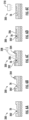
- the method 100 includes depositing a material composition 206 on the damage location 202 at the first temperature range, e.g., using spackling or slurry spraying.
- the system 200 may include an application device 208 for depositing the material composition 206 at the damage location 202.
- the application device 208 may be a spackling applicator, a slurry sprayer, or any other suitable application device.
- the material composition 206 described herein includes, at least, one or more sintering additives and one or more nucleating agents.
- the sintering additive(s) may be low melting glass, thermoset polymers pyrolyzed to ceramic, and/or organometallic precursor derived gel. Accordingly, the sintering additive(s) is configured to convert into crystalline phases during processing to restore toughness of the ceramic-based top layer of the multi-layer component after repair, whereas and the nucleating agent is configured to convert the sintering additive(s) to a ceramic material to reduce brittleness. Accordingly, the material composition 206 can be particularly useful in repairing the ceramic-based top layer 56 of the seal tooth 50 at an in-module level.
- the material composition 206 may be a slurry composition that can be applied to the damage location 202 of the alumina-based ceramic-based top layer 56 of a damaged seal tooth, such that the seal tooth can be repaired via sintering at lower temperatures.
- low melting glass can be SiO2 based, or non-silica based such as P2O5 based.
- these two families can be represented by M-SiO2 and N-P2O5.
- M includes SrO, ZnO, BaO, La 2 O 3 , Al 2 O 3 , B 2 O 3 , ZnO, Bi 2 O 3 , etc. or their combination.
- N includes CaO, Na 2 O, ZnO and Fe 2 O 3 etc., or their combination.
- examples of nucleating agents are V 2 O 5 , Cr 2 O 3 , Ba 3 (PO4) 2 , TiO 2 and Fe 2 O 3 .
- the method 100 includes removing the protective layer 204 after depositing the material composition 206 at the damage location 202. Furthermore, as shown in FIG. 6E , the method 100 includes applying localized curing to the material composition 206 deposited at the damage location at a second temperature range. For example, as shown, the curing may be completed using any suitable heat source 210 such as a heater, a heat exchanger, heated air, a heated light, etc. Moreover, in certain embodiments, after applying the localized curing to the material composition 206 deposited at the damage location 202 at the second temperature range, the multi-layer component 206 has a uniform density across the multi-layer component (i.e., from one side of the damage location 202 to the other).
- a method of repairing a multi-layer component of an engine in-module comprising: identifying a damage location on the multi-layer component having at least one defect, the at least one defect extending at least partially into a ceramic-based top layer of the multi-layer component; depositing a material composition at a first temperature range onto the damage location so as to cover the damage location, the material composition comprising one or more sintering additives; and applying localized curing at a second temperature range to the material composition deposited at the damage location, the second temperature range being higher than the first temperature range.
- the material composition further comprises a nucleating agent.
- the one or more sintering additives comprise low melting glass.
- depositing the material composition into the damage location at the first temperature range further comprises at least one of spackling or slurry spraying.
- the multi-layer component comprises a uniform density across the multi-layer component.
- the first temperature range comprises temperatures ranging from about 15 degrees Celsius (°C) to about 30°C.
- the second temperature range comprises temperatures equal to or less than about 650 degrees Celsius (°C).
- the ceramic-based top layer is constructed of an alumina-based alloy.
- the multi-layer component of the engine comprises one or more seal teeth of a seal of the engine.
- a system for repairing a ceramic-based top layer of a multi-layer component of an engine in-module comprising: a material composition for covering a defect in the ceramic-based top layer, the material composition comprising a sintering additive and a nucleating agent; and a heat source for applying localized heat to the material composition at the damage location to cure the material composition, wherein the sintering additive converts crystalline phases during processing to restore toughness of the ceramic-based top layer of the multi-layer component after repair, and wherein the nucleating agent converts the sintering additive to a ceramic material to reduce brittleness at the multi-layer component after repair.
Landscapes
- Engineering & Computer Science (AREA)
- Mechanical Engineering (AREA)
- General Engineering & Computer Science (AREA)
- Structures Of Non-Positive Displacement Pumps (AREA)
Applications Claiming Priority (2)
| Application Number | Priority Date | Filing Date | Title |
|---|---|---|---|
| IN202311058478 | 2023-08-31 | ||
| US18/536,780 US20250073829A1 (en) | 2023-08-31 | 2023-12-12 | System and method of repairing a multi-layer component of an engine |
Publications (1)
| Publication Number | Publication Date |
|---|---|
| EP4517044A1 true EP4517044A1 (de) | 2025-03-05 |
Family
ID=89941096
Family Applications (1)
| Application Number | Title | Priority Date | Filing Date |
|---|---|---|---|
| EP24157467.2A Pending EP4517044A1 (de) | 2023-08-31 | 2024-02-13 | System und verfahren zur reparatur einer mehrschichtigen komponente eines motors |
Country Status (1)
| Country | Link |
|---|---|
| EP (1) | EP4517044A1 (de) |
Citations (4)
| Publication number | Priority date | Publication date | Assignee | Title |
|---|---|---|---|---|
| US20050228098A1 (en) * | 2004-04-07 | 2005-10-13 | General Electric Company | Field repairable high temperature smooth wear coating |
| EP1739204B1 (de) * | 2005-06-29 | 2010-12-15 | General Electric Company | Vor Ort reparierbare hohe Temperatur glatte verschleissfeste Beschichtung |
| US10384978B2 (en) * | 2016-08-22 | 2019-08-20 | General Electric Company | Thermal barrier coating repair compositions and methods of use thereof |
| US20210396181A1 (en) * | 2020-06-19 | 2021-12-23 | General Electric Company | Methods and materials for repairing a thermal barrier coating of a gas turbine component |
-
2024
- 2024-02-13 EP EP24157467.2A patent/EP4517044A1/de active Pending
Patent Citations (4)
| Publication number | Priority date | Publication date | Assignee | Title |
|---|---|---|---|---|
| US20050228098A1 (en) * | 2004-04-07 | 2005-10-13 | General Electric Company | Field repairable high temperature smooth wear coating |
| EP1739204B1 (de) * | 2005-06-29 | 2010-12-15 | General Electric Company | Vor Ort reparierbare hohe Temperatur glatte verschleissfeste Beschichtung |
| US10384978B2 (en) * | 2016-08-22 | 2019-08-20 | General Electric Company | Thermal barrier coating repair compositions and methods of use thereof |
| US20210396181A1 (en) * | 2020-06-19 | 2021-12-23 | General Electric Company | Methods and materials for repairing a thermal barrier coating of a gas turbine component |
Similar Documents
| Publication | Publication Date | Title |
|---|---|---|
| US10036259B2 (en) | Turbine blade having film cooling hole arrangement | |
| US20140000286A1 (en) | Gas turbine engine turbine vane airfoil profile | |
| US20200141247A1 (en) | Component for a turbine engine with a film hole | |
| US20180223870A1 (en) | Coated Flange Bolt Hole and Methods of Forming the Same | |
| EP3730748A1 (de) | Verfahren und system zur bearbeitung eines abreibbaren materials eines turbofantriebwerks | |
| EP3202954B1 (de) | Reparatur einer beschichtung mit einem vorkonfigurierten beschichtungspflaster | |
| US11976566B2 (en) | Fatigue resistant blade outer air seal | |
| US11898459B1 (en) | Turbine blade cooling hole arrangement | |
| EP4053376A1 (de) | Systeme und verfahren für gehäusereparatur | |
| EP4517044A1 (de) | System und verfahren zur reparatur einer mehrschichtigen komponente eines motors | |
| US20250073829A1 (en) | System and method of repairing a multi-layer component of an engine | |
| US11293296B2 (en) | Method for manufacturing an annular casing equipping a turbomachine | |
| US11724969B2 (en) | Coating for improved surface finish | |
| US11034842B2 (en) | Coating for improved surface finish | |
| US12583064B2 (en) | Machining of ceramic matrix composite during preforming and partial densification | |
| EP4086433B1 (de) | Dichtungsanordnung mit dichtungsbogensegment | |
| EP3748133B1 (de) | Ermüdungsbeständige schaufelaussenluftdichtung | |
| US11143037B1 (en) | Turbine blade cooling hole arrangement | |
| EP3708782B1 (de) | Boas und verfahren zur herstellung von boas mit ermüdungsbeständigen kühleinlässen | |
| EP3940198A1 (de) | Mehrringabstandshalter für rotorstapelanordnung eines gasturbinentriebwerks | |
| US10677083B2 (en) | Blade outer air seal for a gas turbine engine | |
| EP4357587A1 (de) | Integral beschaufelter rotor für ein gasturbinentriebwerk, gasturbinentriebwerk und verfahren zur herstellung eines integral beschaufelten rotors eines gasturbinentriebwerks | |
| US11098591B1 (en) | Turbine blade with contoured fillet | |
| US20250257694A1 (en) | Gas turbine engine |
Legal Events
| Date | Code | Title | Description |
|---|---|---|---|
| PUAI | Public reference made under article 153(3) epc to a published international application that has entered the european phase |
Free format text: ORIGINAL CODE: 0009012 |
|
| STAA | Information on the status of an ep patent application or granted ep patent |
Free format text: STATUS: THE APPLICATION HAS BEEN PUBLISHED |
|
| AK | Designated contracting states |
Kind code of ref document: A1 Designated state(s): AL AT BE BG CH CY CZ DE DK EE ES FI FR GB GR HR HU IE IS IT LI LT LU LV MC ME MK MT NL NO PL PT RO RS SE SI SK SM TR |
|
| STAA | Information on the status of an ep patent application or granted ep patent |
Free format text: STATUS: REQUEST FOR EXAMINATION WAS MADE |
|
| 17P | Request for examination filed |
Effective date: 20250819 |