EP4517059A1 - Durch partielle abgase verstärkte kondensation - Google Patents
Durch partielle abgase verstärkte kondensation Download PDFInfo
- Publication number
- EP4517059A1 EP4517059A1 EP24197394.0A EP24197394A EP4517059A1 EP 4517059 A1 EP4517059 A1 EP 4517059A1 EP 24197394 A EP24197394 A EP 24197394A EP 4517059 A1 EP4517059 A1 EP 4517059A1
- Authority
- EP
- European Patent Office
- Prior art keywords
- flow
- exhaust gas
- gas flow
- condenser
- exhaust
- Prior art date
- Legal status (The legal status is an assumption and is not a legal conclusion. Google has not performed a legal analysis and makes no representation as to the accuracy of the status listed.)
- Pending
Links
Images


Classifications
-
- F—MECHANICAL ENGINEERING; LIGHTING; HEATING; WEAPONS; BLASTING
- F01—MACHINES OR ENGINES IN GENERAL; ENGINE PLANTS IN GENERAL; STEAM ENGINES
- F01K—STEAM ENGINE PLANTS; STEAM ACCUMULATORS; ENGINE PLANTS NOT OTHERWISE PROVIDED FOR; ENGINES USING SPECIAL WORKING FLUIDS OR CYCLES
- F01K23/00—Plants characterised by more than one engine delivering power external to the plant, the engines being driven by different fluids
- F01K23/02—Plants characterised by more than one engine delivering power external to the plant, the engines being driven by different fluids the engine cycles being thermally coupled
- F01K23/06—Plants characterised by more than one engine delivering power external to the plant, the engines being driven by different fluids the engine cycles being thermally coupled combustion heat from one cycle heating the fluid in another cycle
- F01K23/10—Plants characterised by more than one engine delivering power external to the plant, the engines being driven by different fluids the engine cycles being thermally coupled combustion heat from one cycle heating the fluid in another cycle with exhaust fluid of one cycle heating the fluid in another cycle
-
- F—MECHANICAL ENGINEERING; LIGHTING; HEATING; WEAPONS; BLASTING
- F01—MACHINES OR ENGINES IN GENERAL; ENGINE PLANTS IN GENERAL; STEAM ENGINES
- F01N—GAS-FLOW SILENCERS OR EXHAUST APPARATUS FOR MACHINES OR ENGINES IN GENERAL; GAS-FLOW SILENCERS OR EXHAUST APPARATUS FOR INTERNAL-COMBUSTION ENGINES
- F01N3/00—Exhaust or silencing apparatus having means for purifying, rendering innocuous, or otherwise treating exhaust
- F01N3/08—Exhaust or silencing apparatus having means for purifying, rendering innocuous, or otherwise treating exhaust for rendering innocuous
- F01N3/10—Exhaust or silencing apparatus having means for purifying, rendering innocuous, or otherwise treating exhaust for rendering innocuous by thermal or catalytic conversion of noxious components of exhaust
- F01N3/18—Exhaust or silencing apparatus having means for purifying, rendering innocuous, or otherwise treating exhaust for rendering innocuous by thermal or catalytic conversion of noxious components of exhaust characterised by methods of operation; Control
-
- F—MECHANICAL ENGINEERING; LIGHTING; HEATING; WEAPONS; BLASTING
- F01—MACHINES OR ENGINES IN GENERAL; ENGINE PLANTS IN GENERAL; STEAM ENGINES
- F01N—GAS-FLOW SILENCERS OR EXHAUST APPARATUS FOR MACHINES OR ENGINES IN GENERAL; GAS-FLOW SILENCERS OR EXHAUST APPARATUS FOR INTERNAL-COMBUSTION ENGINES
- F01N3/00—Exhaust or silencing apparatus having means for purifying, rendering innocuous, or otherwise treating exhaust
- F01N3/08—Exhaust or silencing apparatus having means for purifying, rendering innocuous, or otherwise treating exhaust for rendering innocuous
- F01N3/10—Exhaust or silencing apparatus having means for purifying, rendering innocuous, or otherwise treating exhaust for rendering innocuous by thermal or catalytic conversion of noxious components of exhaust
- F01N3/24—Exhaust or silencing apparatus having means for purifying, rendering innocuous, or otherwise treating exhaust for rendering innocuous by thermal or catalytic conversion of noxious components of exhaust characterised by constructional aspects of converting apparatus
-
- F—MECHANICAL ENGINEERING; LIGHTING; HEATING; WEAPONS; BLASTING
- F02—COMBUSTION ENGINES; HOT-GAS OR COMBUSTION-PRODUCT ENGINE PLANTS
- F02C—GAS-TURBINE PLANTS; AIR INTAKES FOR JET-PROPULSION PLANTS; CONTROLLING FUEL SUPPLY IN AIR-BREATHING JET-PROPULSION PLANTS
- F02C3/00—Gas-turbine plants characterised by the use of combustion products as the working fluid
- F02C3/20—Gas-turbine plants characterised by the use of combustion products as the working fluid using a special fuel, oxidant, or dilution fluid to generate the combustion products
- F02C3/30—Adding water, steam or other fluids for influencing combustion, e.g. to obtain cleaner exhaust gases
- F02C3/305—Increasing the power, speed, torque or efficiency of a gas turbine or the thrust of a turbojet engine by injecting or adding water, steam or other fluids
-
- F—MECHANICAL ENGINEERING; LIGHTING; HEATING; WEAPONS; BLASTING
- F02—COMBUSTION ENGINES; HOT-GAS OR COMBUSTION-PRODUCT ENGINE PLANTS
- F02C—GAS-TURBINE PLANTS; AIR INTAKES FOR JET-PROPULSION PLANTS; CONTROLLING FUEL SUPPLY IN AIR-BREATHING JET-PROPULSION PLANTS
- F02C6/00—Plural gas-turbine plants; Combinations of gas-turbine plants with other apparatus; Adaptations of gas-turbine plants for special use
- F02C6/18—Plural gas-turbine plants; Combinations of gas-turbine plants with other apparatus; Adaptations of gas-turbine plants for special use using the waste heat of gas-turbine plants outside the plants themselves, e.g. gas-turbine power heat plants
-
- F—MECHANICAL ENGINEERING; LIGHTING; HEATING; WEAPONS; BLASTING
- F02—COMBUSTION ENGINES; HOT-GAS OR COMBUSTION-PRODUCT ENGINE PLANTS
- F02C—GAS-TURBINE PLANTS; AIR INTAKES FOR JET-PROPULSION PLANTS; CONTROLLING FUEL SUPPLY IN AIR-BREATHING JET-PROPULSION PLANTS
- F02C7/00—Features, components parts, details or accessories, not provided for in, or of interest apart form groups F02C1/00 - F02C6/00; Air intakes for jet-propulsion plants
- F02C7/12—Cooling of plants
- F02C7/14—Cooling of plants of fluids in the plant, e.g. lubricant or fuel
- F02C7/141—Cooling of plants of fluids in the plant, e.g. lubricant or fuel of working fluid
- F02C7/143—Cooling of plants of fluids in the plant, e.g. lubricant or fuel of working fluid before or between the compressor stages
-
- F—MECHANICAL ENGINEERING; LIGHTING; HEATING; WEAPONS; BLASTING
- F05—INDEXING SCHEMES RELATING TO ENGINES OR PUMPS IN VARIOUS SUBCLASSES OF CLASSES F01-F04
- F05D—INDEXING SCHEME FOR ASPECTS RELATING TO NON-POSITIVE-DISPLACEMENT MACHINES OR ENGINES, GAS-TURBINES OR JET-PROPULSION PLANTS
- F05D2270/00—Control
- F05D2270/01—Purpose of the control system
- F05D2270/08—Purpose of the control system to produce clean exhaust gases
Definitions
- the present disclosure relates generally to an aircraft propulsion system that includes a steam generation system transforming water extracted from an exhaust gas flow into steam for injected into a core flow.
- Turbine engines compress incoming core airflow, mix the compressed airflow with fuel that is ignited in a combustor to generate an exhaust gas flow.
- Steam injection can provide improved propulsive efficiencies. Water recovered from the exhaust gas flow may be transformed into steam using thermal energy from the exhaust gas flow. Available cold sink temperatures may not be sufficient to efficiently condense water from the entire volume of exhaust gas flow.
- a turbine engine assembly includes, among other possible things, a compressor section where an inlet airflow is compressed, a combustor section where the compressed inlet airflow is mixed with fuel and ignited to generate an exhaust gas flow that is communicated through a core flow path, a turbine section through which the exhaust gas flow expands to generate a mechanical power output, the exhaust gas flow is split into a first exhaust gas flow and a second exhaust gas flow.
- the turbine engine assembly further includes a condenser where water from the second exhaust gas flow is condensed and extracted, and an evaporator system where thermal energy from at least the second exhaust gas flow is utilized to generate a steam flow from at least a portion of water that is extracted by the condenser for injection into a core flow path.
- the second exhaust gas flow is less than or equal to half of a total exhaust gas flow that is generated in the combustor section.
- the turbine engine assembly further includes a heat pump that is in thermal communication with a cold sink flow and the condenser.
- the heat pump is configured to cool the second exhaust gas flow in the condenser.
- the turbine engine assembly includes an exhaust mixer for merging the first exhaust gas flow and the second exhaust flow downstream from the condenser.
- the turbine engine assembly includes a turboexpander where steam flow generated by the evaporator system is expanded before communication to the combustor section.
- the exit steam flow from the turboexpander is reheated by the exhaust gas flow prior to communication to the combustor section.
- the turbine engine assembly includes a bleed air system where air drawn from the compressor section is used to cool the second exhaust gas flow in the condenser.
- the bleed air system includes a turboexpander through which the bleed air is expanded and cooled before communication to the condenser.
- the bleed air system further includes a heat exchanger for cooling the bleed air.
- the turbine engine assembly further includes a fuel system for communicating a non-carbon based fuel to the combustor section.
- An aircraft propulsion system includes, among other possible things, a propulsor for generating propulsive thrust, a core engine wherein inlet airflow is compressed, mixed with fuel and ignited to generate an exhaust gas flow that is expanded through a turbine section to generate shaft power that is utilized to drive the propulsor, the exhaust gas flow is split into a first exhaust gas flow and a second exhaust gas flow and the second exhaust gas flow is less than half of the exhaust gas flow, a condenser where water from the second exhaust gas flow is condensed and extracted, an evaporator system where thermal energy from at least the second exhaust gas flow is utilized to generate a steam flow from at least a portion of water that is extracted by the condenser for injection into a core flow path, and a cold sink that is in thermal communication with the second exhaust gas flow in the condenser for cooling the second exhaust gas flow.
- the cold sink includes a heat pump that is in thermal communication with a cold sink flow and the condenser.
- the heat pump is configured to cool the second exhaust gas flow in the condenser.
- the cold sink includes a cooled bleed air system where air drawn from the compressor section is cooled and communicated to the condenser to cool the second exhaust gas flow in the condenser.
- the bleed air system includes a heat exchanger for cooling the bleed air and a turboexpander through which the bleed air is expanded and cooled before communication to the condenser.
- the aircraft propulsion system includes an exhaust mixer for merging the first exhaust gas flow and the second exhaust flow downstream from the condenser.
- the aircraft propulsion system includes a turboexpander where steam flow generated by the evaporator system is expanded before communication to the core flow path and the exit steam flow from the turboexpander is reheated by the exhaust gas flow prior to communication to the core flow path.
- the aircraft propulsion system further includes a fuel system for communicating a non-carbon based fuel to a combustor section of the core engine.
- a method of operating an aircraft propulsion system includes, among other possible things, generating an exhaust flow that contains a mixture of steam, compressed air and fuel, splitting the generated exhaust flow into a first exhaust flow and a second exhaust flow with the second exhaust flow being less than half of the total generated exhaust flow, condensing and extracting water from the second exhaust flow, thermally communicating the second exhaust flow with a cold sink in the condenser for cooling the second exhaust flow, generating a steam flow with thermal energy from the generated exhaust flow, and at least portion of the steam flow is injected into a core flow path.
- the cold sink includes a heat pump that is in thermal communication with a cold sink flow and the condenser.
- the heat pump is configured to cool the second exhaust flow in the condenser.
- the cold sink includes a cooled bleed air system where air is drawn from the core flow path and communicated to the condenser to cool the second exhaust flow in the condenser.
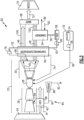
- Figure 1 schematically illustrates an example propulsion system 20 that condenses and extracts water from a partial portion of the exhaust gas flow to reduce difficulties incurred by attempting to extract water from all of the exhaust gas flow.
- the example propulsion system further includes additional features that improve cooling of the partial portion of the exhaust gas flow in a condenser system 54.
- the example propulsion system 20 includes a fan section 24 and a core engine 22.
- the core engine 22 includes a compressor section 26, a combustor section 28 and a turbine section 30 disposed along an engine longitudinal axis A.
- the fan section 24 drives a fan bypass airflow 42 along a bypass flow path B, while the compressor section 26 draws inlet air along a core flow path C as a core flow 44.
- the core flow 44 is compressed and communicated to the combustor section 28 where a compressed core airflow 44 is mixed with a fuel flow 38 and ignited to generate the exhaust gas flow 40.
- the exhaust gas flow 40 expands through the turbine section 30 where energy is extracted and utilized to drive the fan section 24 and the compressor section 26.
- a fuel system 32 including at least a fuel tank 34 and a fuel pump 36 to provide the fuel flow 38 to the combustor 28.
- the example fuel system 32 is configured to provide a hydrogen based fuel such as a liquid hydrogen (LH 2 ).
- a hydrogen based fuel such as a liquid hydrogen (LH 2 ).
- LH 2 liquid hydrogen
- hydrogen is disclosed by way of example, other non-carbon based fuels could be utilized and are within the contemplation of this disclosure.
- the disclosed features may also be beneficial in an engine configured to operate with traditional carbon fuels and/or biofuels, such as sustainable aviation fuel.
- An evaporator system 50 and a condenser 54 are disposed downstream of the turbine section 30 and receive portions of the exhaust gas flow 40.
- the evaporator system 50 utilizes thermal energy from the exhaust gas flow 40 to generate a steam flow 52 from water 56 extracted by the condenser 54.
- the extracted water 56 is gathered in a tank 58 and pressurized by a pump 60 for communication to the evaporator system 50 as a pressurized water flow 62.
- the bypass airflow 42 is utilized as a cold sink 66 in a heat pump 64 associated with the condenser 54 to cool a portion 48 of the exhaust gas flow.
- the steam flow 52 from the evaporator 50 is communicated to the combustor 28 and combined with the core flow 44 to increase mass flow through the turbine section 30 and thereby increase engine power and efficiency.
- the propulsion system 20 has an increased power output utilizing the injected steam flow 74 due to increased mass flow through the turbine section 30 without a corresponding increase in work from the compressor section 26.
- the example steam flow 74 is shown as injected into the combustor 28, the steam flow 74 may be injected at other locations along the core flow path C and remain with the contemplation of this disclosure. For example, some or all of the steam flow 74 could be injected in an inlet of the propulsion system 20, the compressor section 26, and/or the turbine section 30.
- the exhaust gas flow 40 is a mix of steam, and components from combustion of fuel.
- the components from combustion can include, among other possible components, nitrogen, carbon dioxide and oxygen. These combustion components reduce the efficiency of the condenser 54 in condensing liquid water from the exhaust gas flow 40.
- the bypass airflow 42 has a limited capacity for cooling that may further reduce condenser efficiencies.
- the example propulsion system provides for increased condenser efficiencies by separating the exhaust gas flow 40 into a first exhaust gas flow 46 communicated through a first passage 100 and a second exhaust gas flow 48 communicated through a second passage 102. Only the second exhaust gas flow 48 is communicated to the condenser 54 for extraction of water.
- the second exhaust gas flow 48 is equal to or less than half of the total exhaust gas flow 40 emitted from an outlet of the turbine section 30.
- the second exhaust gas flow 48 has a flow volume of between 10% and 25% that of the first exhaust gas flow 46.
- the split between the first exhaust gas flow 46 and the second exhaust gas flow 48 may range from around 90% of the exhaust gas flow 40 communicated through the condenser 54 to as little as about 10% of the total exhaust gas flow 40 communicated through the condenser 54.
- the water extracted is less than or equal to around 25% of the total core mass flow. In another example embodiment, the water extracted is less than or equal to around 10% of the total core mass flow. Moreover, in another example embodiment, the relatively smaller flow volume of the second exhaust gas flow 48 that is communicated through the condenser 54 allows a lower flow volume of cold sink 66 to condense and extract water.
- the example cold sink 66 is associated with a heat pump 64 in thermal communication with the condenser 54.
- the heat pump 64 provides for movement of thermal energy away from the condenser 54 and to the cold sink 66.
- the example heat pump 64 may be of any configuration that provides for movement of thermal energy away from the condenser 54.
- the heat pump 64 comprises a refrigerant circuit circulating a refrigerant between the second exhaust gas flow 48 and the cold sink 66.
- the example heat pump 64 provides an increase in the available cold sink 66.
- Water extracted from the second exhaust gas flow 48 is pressurized by the pump 60 and communicated as the pressurized flow of water to the evaporator 50.
- the pressurized water is heated by both the first exhaust gas flow 46 and the second exhaust gas flow 48 to provide the steam flow 52 that is communicated to the combustor 28.
- the first and second exhaust gas flows 46 and 48 are recombined into a combined exhaust flow 72 by a mixer 68.
- the combined exhaust gas flow 72 is exhausted to the ambient environment through a nozzle 70.
- thermal energy from both the first and second exhaust gas flows 46, 48 may be communicated to the evaporator 50.
- thermal energy from only one of the first and second exhaust gas flows 46, 48 is communicated to the evaporator 50.
- the steam turbine 76 provides shaft power 106 and communicates the expanded steam flow back through an evaporator/super heater 78 to generate a superheated steam flow 74.
- the initial steam flow 52 is expanded through the steam turbine 76 to generate shaft power 106 that may be utilized to drive accessory components schematically indicated at 108.
- the accessory components 108 may include, among other possible devices, a pump, generator and/or actuator.
- Steam exiting the steam turbine 76 may be include both vapor and liquid and is reheated in the evaporator/superheater 78.
- the disclosed example embodiment illustrates the evaporator/superheater 78 as a single device, it may be configured as separate devices to accommodate application specific limitations.
- the evaporator/superheater 78 may be separate parts to enable exposure to different temperatures of the exhaust gas flow 40 to provide the evaporation and superheating functions.
- the second condenser 104 provides for an initial condensation and extraction of water as indicated at 110.
- bypass fan airflow 42 is utilized as the cold sink for the second condenser 104.
- the second exhaust gas flow 48 is initially cooled in the second condenser 104 to provide for the extraction of an initial amount of water as indicated at 110.
- the cooled second exhaust gas flow 48 from the second condenser 104 is communicated to the condenser 54 for extraction of additional water.
- the cooler second exhaust gas flow 48 provided to the condenser 54 is further cooled by the heat pump 64 and the cold sink flow 66.
- the additional condenser 104 provides an additional cooling of the second exhaust gas flow 48 that further improves water extraction efficiency.
- the bleed airflow 90 is cooled in a heat exchanger 86.
- the example heat exchanger 86 is in thermal communication with the bypass fan airflow 42 to provide an initial cooling of the bleed airflow 90.
- the bleed airflow 90 is expanded through a bleed air turbine 88 (e.g., turboexpander) for further cooling.
- the bleed airflow exhausted from the bleed air turbine 88 is provided as a cooled bleed airflow 92 and is cooled to a temperature less than that of the fan bypass airflow 42 and communicated to the condenser 54.
- the cooled bleed airflow 92 is placed in thermal communication with only the second exhaust gas flow 48 in the condenser 54 and subsequently exhausted as indicated at 96.
- the exhausted cooled bleed airflow 96 may be exhausted to the ambient environment or routed to other areas of the propulsion system that require cooling.
Landscapes
- Engineering & Computer Science (AREA)
- Chemical & Material Sciences (AREA)
- Combustion & Propulsion (AREA)
- Mechanical Engineering (AREA)
- General Engineering & Computer Science (AREA)
- Chemical Kinetics & Catalysis (AREA)
- Health & Medical Sciences (AREA)
- Toxicology (AREA)
- Engine Equipment That Uses Special Cycles (AREA)
Applications Claiming Priority (1)
| Application Number | Priority Date | Filing Date | Title |
|---|---|---|---|
| US18/457,486 US12264609B2 (en) | 2023-08-29 | 2023-08-29 | Partial exhaust gas augmented condensation |
Publications (1)
| Publication Number | Publication Date |
|---|---|
| EP4517059A1 true EP4517059A1 (de) | 2025-03-05 |
Family
ID=92627348
Family Applications (1)
| Application Number | Title | Priority Date | Filing Date |
|---|---|---|---|
| EP24197394.0A Pending EP4517059A1 (de) | 2023-08-29 | 2024-08-29 | Durch partielle abgase verstärkte kondensation |
Country Status (2)
| Country | Link |
|---|---|
| US (1) | US12264609B2 (de) |
| EP (1) | EP4517059A1 (de) |
Cited By (1)
| Publication number | Priority date | Publication date | Assignee | Title |
|---|---|---|---|---|
| US20250101917A1 (en) * | 2023-01-27 | 2025-03-27 | Rtx Corporation | Hydrogen steam injected turbine engine with turboexpander heat recovery |
Families Citing this family (1)
| Publication number | Priority date | Publication date | Assignee | Title |
|---|---|---|---|---|
| US12529333B2 (en) * | 2022-07-22 | 2026-01-20 | Rtx Corporation | Partial exhaust condensation with cryogenic assisted bottoming cycle |
Citations (5)
| Publication number | Priority date | Publication date | Assignee | Title |
|---|---|---|---|---|
| US4248039A (en) * | 1978-12-06 | 1981-02-03 | International Power Technology, Inc. | Regenerative parallel compound dual fluid heat engine |
| US20070214766A1 (en) * | 2006-03-16 | 2007-09-20 | Mitsuru Obana | Gas turbine engine |
| US20120111001A1 (en) * | 2009-07-21 | 2012-05-10 | Renault Trucks | Engine arrangement with an improved exhaust heat recovery arrangement |
| US20180371954A1 (en) * | 2015-12-11 | 2018-12-27 | Hieta Technologies Limited | Inverted brayton cycle heat engine |
| US20210207500A1 (en) * | 2018-05-22 | 2021-07-08 | MTU Aero Engines AG | Exhaust-gas treatment device, aircraft propulsion system, and method for treating an exhaust-gas stream |
Family Cites Families (4)
| Publication number | Priority date | Publication date | Assignee | Title |
|---|---|---|---|---|
| US8707701B2 (en) | 2008-10-20 | 2014-04-29 | Burkhart Technologies, Llc | Ultra-high-efficiency engines and corresponding thermodynamic system |
| US12129774B2 (en) * | 2022-05-19 | 2024-10-29 | Rtx Corporation | Hydrogen fueled turbine engine pinch point water separator |
| US11920526B1 (en) * | 2022-08-12 | 2024-03-05 | Rtx Corporation | Inter-cooled preheat of steam injected turbine engine |
| US20240102416A1 (en) * | 2022-09-23 | 2024-03-28 | Raytheon Technologies Corporation | Steam injected inter-turbine burner engine |
-
2023
- 2023-08-29 US US18/457,486 patent/US12264609B2/en active Active
-
2024
- 2024-08-29 EP EP24197394.0A patent/EP4517059A1/de active Pending
Patent Citations (5)
| Publication number | Priority date | Publication date | Assignee | Title |
|---|---|---|---|---|
| US4248039A (en) * | 1978-12-06 | 1981-02-03 | International Power Technology, Inc. | Regenerative parallel compound dual fluid heat engine |
| US20070214766A1 (en) * | 2006-03-16 | 2007-09-20 | Mitsuru Obana | Gas turbine engine |
| US20120111001A1 (en) * | 2009-07-21 | 2012-05-10 | Renault Trucks | Engine arrangement with an improved exhaust heat recovery arrangement |
| US20180371954A1 (en) * | 2015-12-11 | 2018-12-27 | Hieta Technologies Limited | Inverted brayton cycle heat engine |
| US20210207500A1 (en) * | 2018-05-22 | 2021-07-08 | MTU Aero Engines AG | Exhaust-gas treatment device, aircraft propulsion system, and method for treating an exhaust-gas stream |
Cited By (2)
| Publication number | Priority date | Publication date | Assignee | Title |
|---|---|---|---|---|
| US20250101917A1 (en) * | 2023-01-27 | 2025-03-27 | Rtx Corporation | Hydrogen steam injected turbine engine with turboexpander heat recovery |
| US12486801B2 (en) * | 2023-01-27 | 2025-12-02 | Rtx Corporation | Hydrogen steam injected turbine engine with turboexpander heat recovery |
Also Published As
| Publication number | Publication date |
|---|---|
| US12264609B2 (en) | 2025-04-01 |
| US20250075649A1 (en) | 2025-03-06 |
Similar Documents
| Publication | Publication Date | Title |
|---|---|---|
| US12215622B1 (en) | Partial exhaust condensation intercooling | |
| EP4517059A1 (de) | Durch partielle abgase verstärkte kondensation | |
| US12129774B2 (en) | Hydrogen fueled turbine engine pinch point water separator | |
| US12270333B2 (en) | Partial exhaust gas condensation with inverse Brayton control | |
| US12286907B2 (en) | Increased water heat absorption capacity for steam injected turbine engine | |
| US12180893B2 (en) | Hydrogen steam injected turbine engine with turboexpander heat recovery | |
| US20230374938A1 (en) | Hydrogen fueled turbine engine condenser duct | |
| US12577907B2 (en) | Inter-turbine burner in recuperation cycle engine | |
| EP4407164A1 (de) | Geteilter verdampfer für einen dampfeinspritzenden turbinenmotor | |
| EP4481172A1 (de) | Durch kryogene lufttrennung verbesserte gasturbine | |
| EP4279721B1 (de) | Wasserstoffdampfeinspritzturbinenmotor mit rückströmung | |
| US12473858B2 (en) | Partial exhaust bottoming cycle | |
| US20240141831A1 (en) | Hydrogen steam injected turbine engine with cooled cooling air | |
| EP4726197A1 (de) | Schubumkehrvorrichtung in einem kondensatorausgangskanal | |
| US20240360791A1 (en) | Cryo-assisted bottoming cycle heat source sequencing | |
| US12510023B1 (en) | Fan case mounted evaporator for aircraft turbine engine | |
| US20260063068A1 (en) | Evaporator system within an inner fixed structure of an aircraft propulsion system | |
| US20260015969A1 (en) | Fuel cell exhaust condensation with turbomachinery water augmentation using cryogenic bottoming cycle | |
| EP4678893A1 (de) | Kryounterstützte bottoming-zyklus-wärmequellensequenzierung |
Legal Events
| Date | Code | Title | Description |
|---|---|---|---|
| PUAI | Public reference made under article 153(3) epc to a published international application that has entered the european phase |
Free format text: ORIGINAL CODE: 0009012 |
|
| STAA | Information on the status of an ep patent application or granted ep patent |
Free format text: STATUS: THE APPLICATION HAS BEEN PUBLISHED |
|
| AK | Designated contracting states |
Kind code of ref document: A1 Designated state(s): AL AT BE BG CH CY CZ DE DK EE ES FI FR GB GR HR HU IE IS IT LI LT LU LV MC ME MK MT NL NO PL PT RO RS SE SI SK SM TR |
|
| STAA | Information on the status of an ep patent application or granted ep patent |
Free format text: STATUS: REQUEST FOR EXAMINATION WAS MADE |
|
| 17P | Request for examination filed |
Effective date: 20250905 |