EP4517085A1 - Windturbine mit turbinenschaufelbelastungssteuerung - Google Patents
Windturbine mit turbinenschaufelbelastungssteuerung Download PDFInfo
- Publication number
- EP4517085A1 EP4517085A1 EP23193682.4A EP23193682A EP4517085A1 EP 4517085 A1 EP4517085 A1 EP 4517085A1 EP 23193682 A EP23193682 A EP 23193682A EP 4517085 A1 EP4517085 A1 EP 4517085A1
- Authority
- EP
- European Patent Office
- Prior art keywords
- wind turbine
- turbine blade
- electrical
- test signal
- domain reflectometry
- Prior art date
- Legal status (The legal status is an assumption and is not a legal conclusion. Google has not performed a legal analysis and makes no representation as to the accuracy of the status listed.)
- Granted
Links
Images


Classifications
-
- F—MECHANICAL ENGINEERING; LIGHTING; HEATING; WEAPONS; BLASTING
- F03—MACHINES OR ENGINES FOR LIQUIDS; WIND, SPRING, OR WEIGHT MOTORS; PRODUCING MECHANICAL POWER OR A REACTIVE PROPULSIVE THRUST, NOT OTHERWISE PROVIDED FOR
- F03D—WIND MOTORS
- F03D17/00—Monitoring or testing of wind motors, e.g. diagnostics
- F03D17/027—Monitoring or testing of wind motors, e.g. diagnostics characterised by the component being monitored or tested
- F03D17/028—Blades
-
- F—MECHANICAL ENGINEERING; LIGHTING; HEATING; WEAPONS; BLASTING
- F03—MACHINES OR ENGINES FOR LIQUIDS; WIND, SPRING, OR WEIGHT MOTORS; PRODUCING MECHANICAL POWER OR A REACTIVE PROPULSIVE THRUST, NOT OTHERWISE PROVIDED FOR
- F03D—WIND MOTORS
- F03D17/00—Monitoring or testing of wind motors, e.g. diagnostics
- F03D17/009—Monitoring or testing of wind motors, e.g. diagnostics characterised by the purpose
- F03D17/011—Monitoring or testing of wind motors, e.g. diagnostics characterised by the purpose for monitoring mechanical loads or assessing fatigue; for monitoring structural integrity
-
- F—MECHANICAL ENGINEERING; LIGHTING; HEATING; WEAPONS; BLASTING
- F05—INDEXING SCHEMES RELATING TO ENGINES OR PUMPS IN VARIOUS SUBCLASSES OF CLASSES F01-F04
- F05B—INDEXING SCHEME RELATING TO WIND, SPRING, WEIGHT, INERTIA OR LIKE MOTORS, TO MACHINES OR ENGINES FOR LIQUIDS COVERED BY SUBCLASSES F03B, F03D AND F03G
- F05B2270/00—Control
- F05B2270/30—Control parameters, e.g. input parameters
- F05B2270/331—Mechanical loads
-
- F—MECHANICAL ENGINEERING; LIGHTING; HEATING; WEAPONS; BLASTING
- F05—INDEXING SCHEMES RELATING TO ENGINES OR PUMPS IN VARIOUS SUBCLASSES OF CLASSES F01-F04
- F05B—INDEXING SCHEME RELATING TO WIND, SPRING, WEIGHT, INERTIA OR LIKE MOTORS, TO MACHINES OR ENGINES FOR LIQUIDS COVERED BY SUBCLASSES F03B, F03D AND F03G
- F05B2270/00—Control
- F05B2270/30—Control parameters, e.g. input parameters
- F05B2270/332—Maximum loads or fatigue criteria
-
- Y—GENERAL TAGGING OF NEW TECHNOLOGICAL DEVELOPMENTS; GENERAL TAGGING OF CROSS-SECTIONAL TECHNOLOGIES SPANNING OVER SEVERAL SECTIONS OF THE IPC; TECHNICAL SUBJECTS COVERED BY FORMER USPC CROSS-REFERENCE ART COLLECTIONS [XRACs] AND DIGESTS
- Y02—TECHNOLOGIES OR APPLICATIONS FOR MITIGATION OR ADAPTATION AGAINST CLIMATE CHANGE
- Y02E—REDUCTION OF GREENHOUSE GAS [GHG] EMISSIONS, RELATED TO ENERGY GENERATION, TRANSMISSION OR DISTRIBUTION
- Y02E10/00—Energy generation through renewable energy sources
- Y02E10/70—Wind energy
- Y02E10/72—Wind turbines with rotation axis in wind direction
Definitions
- the present invention relates to a wind turbine with a wind turbine blade strain control.
- the invention also relates to a method for determining a strain of a wind turbine blade of a wind turbine.
- Wind turbine blades of wind turbines are subjected to a large mechanical load. Excessive wind loads can result in an overload of the wind turbine blade, which can result in structural damages and failure of the wind turbine blade.
- LOPC Load-Optimized-Pitch-Control strategy
- it is the object of the present invention to create a wind turbine with a wind turbine blade strain control and a method for determining a strain of a wind turbine blade of a wind turbine which avoid complex measuring systems and/or ensure a precise strain measurement, e.g., point strain measurement and/or distributed strain measurement during operation of the wind turbine in a simple and inexpensive manner.
- the object is achieved by a wind turbine with a wind turbine blade strain control.
- the wind turbine comprises a tower, a nacelle, a rotor, a hub, a plurality of wind turbine blades, a generator and a controller for controlling the operation of the wind turbine.
- the wind turbine blades comprise a root section for engaging the hub, a tip end section and an intermediate section between the root section and the tip end section.
- the wind turbine blades comprise a spar-cap, extending between the root section and the tip end section.
- the wind turbine blade comprises a first electrical path from the root section of the wind turbine blade to the tip section of the wind turbine blade, a second electrical path from the tip section to the root section and an electrical time-domain reflectometry device, electrically connected to the first electrical path and the second electrical path for performing electrical time-domain reflectometry measurements within the first electrical path and the second electrical path.
- the wind turbine according to the invention may comprise a plurality of different components, which may be of conventional size, shape and/or material. With other words, the wind turbine can have an appearance, which does not necessarily differ from conventional wind turbines, when looked at from the outside.
- the wind turbine blade comprises the root section for fixing the wind turbine blade to the hub, e.g., to a pitch bearing of the hub.
- the root section has a round or oval cross-section and a root flange with a plurality of fixation bores for fixing the wind turbine blade to the hub, e.g., by bolts and nuts.
- the wind turbine blade comprises the tip end section.
- the tip end section constitutes a distal end of the wind turbine blade with respect to the hub.
- the tip end section can comprise a lightning rod, protruding from the tip end section, e.g., in a direction away from the root section, e.g., parallel or substantially parallel to the longitudinal axis of the wind turbine blade.
- the spar-cap extends between the root section and the tip end section.
- the spar-cap extends over the complete intermediate section. Further preferred, the spar-cap extends into the root section and/or the tip end section.
- the spar-cap is configured for providing stability to the wind turbine blade. It is preferred that the spar-cap constitutes a part of the outer surface of the wind turbine blade.
- the wind turbine blade comprises two spar-caps, spaced apart and mutually connected by a shear web.
- the first electrical path and the second electrical path are constituted by an electrical conducting material, such as copper, aluminum, carbon fibers or the like.
- the electrical conduction material can be integrated into the wind turbine blade wall material or can be attached to an inside surface of the wind turbine blade wall, e.g., by glue, resin, a coating or the like.
- the electrical conducting material is configured for withstanding and transporting a current from a lightning strike from the tip end section to the root section.
- the first electrical path and/or the second electrical path is part of a lightning protection system of the turbine blade.
- the electrical conducting material can be in or at the spar-cap.
- the electrical time-domain reflectometry device is electrically connected to the first electrical path and/or the second electrical path.
- the electrical time-domain reflectometry device is located within the wind turbine blade, the hub or the nacelle.
- the electrical time-domain reflectometry device is configured for performing electrical time-domain reflectometry measurements within the first electrical path and the second electrical path. This can be executed, e.g., by sending an electrical impulse through the first electrical path and receiving the electrical impulse from the second electrical path.
- the electrical time-domain reflectometry device can determine the extent and distribution of strain and damages to the wind turbine blade with a high accuracy.
- strain control of the wind turbine blade can be performed.
- strain control can be considered as strain measurement.
- strain control comprises countermeasures to keep strain below a strain threshold.
- the controlled strain can be distributed strain and/or point strain.
- a wind turbine according to the invention has the advantage over conventional wind turbines that in a simple and inexpensive way the extent and distribution of strain and damages to the wind turbine blade can be determined reliably with a high accuracy. Even existing wind turbines can be provided with the strain control easily. Moreover, costly equipment can be saved. Furthermore, the strain can be controlled during operation of the wind turbine and in an inactive state. Thus, the determined strain data can be used for supporting the operation control of the wind turbine, e.g., to avoid damages to the wind turbine due to strong winds, and for determining cracks, delaminations, breakages or other damages within the structure of the wind turbine blade.
- a wind turbine can provide that the first electrical path and/or the second electrical path is provided by the spar-cap of the wind turbine blade.
- the first electrical path is provided by a first spar-cap of the wind turbine blade and the second electrical path is provided by a second spar-cap of the wind turbine blade, wherein the first spar-cap and the second spar-cap are electrically coupled at the tip end section.
- the first electrical path is provided by a first section of the spar-cap of the wind turbine blade and the second electrical path is provided by a second section of the spar-cap, wherein the first section and the second section are electrically coupled at the tip end section.
- the carbon fibers can constitute the electrical path.
- an electrical circuit is provided for the electrical time-domain reflectometry measurements. This has the advantage that in a simple and inexpensive way the integration of the strain control into existing wind turbine blades is improved. Moreover, due to the integration of the electrical paths into the spar-cap, damages of the spar-cap, which is a critical structure of the wind turbine blade, can be determined with high reliability and accuracy.
- the spar-cap comprises a carbon fiber.
- the spar-cap comprises a plurality of carbon fibers, carbon fiber planks or the like.
- the carbon fibers are impregnated with a resin.
- the spar-cap is manufactured as a fiber-reinforced plastic or fiber-reinforced polymer or the like, wherein the reinforcement fibers are carbon fibers or at least comprise carbon fibers.
- the first electrical path is provided by a first electrical conductor, which is attached to a first wall of the wind turbine blade and/or the second electrical path is provided by a second electrical conductor, which is attached to a second wall of the wind turbine blade.
- the first electrical conductor and/or the second electrical conductor can be attached to the spar-cap, especially at a side facing inside the wind turbine blade, e.g., next to the shear web.
- the first electrical conductor and/or the second electrical conductor can be configured as a wire or the like.
- the material of the electrical conductor can be metal, such as copper, aluminum or the like.
- the material of the electrical conductor can be carbon, e.g., in the form of a fiber strand, fiber slab or the like.
- the fibers can be laminated to the spar-cap, e.g., by a resin, plastic, or the like. This has the advantage that in a simple and inexpensive way the first electrical path and the second electrical path are provided.
- the first electrical conductor and/or the second electrical conductor is configured as a metal band.
- a metal band can be also denoted as " metal tape " or " metal strip " .
- the metal band has a length from the root section to the tip end section, which is substantially greater than a width of the metal band. Further preferred, the metal band has a width, which is substantially greater than a thickness of the metal band.
- a preferred metal is copper or, alternatively, aluminum.
- the metal band is glued to an inside surface of the wind turbine blade, e.g., to the spar-cap. This has the advantage that in a simple and inexpensive way the condition of a relatively large area of the wind turbine blade can be inspected reliably with respect to strains, cracks or other damages.
- the electrical time-domain reflectometry device is electrically connected to a lightning protection system of the wind turbine blade.
- the lightning protection system extends from the tip end section to the root section and is connected to the ground, preferably, through or aside the tower of the wind turbine.
- the electrical conductors of the lightning system fulfil at least two different tasks for the wind turbine. This has the advantage that in a simple and inexpensive way, the resources of the wind turbine are used in a very effective way.
- the controller is configured to prepare an analysis of a test signal response of the electrical time-domain reflectometry device and to operate the wind turbine in dependence of this analysis.
- the parameters of the wind turbine that can be controlled in this regards can be a pitch angle of the wind turbine blades, a yaw angle, a flap angle, generator torque, stall device actuation or the like.
- data of a strain within the wind turbine blade due to strong winds and a first pitch angle of the wind turbine blade can be used by the control to change the first pitch angle to a second pitch angle, for which the wind turbine blade is less exposed to the wind, when the strain is above a predefined upper strain threshold, or to change the first pitch angle to a third pitch angle, for which the wind turbine blade is more exposed to the wind, when the strain is below a predefined lower strain threshold.
- the preparation of the analysis of the test signal response comprises a comparison of an actual test signal response with previous test signal responses for the same wind turbine blade and/or a comparison of actual test signal responses for a first wind turbine blade of the wind turbine blades with the actual test signal responses for a second wind turbine blade of the wind turbine blades and/or an application of the test signal response to a computer model of the wind turbine blade.
- other variables such as wind speed, precipitation, pitch angle, yaw angle or the like, are considered for the analysis.
- the controller comprises an artificial intelligence for preparing the analysis and/or for adjusting the computer model of the wind turbine, e.g., considering measurement data of the electrical time-domain reflectometry device, additional sensors or the like. This has the advantage that in a simple and inexpensive way the extent and distribution of strain and damages to the wind turbine blade can be determined an improved reliability and with a higher accuracy.
- the electrical time-domain reflectometry device is arranged at the root section of the wind turbine blade or the hub.
- the root section of the wind turbine blade and the hub comprise a hollow space, which is providing enough space for the electrical time-domain reflectometry device.
- the electrical time-domain reflectometry device can be mounted to the inside of the turbine blade wall in the root section or the hub wall, e.g., by screws, glue or the like. This has the advantage that in a simple and inexpensive way, the wind turbine has a compact design, because no additional space within the limits of the nacelle is needed for the electrical time-domain reflectometry device.
- the wind turbine comprises a lightning bypass switch for disconnecting the electrical time-domain reflectometry device from the tip end section and providing an electrical bypass from the tip end section around the electrical time-domain reflectometry device in a bypass position and for providing an electrical conduct from the tip end section to the electrical time-domain reflectometry device in a measurement position.
- the lightning bypass switch is configured for obtaining the bypass position standard wise, while the measurement position is just obtained for the time period of a measurement of the electrical time-domain reflectometry device. With the lightning bypass switch, the electrical time-domain reflectometry device can be secured from a lightning strike. This has the advantage that in a simple and inexpensive way, the reliability and lifetime of the electrical time-domain reflectometry device are further increased.
- the object is achieved by a method for determining a strain of a wind turbine blade of a wind turbine according to the invention.
- the method comprises:
- the electrical time-domain reflectometry device generates the test signal through the first electrical path.
- the test signal can be a standard test signal as used in standard electrical time-domain reflectometry procedures, e.g., for measuring a condition of an underground cable. Due to the properties and conditions of the first electrical path and the second electrical path, the test signal can be reflected back through the first electrical path to the electrical time-domain reflectometry device. Especially when the electrical path has breakages, such reflections are greater. This reflection is denoted as first test signal response.
- the test signal can be transmitted through the second electrical path to the electrical time-domain reflectometry device. Especially when the electrical path has no breakages, such transmissions are greater. This transmission is denoted as a second test signal response. When the first electrical path and/or the second electrical path has an interruption, the second test signal response can be a zero signal. Finally, the electrical time-domain reflectometry device performs an analysis of the received first test signal response and the second test signal response and determines the strain of the wind turbine blade.
- the Method according to the invention has all the advantages that have already been described for a wind turbine according to the first aspect of the invention. Accordingly, the method according to the invention has the advantage over conventional methods that in a simple and inexpensive way the extent and distribution of strain and damages to the wind turbine blade can be determined reliably with a high accuracy. Moreover, costly equipment can be saved. Furthermore, the strain can be controlled during operation of the wind turbine and in an inactive state. Thus, the determined strain data can be used for supporting the operation control of the wind turbine, e.g., to avoid damages to the wind turbine due to strong winds, and for determining cracks, breakages or other damages within the structure of the wind turbine blade.
- analyzing the test signal response comprises a comparison of an actual test signal response with previous test signal responses for the same wind turbine blade and/or a comparison of the actual test signal responses of a first wind turbine blade of the wind turbine blades with the actual test signal responses of a second wind turbine blade of the wind turbine blades and/or an application of the test signal response to a computer model of the wind turbine blade.
- this comparison involves the comparison with the actual test signal responses of a third wind turbine blade of the wind turbine blades in the same manner as well. Thus, all wind turbine blades are monitored and the risk of a faulty analysis due to the simultaneously occurring damage to two wind turbine blades is reduced.
- the overall condition of the wind turbine blade can be determined precisely.
- an artificial intelligence is involved in this analysis for determining the overall condition of the wind turbine blade and for adjusting the computer model according to individual characteristics of the wind turbine blade, e.g., by comparing the wind turbine blade properties at initial operation of the wind turbine.
- a wind turbine 1 according to a preferred embodiment of the invention is shown in a schematic side view.
- the wind turbine 1 comprises a tower 2, a nacelle 3, pivotably mounted onto the tower 2, a rotor 4, rotatably mounted to the nacelle 3, a hub 5, mounted to an end of the rotor 4, three wind turbine blades 6, with a root section 9, a tip end section 10 and an intermediate section 11 between the root section 9 and the tip end section 10.
- the root sections 9 are pivotably mounted to the hub 5.
- a generator 7 is arranged inside the nacelle 3 and mechanically coupled to the rotor 4 for converting rotational energy of the rotor 4 into electrical energy.
- a controller 8 is arranged inside the nacelle 3.
- an electrical time-domain reflectometry device 15 is arranged in the root section 9 of the wind turbine blade 6.
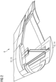
- Fig. 2 shows a wind turbine blade 6 of the wind turbine 1 of fig. 1 in a schematic perspective sectional view.
- the wind turbine blade 6 comprises two spar-caps 12, manufactured of carbon fibers and resin.
- an upper spar-cap 12 constitutes a first electrical path 13.
- a lower spar-cap 12 constitutes a second electrical path 14.
- FIG. 3 an alternative wind turbine blade 6 for the wind turbine 1 of fig. 1 is shown in a schematic exploded view.
- the root section 9, the intermediate section 11 and the tip end section 10 of the wind turbine blade 6 are illustrated.
- the first electrical path 13 is provided by a first electrical conductor 16.
- the first electrical conductor 16 is attached to a first wall 17 of the wind turbine blade 6.
- the second electrical path 14 is provided by a second electrical conductor 18.
- the second electrical conductor 18 is attached to a second wall 19 of the wind turbine blade 6.
- Fig. 4 shows a preferred embodiment of the method according to the invention in a schematic flowchart.
- a test signal for the first electrical path 13 is generated by the electrical time-domain reflectometry device 15.
- a first test signal response from the first electrical path 13 is received by the electrical time-domain reflectometry device 15.
- a second test signal response from the second electrical path 14 is received by the electrical time-domain reflectometry device 15.
- a strain of the wind turbine blade 6 is determined by the electrical time-domain reflectometry device 15 by analyzing the test signal responses.
Landscapes
- Engineering & Computer Science (AREA)
- Life Sciences & Earth Sciences (AREA)
- Sustainable Development (AREA)
- Sustainable Energy (AREA)
- Chemical & Material Sciences (AREA)
- Combustion & Propulsion (AREA)
- Mechanical Engineering (AREA)
- General Engineering & Computer Science (AREA)
- Wind Motors (AREA)
Priority Applications (5)
| Application Number | Priority Date | Filing Date | Title |
|---|---|---|---|
| DK23193682.4T DK4517085T3 (en) | 2023-08-28 | 2023-08-28 | Wind turbine with turbine blade strain control |
| EP23193682.4A EP4517085B1 (de) | 2023-08-28 | 2023-08-28 | Windturbine mit turbinenschaufelbelastungssteuerung |
| PCT/EP2024/071314 WO2025045475A1 (en) | 2023-08-28 | 2024-07-26 | Wind turbine with turbine blade strain control |
| CN202480055536.5A CN121752811A (zh) | 2023-08-28 | 2024-07-26 | 具有涡轮机叶片应变控制的风力涡轮机 |
| TW113132360A TWI903717B (zh) | 2023-08-28 | 2024-08-28 | 具有渦輪葉片應變控制的風力渦輪機 |
Applications Claiming Priority (1)
| Application Number | Priority Date | Filing Date | Title |
|---|---|---|---|
| EP23193682.4A EP4517085B1 (de) | 2023-08-28 | 2023-08-28 | Windturbine mit turbinenschaufelbelastungssteuerung |
Publications (2)
| Publication Number | Publication Date |
|---|---|
| EP4517085A1 true EP4517085A1 (de) | 2025-03-05 |
| EP4517085B1 EP4517085B1 (de) | 2025-10-08 |
Family
ID=87847958
Family Applications (1)
| Application Number | Title | Priority Date | Filing Date |
|---|---|---|---|
| EP23193682.4A Active EP4517085B1 (de) | 2023-08-28 | 2023-08-28 | Windturbine mit turbinenschaufelbelastungssteuerung |
Country Status (5)
| Country | Link |
|---|---|
| EP (1) | EP4517085B1 (de) |
| CN (1) | CN121752811A (de) |
| DK (1) | DK4517085T3 (de) |
| TW (1) | TWI903717B (de) |
| WO (1) | WO2025045475A1 (de) |
Citations (3)
| Publication number | Priority date | Publication date | Assignee | Title |
|---|---|---|---|---|
| US20170284376A1 (en) * | 2014-09-12 | 2017-10-05 | Robert Bosch Gmbh | Method and Control Device for Measuring a Load on a Rotor Blade of a Wind Power Plant |
| JP2021025859A (ja) * | 2019-08-02 | 2021-02-22 | 三菱重工業株式会社 | 断線検査方法 |
| EP4112928A1 (de) * | 2021-06-28 | 2023-01-04 | Siemens Gamesa Renewable Energy A/S | Blitzschutzsystembeurteilung auf basis von impedanzanalyse |
Family Cites Families (5)
| Publication number | Priority date | Publication date | Assignee | Title |
|---|---|---|---|---|
| WO2010086466A1 (es) * | 2009-01-30 | 2010-08-05 | Gamesa Innovation & Technology, S.L. | Sistema de medición de deformaciones en palas de aerogeneradores durante ensayos estáticos |
| KR101288493B1 (ko) * | 2011-11-14 | 2013-07-26 | 한국표준과학연구원 | 풍력발전 블레이드의 물리량 감지장치, 풍력발전 블레이드의 제어장치, 풍력발전 블레이드의 제어방법 |
| JP6320081B2 (ja) * | 2014-02-27 | 2018-05-09 | 三菱重工業株式会社 | 風車翼の損傷検知方法及び風車 |
| DE102016116138A1 (de) * | 2016-08-30 | 2018-03-01 | Wobben Properties Gmbh | Aktuatoreinrichtung für eine Windenergieanlage, Windenergieanlage und Montageverfahren |
| CN111075638B (zh) * | 2019-12-20 | 2021-01-12 | 南京航空航天大学 | 一种大型风力机叶片刚度改善装置 |
-
2023
- 2023-08-28 DK DK23193682.4T patent/DK4517085T3/da active
- 2023-08-28 EP EP23193682.4A patent/EP4517085B1/de active Active
-
2024
- 2024-07-26 WO PCT/EP2024/071314 patent/WO2025045475A1/en active Pending
- 2024-07-26 CN CN202480055536.5A patent/CN121752811A/zh active Pending
- 2024-08-28 TW TW113132360A patent/TWI903717B/zh active
Patent Citations (3)
| Publication number | Priority date | Publication date | Assignee | Title |
|---|---|---|---|---|
| US20170284376A1 (en) * | 2014-09-12 | 2017-10-05 | Robert Bosch Gmbh | Method and Control Device for Measuring a Load on a Rotor Blade of a Wind Power Plant |
| JP2021025859A (ja) * | 2019-08-02 | 2021-02-22 | 三菱重工業株式会社 | 断線検査方法 |
| EP4112928A1 (de) * | 2021-06-28 | 2023-01-04 | Siemens Gamesa Renewable Energy A/S | Blitzschutzsystembeurteilung auf basis von impedanzanalyse |
Also Published As
| Publication number | Publication date |
|---|---|
| TWI903717B (zh) | 2025-11-01 |
| CN121752811A (zh) | 2026-03-27 |
| DK4517085T3 (en) | 2025-12-01 |
| WO2025045475A1 (en) | 2025-03-06 |
| EP4517085B1 (de) | 2025-10-08 |
| TW202516108A (zh) | 2025-04-16 |
Similar Documents
| Publication | Publication Date | Title |
|---|---|---|
| CN112219029A (zh) | 用于风力涡轮机的传感器装置 | |
| DK2284393T3 (en) | LOAD RECORDING DEVICE FOR WIND MILL EXPERIENCES | |
| CN114109738B (zh) | 用于风力涡轮机叶片的监测系统、风力涡轮机布置以及用于监测风力涡轮机叶片的方法 | |
| DK2354543T3 (en) | Method of attaching a load sensor to a surface of a rotor vane and rotor vane | |
| TWI662187B (zh) | 風力發電用葉片或風力發電裝置 | |
| CN113404652A (zh) | 一种恶劣环境下风力发电机组叶片状态监测方法 | |
| JP6628395B2 (ja) | 外部雷保護システム、風車ブレード、及び風力発電装置 | |
| CN115126665B (zh) | 风力发电机的风机叶片监测方法及装置、存储介质、风力发电机 | |
| US20100135796A1 (en) | Monitoring joint efficiency in wind turbine rotor blades | |
| JP2023542378A (ja) | 風力タービン監視装置、風力タービンシステム、及び風力タービン監視方法 | |
| JP6778366B2 (ja) | ダブルダウンコンダクタシステム、ダブルダウンコンダクタシステムを用いた落雷判定システム、及び風力発電装置 | |
| US20120314201A1 (en) | Testing methods for wind turbine blades | |
| CN115977892A (zh) | 一种评估叶片疲劳寿命的方法、装置及叶片 | |
| CN116398379B (zh) | 基于分布式光纤传感的风电机组叶片状态监测装置及方法 | |
| EP4517085B1 (de) | Windturbine mit turbinenschaufelbelastungssteuerung | |
| CN107044388B (zh) | 风力发电机叶片健康状态监测系统及监测方法 | |
| US20240352922A1 (en) | Lightning protection system evaluation based on impedance analysis | |
| KR20140002782A (ko) | 풍력 발전 설비 | |
| JP6851053B2 (ja) | ダブルダウンコンダクタシステム、ダブルダウンコンダクタシステム用の健全性評価システム、及び風力発電装置 | |
| CN222596217U (zh) | 一种专用于海上风电机组的在线监测系统 | |
| CN211343230U (zh) | 海上风电机组多参量在线监测系统的轮毂数据采集通讯柜 | |
| EP3816437A1 (de) | Anordnung zur kalkulation der belastung eines windturbinenrotorblattes |
Legal Events
| Date | Code | Title | Description |
|---|---|---|---|
| PUAI | Public reference made under article 153(3) epc to a published international application that has entered the european phase |
Free format text: ORIGINAL CODE: 0009012 |
|
| STAA | Information on the status of an ep patent application or granted ep patent |
Free format text: STATUS: REQUEST FOR EXAMINATION WAS MADE |
|
| 17P | Request for examination filed |
Effective date: 20240423 |
|
| AK | Designated contracting states |
Kind code of ref document: A1 Designated state(s): AL AT BE BG CH CY CZ DE DK EE ES FI FR GB GR HR HU IE IS IT LI LT LU LV MC ME MK MT NL NO PL PT RO RS SE SI SK SM TR |
|
| GRAP | Despatch of communication of intention to grant a patent |
Free format text: ORIGINAL CODE: EPIDOSNIGR1 |
|
| STAA | Information on the status of an ep patent application or granted ep patent |
Free format text: STATUS: GRANT OF PATENT IS INTENDED |
|
| INTG | Intention to grant announced |
Effective date: 20250401 |
|
| GRAS | Grant fee paid |
Free format text: ORIGINAL CODE: EPIDOSNIGR3 |
|
| GRAA | (expected) grant |
Free format text: ORIGINAL CODE: 0009210 |
|
| STAA | Information on the status of an ep patent application or granted ep patent |
Free format text: STATUS: THE PATENT HAS BEEN GRANTED |
|
| AK | Designated contracting states |
Kind code of ref document: B1 Designated state(s): AL AT BE BG CH CY CZ DE DK EE ES FI FR GB GR HR HU IE IS IT LI LT LU LV MC ME MK MT NL NO PL PT RO RS SE SI SK SM TR |
|
| REG | Reference to a national code |
Ref country code: GB Ref legal event code: FG4D Ref country code: CH Ref legal event code: F10 Free format text: ST27 STATUS EVENT CODE: U-0-0-F10-F00 (AS PROVIDED BY THE NATIONAL OFFICE) Effective date: 20251008 |
|
| REG | Reference to a national code |
Ref country code: DE Ref legal event code: R096 Ref document number: 602023007284 Country of ref document: DE |
|
| REG | Reference to a national code |
Ref country code: IE Ref legal event code: FG4D |
|
| REG | Reference to a national code |
Ref country code: DK Ref legal event code: T3 Effective date: 20251127 |
|
| REG | Reference to a national code |
Ref country code: NL Ref legal event code: MP Effective date: 20251008 |
|
| REG | Reference to a national code |
Ref country code: AT Ref legal event code: MK05 Ref document number: 1844989 Country of ref document: AT Kind code of ref document: T Effective date: 20251008 |
|
| PG25 | Lapsed in a contracting state [announced via postgrant information from national office to epo] |
Ref country code: NL Free format text: LAPSE BECAUSE OF FAILURE TO SUBMIT A TRANSLATION OF THE DESCRIPTION OR TO PAY THE FEE WITHIN THE PRESCRIBED TIME-LIMIT Effective date: 20251008 |
|
| PG25 | Lapsed in a contracting state [announced via postgrant information from national office to epo] |
Ref country code: ES Free format text: LAPSE BECAUSE OF FAILURE TO SUBMIT A TRANSLATION OF THE DESCRIPTION OR TO PAY THE FEE WITHIN THE PRESCRIBED TIME-LIMIT Effective date: 20251008 |
|
| REG | Reference to a national code |
Ref country code: LT Ref legal event code: MG9D |
|
| PG25 | Lapsed in a contracting state [announced via postgrant information from national office to epo] |
Ref country code: NO Free format text: LAPSE BECAUSE OF FAILURE TO SUBMIT A TRANSLATION OF THE DESCRIPTION OR TO PAY THE FEE WITHIN THE PRESCRIBED TIME-LIMIT Effective date: 20260108 |
|
| PG25 | Lapsed in a contracting state [announced via postgrant information from national office to epo] |
Ref country code: HR Free format text: LAPSE BECAUSE OF FAILURE TO SUBMIT A TRANSLATION OF THE DESCRIPTION OR TO PAY THE FEE WITHIN THE PRESCRIBED TIME-LIMIT Effective date: 20251008 Ref country code: FI Free format text: LAPSE BECAUSE OF FAILURE TO SUBMIT A TRANSLATION OF THE DESCRIPTION OR TO PAY THE FEE WITHIN THE PRESCRIBED TIME-LIMIT Effective date: 20251008 Ref country code: AT Free format text: LAPSE BECAUSE OF FAILURE TO SUBMIT A TRANSLATION OF THE DESCRIPTION OR TO PAY THE FEE WITHIN THE PRESCRIBED TIME-LIMIT Effective date: 20251008 |
|
| PG25 | Lapsed in a contracting state [announced via postgrant information from national office to epo] |
Ref country code: RS Free format text: LAPSE BECAUSE OF FAILURE TO SUBMIT A TRANSLATION OF THE DESCRIPTION OR TO PAY THE FEE WITHIN THE PRESCRIBED TIME-LIMIT Effective date: 20260108 |
|
| PG25 | Lapsed in a contracting state [announced via postgrant information from national office to epo] |
Ref country code: IS Free format text: LAPSE BECAUSE OF FAILURE TO SUBMIT A TRANSLATION OF THE DESCRIPTION OR TO PAY THE FEE WITHIN THE PRESCRIBED TIME-LIMIT Effective date: 20260208 |
|
| PG25 | Lapsed in a contracting state [announced via postgrant information from national office to epo] |
Ref country code: PT Free format text: LAPSE BECAUSE OF FAILURE TO SUBMIT A TRANSLATION OF THE DESCRIPTION OR TO PAY THE FEE WITHIN THE PRESCRIBED TIME-LIMIT Effective date: 20260209 |
|
| PG25 | Lapsed in a contracting state [announced via postgrant information from national office to epo] |
Ref country code: PL Free format text: LAPSE BECAUSE OF FAILURE TO SUBMIT A TRANSLATION OF THE DESCRIPTION OR TO PAY THE FEE WITHIN THE PRESCRIBED TIME-LIMIT Effective date: 20251008 |
|
| PG25 | Lapsed in a contracting state [announced via postgrant information from national office to epo] |
Ref country code: LV Free format text: LAPSE BECAUSE OF FAILURE TO SUBMIT A TRANSLATION OF THE DESCRIPTION OR TO PAY THE FEE WITHIN THE PRESCRIBED TIME-LIMIT Effective date: 20251008 |