EP4517111A1 - Module de découplage - Google Patents
Module de découplage Download PDFInfo
- Publication number
- EP4517111A1 EP4517111A1 EP23193956.2A EP23193956A EP4517111A1 EP 4517111 A1 EP4517111 A1 EP 4517111A1 EP 23193956 A EP23193956 A EP 23193956A EP 4517111 A1 EP4517111 A1 EP 4517111A1
- Authority
- EP
- European Patent Office
- Prior art keywords
- module
- locking
- module housing
- decoupling
- locking unit
- Prior art date
- Legal status (The legal status is an assumption and is not a legal conclusion. Google has not performed a legal analysis and makes no representation as to the accuracy of the status listed.)
- Pending
Links
Images




Classifications
-
- F—MECHANICAL ENGINEERING; LIGHTING; HEATING; WEAPONS; BLASTING
- F15—FLUID-PRESSURE ACTUATORS; HYDRAULICS OR PNEUMATICS IN GENERAL
- F15B—SYSTEMS ACTING BY MEANS OF FLUIDS IN GENERAL; FLUID-PRESSURE ACTUATORS, e.g. SERVOMOTORS; DETAILS OF FLUID-PRESSURE SYSTEMS, NOT OTHERWISE PROVIDED FOR
- F15B15/00—Fluid-actuated devices for displacing a member from one position to another; Gearing associated therewith
- F15B15/19—Pyrotechnical actuators
-
- B—PERFORMING OPERATIONS; TRANSPORTING
- B60—VEHICLES IN GENERAL
- B60N—SEATS SPECIALLY ADAPTED FOR VEHICLES; VEHICLE PASSENGER ACCOMMODATION NOT OTHERWISE PROVIDED FOR
- B60N2/00—Seats specially adapted for vehicles; Arrangement or mounting of seats in vehicles
- B60N2/24—Seats specially adapted for vehicles; Arrangement or mounting of seats in vehicles for particular purposes or particular vehicles
- B60N2/42—Seats specially adapted for vehicles; Arrangement or mounting of seats in vehicles for particular purposes or particular vehicles the seat constructed to protect the occupant from the effect of abnormal g-forces, e.g. crash or safety seats
- B60N2/427—Seats or parts thereof displaced during a crash
- B60N2/42772—Seats or parts thereof displaced during a crash characterised by the triggering system
- B60N2/42781—Seats or parts thereof displaced during a crash characterised by the triggering system mechanical triggering
-
- B—PERFORMING OPERATIONS; TRANSPORTING
- B60—VEHICLES IN GENERAL
- B60N—SEATS SPECIALLY ADAPTED FOR VEHICLES; VEHICLE PASSENGER ACCOMMODATION NOT OTHERWISE PROVIDED FOR
- B60N2/00—Seats specially adapted for vehicles; Arrangement or mounting of seats in vehicles
- B60N2/24—Seats specially adapted for vehicles; Arrangement or mounting of seats in vehicles for particular purposes or particular vehicles
- B60N2/42—Seats specially adapted for vehicles; Arrangement or mounting of seats in vehicles for particular purposes or particular vehicles the seat constructed to protect the occupant from the effect of abnormal g-forces, e.g. crash or safety seats
- B60N2/427—Seats or parts thereof displaced during a crash
- B60N2/42727—Seats or parts thereof displaced during a crash involving substantially rigid displacement
- B60N2/42736—Seats or parts thereof displaced during a crash involving substantially rigid displacement of the whole seat
-
- B—PERFORMING OPERATIONS; TRANSPORTING
- B60—VEHICLES IN GENERAL
- B60N—SEATS SPECIALLY ADAPTED FOR VEHICLES; VEHICLE PASSENGER ACCOMMODATION NOT OTHERWISE PROVIDED FOR
- B60N2/00—Seats specially adapted for vehicles; Arrangement or mounting of seats in vehicles
- B60N2/02—Seats specially adapted for vehicles; Arrangement or mounting of seats in vehicles the seat or part thereof being movable, e.g. adjustable
- B60N2/04—Seats specially adapted for vehicles; Arrangement or mounting of seats in vehicles the seat or part thereof being movable, e.g. adjustable the whole seat being movable
- B60N2/06—Seats specially adapted for vehicles; Arrangement or mounting of seats in vehicles the seat or part thereof being movable, e.g. adjustable the whole seat being movable slidable
- B60N2/08—Seats specially adapted for vehicles; Arrangement or mounting of seats in vehicles the seat or part thereof being movable, e.g. adjustable the whole seat being movable slidable characterised by the locking device
-
- B—PERFORMING OPERATIONS; TRANSPORTING
- B60—VEHICLES IN GENERAL
- B60N—SEATS SPECIALLY ADAPTED FOR VEHICLES; VEHICLE PASSENGER ACCOMMODATION NOT OTHERWISE PROVIDED FOR
- B60N2/00—Seats specially adapted for vehicles; Arrangement or mounting of seats in vehicles
- B60N2/24—Seats specially adapted for vehicles; Arrangement or mounting of seats in vehicles for particular purposes or particular vehicles
- B60N2/42—Seats specially adapted for vehicles; Arrangement or mounting of seats in vehicles for particular purposes or particular vehicles the seat constructed to protect the occupant from the effect of abnormal g-forces, e.g. crash or safety seats
- B60N2/4207—Seats specially adapted for vehicles; Arrangement or mounting of seats in vehicles for particular purposes or particular vehicles the seat constructed to protect the occupant from the effect of abnormal g-forces, e.g. crash or safety seats characterised by the direction of the g-forces
- B60N2/4214—Seats specially adapted for vehicles; Arrangement or mounting of seats in vehicles for particular purposes or particular vehicles the seat constructed to protect the occupant from the effect of abnormal g-forces, e.g. crash or safety seats characterised by the direction of the g-forces longitudinal
-
- B—PERFORMING OPERATIONS; TRANSPORTING
- B60—VEHICLES IN GENERAL
- B60N—SEATS SPECIALLY ADAPTED FOR VEHICLES; VEHICLE PASSENGER ACCOMMODATION NOT OTHERWISE PROVIDED FOR
- B60N2/00—Seats specially adapted for vehicles; Arrangement or mounting of seats in vehicles
- B60N2/24—Seats specially adapted for vehicles; Arrangement or mounting of seats in vehicles for particular purposes or particular vehicles
- B60N2/42—Seats specially adapted for vehicles; Arrangement or mounting of seats in vehicles for particular purposes or particular vehicles the seat constructed to protect the occupant from the effect of abnormal g-forces, e.g. crash or safety seats
- B60N2/43—Safety locks
-
- F—MECHANICAL ENGINEERING; LIGHTING; HEATING; WEAPONS; BLASTING
- F42—AMMUNITION; BLASTING
- F42B—EXPLOSIVE CHARGES, e.g. FOR BLASTING, FIREWORKS, AMMUNITION
- F42B3/00—Blasting cartridges, i.e. case and explosive
- F42B3/006—Explosive bolts; Explosive actuators
-
- B—PERFORMING OPERATIONS; TRANSPORTING
- B60—VEHICLES IN GENERAL
- B60N—SEATS SPECIALLY ADAPTED FOR VEHICLES; VEHICLE PASSENGER ACCOMMODATION NOT OTHERWISE PROVIDED FOR
- B60N2/00—Seats specially adapted for vehicles; Arrangement or mounting of seats in vehicles
- B60N2/24—Seats specially adapted for vehicles; Arrangement or mounting of seats in vehicles for particular purposes or particular vehicles
- B60N2/42—Seats specially adapted for vehicles; Arrangement or mounting of seats in vehicles for particular purposes or particular vehicles the seat constructed to protect the occupant from the effect of abnormal g-forces, e.g. crash or safety seats
- B60N2/427—Seats or parts thereof displaced during a crash
-
- B—PERFORMING OPERATIONS; TRANSPORTING
- B60—VEHICLES IN GENERAL
- B60N—SEATS SPECIALLY ADAPTED FOR VEHICLES; VEHICLE PASSENGER ACCOMMODATION NOT OTHERWISE PROVIDED FOR
- B60N2/00—Seats specially adapted for vehicles; Arrangement or mounting of seats in vehicles
- B60N2/24—Seats specially adapted for vehicles; Arrangement or mounting of seats in vehicles for particular purposes or particular vehicles
- B60N2/42—Seats specially adapted for vehicles; Arrangement or mounting of seats in vehicles for particular purposes or particular vehicles the seat constructed to protect the occupant from the effect of abnormal g-forces, e.g. crash or safety seats
- B60N2/427—Seats or parts thereof displaced during a crash
- B60N2/42772—Seats or parts thereof displaced during a crash characterised by the triggering system
- B60N2/4279—Seats or parts thereof displaced during a crash characterised by the triggering system electric or electronic triggering
-
- F—MECHANICAL ENGINEERING; LIGHTING; HEATING; WEAPONS; BLASTING
- F16—ENGINEERING ELEMENTS AND UNITS; GENERAL MEASURES FOR PRODUCING AND MAINTAINING EFFECTIVE FUNCTIONING OF MACHINES OR INSTALLATIONS; THERMAL INSULATION IN GENERAL
- F16B—DEVICES FOR FASTENING OR SECURING CONSTRUCTIONAL ELEMENTS OR MACHINE PARTS TOGETHER, e.g. NAILS, BOLTS, CIRCLIPS, CLAMPS, CLIPS OR WEDGES; JOINTS OR JOINTING
- F16B19/00—Bolts without screw-thread; Pins, including deformable elements; Rivets
- F16B19/02—Bolts or sleeves for positioning of machine parts, e.g. notched taper pins, fitting pins, sleeves, eccentric positioning rings
Definitions
- the invention relates to a decoupling module for two detachably connected components and to a vehicle seat with such a decoupling module.
- the invention is based on the object of improving a decoupling module of the type mentioned at the outset, which in particular also decouples under load, and of providing a corresponding vehicle seat with such an improved decoupling module.
- the first-mentioned object is achieved according to the invention by a decoupling module with the features of claim 1.
- the second-mentioned object is solved according to the invention by a vehicle seat with the features of claim 10.
- the decoupling module according to the invention for two components that are detachably connected to one another comprises at least one module housing with a coupling interface, in particular an external first one, in particular for coupling to one of the components, and a cavity, a locking unit that is mounted axially movably in the module housing on the one hand and protrudes at least partially from the module housing in an initial state, in particular in order to detachably lock or couple the two components to one another, and a drive unit that is arranged in a fixed position in the module housing on the other hand, wherein the locking unit and the drive unit are designed to interact in such a way that when the drive unit is triggered or ignited, the locking unit can be or is suddenly directly acted upon by a pressure surge spreading or building up in the cavity and moves into the module housing.
- the locking unit is axially movable along a linear axis and moves linearly into the module housing.
- the decoupling module is designed with the locking unit and the drive unit, which interact with each other, as a linear locking release, in particular a linear bolt release or a linear latch release.
- the spreading pressure surge or a building up integral pressure can be generated, for example, by a gas or gas mixture of the drive unit introduced into the cavity.
- the cavity is also referred to as the gas space. Because the pressure surge is applied directly to the locking unit, a particularly compact decoupling module with a high working force and a high working pressure is possible.
- the module housing, locking unit and drive unit can be arranged coaxially to one another, for example.
- the module housing, locking unit and drive unit can each be oriented and arranged coaxially to their longitudinal axes.
- the module housing has a cavity, in particular a cup-shaped cavity, in which the locking unit and the drive unit are arranged coaxially to one another.
- the module housing, the locking unit and the drive unit can each be arranged at least partially overlapping and coaxially to one another, for example.
- the coaxial arrangement of the components of the decoupling module enables simple production and a simple, modular and particularly compact structure of the decoupling module.
- the drive unit can be designed, for example, as a pyrotechnic device.
- the drive unit can be supported, in particular, via its front sides on the one hand on the module housing and on the other hand on the locking unit.
- the decoupling module in particular the module housing, for example the module cover, can furthermore have a second, for example external, coupling interface.
- the first coupling interface of the module housing can be designed as an external thread, for example.
- the second coupling interface of the module housing can be designed as a nut, in particular a hexagon profile or a hexagon nut, for example. This allows the decoupling module to be easily attached to one of the two components to be connected without tools using only one coupling interface. or with a wrench for two coupling interfaces.
- an axial end of the drive unit can be designed as a module cover which is positively and/or non-positively connected to the module housing when the decoupling module is in the assembled state.
- the module cover can be crimped, screwed or the like to the module housing.
- the module housing and the drive unit can be connected to one another in such a way that they are sealed gas-tight to the outside when assembled.
- the module housing can in particular be sealed gas-tight to the outside in such a way that when the drive unit is triggered, the locking unit is held or is held in the retracted position at least temporarily.
- the locking unit can be designed to be lockable in the retracted position.
- the module cover can be arranged to partially overlap the module housing.
- the module housing and the module cover can be telescopically inserted into one another.
- the module cover can be partially slipped over an outer wall of the module housing.
- an outer wall of the module housing can be partially slipped over the module cover.
- the locking unit can, for example, comprise a locking section and a pressure application section which can be subjected to the pressure surge when the drive unit is triggered or ignited, so that the locking unit moves into the module housing at an accelerated rate and decouples the two components from each other.
- the location of the force application on the locking unit can be designed variably, in particular with regard to geometric shape, orientation and arrangement of the locking unit relative to the drive unit and can be influenced by these parameters.
- the pressure-acting section can be designed, for example, as a cylindrical hollow chamber or cup-shaped hollow chamber with at least one recess.
- the at least one recess can be designed, for example, as a gas passage, a through-flow opening, an overflow opening, an overflow channel or the like.
- the pressure-acting section can comprise several recesses that are distributed symmetrically.
- the locking section can be designed, for example, as a shaft end, a latch, a pin or another suitable locking element.
- the locking element can be pre-tensioned in a connected state of the two components by means of a force accumulator, in particular a spring element, for lockingly connecting the two components.
- the module housing can furthermore have an opening, for example in a housing base for a shaft end of the locking unit, through which the shaft end protrudes at least partially from the module housing in the connected state in order to connect the two components to one another in a locked manner or to keep them locked to one another.
- the vehicle seat according to the invention comprises the decoupling module described above.
- the invention provides an axisymmetric decoupling module.
- the axially symmetrical decoupling module has, on the one hand, the first coupling interface of the module housing designed as a screw thread with an opening for the locking unit designed as a pin, pin or shaft end and, on the other hand, the second coupling interface designed, for example, as a hexagon or nut.
- Such a decoupling module with at least one of the coupling interfaces allows this decoupling module to be easily screwed into one of the components.
- a in the Figure 1 The schematically illustrated vehicle seat 100 is subsequently produced using three perpendicular Spatial directions are described.
- a longitudinal direction x runs largely horizontally and preferably parallel to a vehicle longitudinal direction that corresponds to the normal direction of travel of the vehicle.
- a transverse direction y running perpendicular to the longitudinal direction x is also aligned horizontally in the vehicle and runs parallel to a vehicle transverse direction.
- a vertical direction z runs perpendicular to the longitudinal direction x and perpendicular to the transverse direction y.
- the vertical direction z preferably runs parallel to a vehicle vertical axis.
- the position and direction information used refer to a viewing direction of an occupant sitting in the vehicle seat 100 in a normal sitting position, with the vehicle seat 100 installed in the vehicle, in a position of use suitable for transporting people with the backrest 104 upright and aligned in the direction of travel as usual.
- the vehicle seat 100 can also be installed or moved in a different orientation, for example transversely to the direction of travel.
- the vehicle seat 100 is constructed mirror-symmetrically to a plane running perpendicular to the transverse direction y.
- the backrest 104 can be pivotably arranged on a seat part 102 of the vehicle seat 100.
- the vehicle seat 100 can optionally comprise a fitting 106, in particular an adjustment fitting, rotary fitting, locking fitting or wobble fitting.
- the position and direction information used such as radial, axial and circumferential, refer to a rotation axis 108 of the fitting 106.
- Radial means perpendicular to the rotation axis 108.
- Axial means in the direction or parallel to the rotation axis 108.
- the vehicle seat 100 can optionally comprise a longitudinal adjustment device 110.
- the longitudinal adjustment device 110 comprises, for example, a rail arrangement 112 with a first rail element 114 and a second rail element 116.
- the first rail element 114 is adjustable in the longitudinal direction x relative to the second rail element 116.
- the first rail element 114 is fastened to the seat part 102.
- the second rail element 116 is fastened to a structural element of a vehicle, for example a vehicle floor.
- the first rail element 114 is referred to as the upper rail 114 in the following description.
- This upper rail 114 also called a running rail or slide
- the second rail element 116 is referred to below as the lower rail 116.
- the lower rail 116 is fixed and is connected, for example, to the floor of a vehicle.
- a decoupling module 200 can be provided for the sudden decoupler, for example, of components of the vehicle seat 100, in particular of components of the longitudinal adjustment device 110, in the event of a collision.
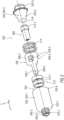
- Figure 2 shows an exploded view of a decoupling module 200 according to the invention according to a first embodiment.
- the decoupling module 200 comprises at least one module housing 202.
- the module housing 202 is designed as a hollow body.
- the module housing 202 has a cavity 204.
- the cavity 204 is in particular hollow-cylindrical or cup-shaped.
- the module housing 202 can be modular.
- the module housing 202 can have a
- the module housing 202 further comprises a first coupling interface 202.3.
- the first coupling interface 202.3 is an external interface for coupling to one of the two components, which can be or are locked together releasably by means of the decoupling module 200.
- the first coupling interface 202.3 is designed, for example, as an external thread.
- the first coupling interface 202.3 is designed, for example, as an external thread on the outside of a first front end 202.4.
- the decoupling module 200 can thus be easily screwed into or onto one of the two components.
- the decoupling module 200 further comprises a locking unit 206 and a drive unit 208.
- the locking unit 206 is mounted axially movably in the module housing 202. In an initial state, the locking unit 206 protrudes at least partially from the module housing 202, in particular in order to detachably lock or couple the two components together, as in Figure 4 shown.
- the drive unit 208 is arranged stationary in the module housing 202.
- the locking unit 206 and the drive unit 208 are designed to interact in such a way that when the drive unit 208 is triggered or ignited, the locking unit 206 can be or is suddenly directly acted upon by a pressure surge spreading or building up in the cavity 204 and moves into the module housing 202.
- the locking unit 206 is axially movable along a linear axis 210 and moves linearly into the module housing 202 when the locking unit 208 is triggered.
- the decoupling module 200 is designed with the locking unit 206 and the drive unit 208, which interact with each other, as a linear locking trigger, in particular a linear bolt trigger or a linear latch trigger.
- the drive unit 208 can be designed, for example, as a pyrotechnic device, for example a gas generator with a pyrotechnic igniter.
- the drive unit 208 can be supported, in particular via its end faces, on the one hand on the module housing 202, in particular on the module cover 202.2, and on the other hand on the locking unit 206.
- the module cover 202.2 can have a receptacle 202.9 for the drive unit 208 protruding in the direction of the module base body 202.1.
- the module housing 202 and the drive unit 208 can be connected to one another in such a way that they are sealed gas-tight to the outside when assembled.
- at least one seal 212 can be provided.
- the seal 212 comprises, for example, two first sealing rings 212.1, which are arranged between the locking unit 206 and the module housing 202.
- the seal 212 can, for example, additionally or alternatively be designed as a second sealing ring 212.2, which is arranged on the outside of the drive unit 208 and seals the module cover 202.2 to the outside.
- the locking unit 206 can, for example, comprise a locking section 206.1 and a pressure application section 206.2, which can be subjected to the pressure surge when the drive unit 208 is triggered or ignited, so that the locking unit 206 moves into the module housing 202 at an accelerated rate and decouples the two components from one another.
- the location of the force acting on the locking unit 206, in particular on the pressure application section 206.2, can be variable, in particular with regard to the geometric shape, orientation and arrangement of the locking unit 206 relative to the drive unit 208, and can be influenced by these parameters.
- the pressure application section 206.2 can be designed, for example, as a cylindrical hollow chamber or cup-shaped hollow chamber with at least one Recess 206.3 can be formed.
- the at least one recess 206.3 can be formed, for example, as a gas passage 206.4.
- the recess 206.3 can be formed as a through-flow opening, an overflow opening or the like.
- the pressure-acting section 206.2 can comprise several recesses 206.3 that are distributed symmetrically.
- the locking section 206.1 can be designed, for example, as a shaft end 206.5. Alternatively, the locking section 206.1 can be designed as a latch, a pin or another suitable locking element.
- the locking section 206.1 can be pre-tensioned in a connected state of the two components by means of a force accumulator 214, in particular a spring element, in particular a helical spring, for lockingly connecting the two components.
- the module housing 202 can furthermore have an opening 202.8, for example in a housing base 202.7 for a shaft end 206.5 of the locking unit 206, in particular for a bolt-shaped or pin-shaped shaft end 206.5, through which the shaft end 206.5 protrudes at least partially from the module housing 202 in the connected state in order to connect the two components to one another in a locked manner or to keep them locked to one another.
- an opening 202.8 for example in a housing base 202.7 for a shaft end 206.5 of the locking unit 206, in particular for a bolt-shaped or pin-shaped shaft end 206.5, through which the shaft end 206.5 protrudes at least partially from the module housing 202 in the connected state in order to connect the two components to one another in a locked manner or to keep them locked to one another.
- Figure 3 shows a perspective and partially cutaway view of the decoupling module 200 of the first embodiment in the assembled state.
- the module cover 202.2 can be arranged partially overlapping with the module base body 202.1.
- the module base body 202.1 and the module cover 202.2 can be telescopically inserted into one another.
- an outer wall of the module base body 202.1 can be partially placed over the module cover 202.2.
- the receptacle 202.9 of the module cover 202.2 is designed on the inside to correspond to an external shape and/or external dimensions of the drive unit 208. On the outside, the receptacle 202.9 is designed in such a way that the energy accumulator 214 can be supported.
- the receptacle 202.9 has at least one shoulder 202.10 on the outside.
- the receptacle 202.9 can have a groove 202.11 for the second sealing ring 212.2.
- the module cover 202.2 can have a fastening flange 202.12, which is arranged in a form-fitting and/or force-fitting manner in a fastening groove 202.13 of the module base body 202.1.
- the drive unit 208 When the drive unit 208 is ignited, it generates a pressure surge or an integral pressure through a gas 216 or gas mixture introduced into the cavity 204.
- the cavity 204 is also referred to as the gas space.
- the pressure-acting section 206.2 of the locking unit 206 is subjected to the gas 216. The fact that the pressure surge acts directly on the locking unit 206 enables a particularly compact decoupling module 200 with a high working force and a high working pressure.
- the locking unit 206 moves linearly into the module housing 202 as a result of the applied pressure surge and forms a linear bolt release or a linear latch release.
- the module housing 202, the locking unit 206 and the drive unit 208 can be arranged coaxially to one another.
- the module housing 202, locking unit 206 and drive unit 208 are each oriented and arranged coaxially to their longitudinal axes and the linear axis 210.
- module housing 202 the locking unit 206 and the drive unit 208 can, for example, each be arranged at least partially overlapping and coaxial with each other.
- Figure 4 shows a perspective view of the decoupling module 200 of the first embodiment in the assembled state.
- the energy accumulator 214 is supported on the one hand on the shoulder 202.10 of the module cover 202.2 and on the other hand on a front end of the pressure application section 206.2 of the locking unit 206.
- the fastening flange 202.12 of the module cover 202.2 can additionally be provided with an anti-twist device 202.14.
- the anti-twist device 202.14 can be formed, for example, from at least one radially protruding rib and a corresponding slot on an inner side of the module base body 202.1. In the assembled state, the rib engages in the slot in a rotationally fixed manner. This can assist in screwing the decoupling module 200 into one of the components, in particular an internal thread, via the first coupling interface 202.3, in particular an external thread, by means of a tool engaging in the second coupling interface 202.5, in particular a hexagon or a nut element.
- Figure 5 shows a perspective view of the module cover 202.2 with the drive unit 208, which are pre-assembled together.
- the module cover 202.2 has a connection opening 202.15 for the drive unit 208 at its front end.
- a connection unit 208.1 for connecting electrical cables and/or ignition cables protrudes into 202.15.
- the connection unit 208.1 is arranged in the connection opening 202.15 and is freely accessible from the outside.
- the anti-twisting device 202.14 can have a plurality of ribs that are symmetrically distributed below the mounting flange 202.12.
- Figure 6 shows a perspective view of the locking unit 206.
- the locking unit 206 has the locking section 206.1 with the shaft end 206.5, which connects the two components to one another in a locking manner (not shown), and the pressure-acting section 206.2 with the recesses 206.3, which are designed as a gas passage 206.4.
- the pressure application section 206.2 is cup-shaped and comprises a number of alternately arranged separating webs 206.6 and recesses 206.3.
- Figure 7 shows an exploded view of a decoupling module 300 according to the invention according to a second embodiment.
- the decoupling module 300 differs from the decoupling module 200 only in the shape of the locking unit 306 and the module housing 302. All other structural features and functions of the decoupling module 300 are analogous to the decoupling module 200, as previously described.
- the decoupling module 300 has as recesses 306.3 gas channels 306.4.
- the gas channels 306.4 can be arranged, for example, on an outer side of the inwardly projecting receptacle 302.9 of the module housing 302. Alternatively or additionally, gas channels 306.4 can be formed on an inner side of the hollow cylindrical pressure-acting section 306.2 of the locking unit 306.
- the locking section 306.1 protrudes from the pressure application section 306.2 in the direction of the module base body 302.1.
- the decoupling module 300 is sealed gas-tight to the outside.
- the drive unit 308 is arranged and held in the module cover 302.2 in a similar manner in a stationary manner, in particular in a form-fitting and/or force-fitting manner.
- Figure 8 shows an exploded view of a decoupling module according to the invention according to a third embodiment and Figure 9 shows the decoupling module 400 after Figure 8 in assembled state.
- the decoupling module 400 differs from the decoupling module 200 or 300 only in the structure of the locking unit 306. All other structural features and functions of the decoupling module 400 are analogous to the decoupling module 200 or 300, as previously described.
- the locking unit 406 of the decoupling module 400 is designed in several parts.
- the locking unit 406 comprises a separate locking section 406.1, which is designed as a separate pin or stud.
- the pressure application section 406.2 is also designed separately.
- the Pressure device section 406.2 is designed as an inner hollow cylinder or inner cylindrical housing.
- the pin-shaped or pin-shaped locking section 406.1 can be inserted into the pressure-acting section 406.2.
- the locking section 406.1 has such a shape and/or such dimensions that, when inserted in the pressure-acting section 406.2, it protrudes through an opening 406.3 and protrudes in the direction of the module base body 402.1 of the module housing 402 and protrudes through a housing opening 402.3 aligned with the opening 406.3 and protrudes outward from the module base body 402.1.
- the module base body 402.1 is a hollow cylinder and forms an outer section of the module housing 402.
- the module base body 402.1 can be closed with the module cover 402.2 on the side opposite to the housing opening 402.3.
- Two seals 412 designed as sealing rings 412.1 are provided to seal the module housing 402.
- the decoupling module 400 is sealed gas-tight to the outside by means of the seal 412 designed as sealing rings 412.1.
- the drive unit 408 is arranged and held in the module cover 402.2 in a similar manner in a stationary manner, in particular in a form-fitting and/or force-fitting manner.
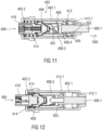
- the locking section 406.1 can be mounted in a connected state of the two components by means of a force accumulator 414, in particular a spring element, in particular a helical spring, for lockingly connecting the two components in a pre-tensioned manner in the module base body 402.1, as in Figures 11 and 12 shown.
- a force accumulator 414 in particular a spring element, in particular a helical spring
- the decoupling module 400 can also comprise, for example, an elongated connection element 416.
- the connection element 416 is designed as an interface or adapter for connecting lines or cables to the drive unit 408.
- Figure 9 shows a perspective view of the decoupling module 400 according to Figure 8 in the assembled state with the outer module cover 402.2, the outer module base body 402.1 and the pin-shaped or pin-shaped locking section 406.1 of the locking unit 406 protruding therefrom.
- FIG 10 shows schematically in perspective the multi-part locking unit 406 in the assembled state.
- the multi-part locking unit 406 comprises the pin-shaped locking section 406.1 and the cylindrical pressure-acting section 406.2.
- the pressure-acting section 406.2 comprises instead of the recesses 206.3 of the decoupling module 200 designed as gas passages 206.4
- Gas channels 406.4 designed as recesses in an analogous manner to the gas channels 306.4 of the decoupling module 300 according to Figure 7 .
- the gas channels 406.4 can, for example, be formed on an inner side of the hollow cylindrical pressure-acting section 406.2 of the locking unit 406.
- Figure 11 shows schematically in section the decoupling module 400 according to Figure 9 before or when the drive unit 408 is triggered.
- the energy accumulator 414 is in the relaxed state or partially relaxed state and holds or presses the locking unit 406 in the locking direction 500 against the seal 412 in the module housing 402.
- a pressure surge is generated against the locking section 406.1 by a gas or gas mixture introduced into the cavity 404 through the gas channels 406.4 according to arrows 502, in particular into the cavity 404 sealed to the outside by means of the sealing rings 412.1.
- the pressure-acting section 406.2 is provided with the gas channels 406.4 in the direction of the cavity 404, which Figure 10 are shown.
- Figure 12 shows schematically in section the decoupling module 400 according to Figures 9 and 10 after the drive unit 408 has been triggered and in the unlocked state.
- Figure 13 shows a schematic perspective view of another decoupling module 600 in the assembled state with a crimped module housing 602. All of the previously described screwed module housings 202, 302 and 402 can have a crimped or crimpable module housing 202, 302 or 402 instead of the respective module cover 202.2, 302.2 and 402.2, which can be screwed or is screwed to the associated module base body 202.1, 302.1 and 402.1.
- the respective module housing 202, 302 and 402 can be arranged analogously to the module housing 602 according to Figure 13
- the module housing 602 is designed such that it can be plastically deformed, in particular squeezed, flanged or folded, by means of a crimp band 602.4 and can be tightly closed to the outside.
Landscapes
- Engineering & Computer Science (AREA)
- Mechanical Engineering (AREA)
- Aviation & Aerospace Engineering (AREA)
- Transportation (AREA)
- General Engineering & Computer Science (AREA)
- Chemical & Material Sciences (AREA)
- Analytical Chemistry (AREA)
- Physics & Mathematics (AREA)
- Fluid Mechanics (AREA)
- Air Bags (AREA)
- Connection Of Plates (AREA)
Priority Applications (5)
| Application Number | Priority Date | Filing Date | Title |
|---|---|---|---|
| EP23193956.2A EP4517111A1 (fr) | 2023-08-29 | 2023-08-29 | Module de découplage |
| PCT/EP2024/073208 WO2025045627A1 (fr) | 2023-08-29 | 2024-08-19 | Module de découplage |
| KR1020267006131A KR20260044969A (ko) | 2023-08-29 | 2024-08-19 | 디커플링 모듈 |
| US18/818,667 US20250074272A1 (en) | 2023-08-29 | 2024-08-29 | Decoupling module |
| CN202411198620.0A CN119527140A (zh) | 2023-08-29 | 2024-08-29 | 解耦模块 |
Applications Claiming Priority (1)
| Application Number | Priority Date | Filing Date | Title |
|---|---|---|---|
| EP23193956.2A EP4517111A1 (fr) | 2023-08-29 | 2023-08-29 | Module de découplage |
Publications (1)
| Publication Number | Publication Date |
|---|---|
| EP4517111A1 true EP4517111A1 (fr) | 2025-03-05 |
Family
ID=87863218
Family Applications (1)
| Application Number | Title | Priority Date | Filing Date |
|---|---|---|---|
| EP23193956.2A Pending EP4517111A1 (fr) | 2023-08-29 | 2023-08-29 | Module de découplage |
Country Status (5)
| Country | Link |
|---|---|
| US (1) | US20250074272A1 (fr) |
| EP (1) | EP4517111A1 (fr) |
| KR (1) | KR20260044969A (fr) |
| CN (1) | CN119527140A (fr) |
| WO (1) | WO2025045627A1 (fr) |
Citations (7)
| Publication number | Priority date | Publication date | Assignee | Title |
|---|---|---|---|---|
| US6227597B1 (en) * | 1999-09-27 | 2001-05-08 | Trw Inc. | Vehicle seat with limited rearward movement |
| DE102008032386A1 (de) * | 2008-07-09 | 2010-01-14 | Audi Ag | Notausstiegsvorrichtung |
| DE102009022533A1 (de) * | 2009-05-25 | 2010-12-02 | Peter Dr.-Ing. Lell | Notausstiegsvorrichtung für Türen, Wände und Strukturteile auf Basis kommandiert verschiebbarem Bolzen |
| EP2436554A1 (fr) * | 2010-09-29 | 2012-04-04 | Audi AG | Dispositif et procédé destinés à l'abaissement d'un siège de véhicule |
| DE102011014869A1 (de) | 2011-03-23 | 2012-09-27 | Autoliv Development Ab | Befestigungsvorrichtung zur lösbaren Befestigung eines Elements an einem fahrzeugfesten Bauteil |
| DE102009033721B4 (de) | 2009-07-17 | 2014-10-09 | Autoliv Development Ab | Einrichtung zum Anheben eines Karosserieteils |
| DE102013014551A1 (de) * | 2013-09-03 | 2015-03-05 | Trw Airbag Systems Gmbh | AKTUATOR, lNSBESONDERE FÜR EIN GASSACKMODUL, GASSACKMODUL UND FAHRZEUGSlCHERHElTSSYSTEM |
-
2023
- 2023-08-29 EP EP23193956.2A patent/EP4517111A1/fr active Pending
-
2024
- 2024-08-19 KR KR1020267006131A patent/KR20260044969A/ko active Pending
- 2024-08-19 WO PCT/EP2024/073208 patent/WO2025045627A1/fr active Pending
- 2024-08-29 US US18/818,667 patent/US20250074272A1/en active Pending
- 2024-08-29 CN CN202411198620.0A patent/CN119527140A/zh active Pending
Patent Citations (7)
| Publication number | Priority date | Publication date | Assignee | Title |
|---|---|---|---|---|
| US6227597B1 (en) * | 1999-09-27 | 2001-05-08 | Trw Inc. | Vehicle seat with limited rearward movement |
| DE102008032386A1 (de) * | 2008-07-09 | 2010-01-14 | Audi Ag | Notausstiegsvorrichtung |
| DE102009022533A1 (de) * | 2009-05-25 | 2010-12-02 | Peter Dr.-Ing. Lell | Notausstiegsvorrichtung für Türen, Wände und Strukturteile auf Basis kommandiert verschiebbarem Bolzen |
| DE102009033721B4 (de) | 2009-07-17 | 2014-10-09 | Autoliv Development Ab | Einrichtung zum Anheben eines Karosserieteils |
| EP2436554A1 (fr) * | 2010-09-29 | 2012-04-04 | Audi AG | Dispositif et procédé destinés à l'abaissement d'un siège de véhicule |
| DE102011014869A1 (de) | 2011-03-23 | 2012-09-27 | Autoliv Development Ab | Befestigungsvorrichtung zur lösbaren Befestigung eines Elements an einem fahrzeugfesten Bauteil |
| DE102013014551A1 (de) * | 2013-09-03 | 2015-03-05 | Trw Airbag Systems Gmbh | AKTUATOR, lNSBESONDERE FÜR EIN GASSACKMODUL, GASSACKMODUL UND FAHRZEUGSlCHERHElTSSYSTEM |
Also Published As
| Publication number | Publication date |
|---|---|
| CN119527140A (zh) | 2025-02-28 |
| US20250074272A1 (en) | 2025-03-06 |
| WO2025045627A1 (fr) | 2025-03-06 |
| KR20260044969A (ko) | 2026-04-02 |
Similar Documents
| Publication | Publication Date | Title |
|---|---|---|
| EP1851830B1 (fr) | Systeme de liaison, notamment systeme de connexion electrique | |
| DE102021202560B4 (de) | Hebel für einen Fahrzeugsitz | |
| DE29706246U1 (de) | Gassack-Modul für ein Fahrzeuginsassen-Rückhaltesystem | |
| DE1289374B (de) | Rohrverbindungsstueck fuer Hochdruckleitungen | |
| EP2713061A1 (fr) | Fermeture et système d'habillage pour celle-ci | |
| DE102004056249A1 (de) | Schutzvorrichtung für Kraftfahrzeuge | |
| EP2205467B1 (fr) | Module de coussin gonflable avec un sac gonflable et un générateur de gaz tubulaire pouvant être fixé sur un boîtier du module | |
| DE102012023031B4 (de) | Gurtstraffer für ein Fahrzeuginsassen-Rückhaltesystem | |
| EP2558733B1 (fr) | Dispositif d'expansion, assemblage et système | |
| EP1473200B1 (fr) | Module de coussin gonflable | |
| WO2013153091A1 (fr) | Support de toit pour un porte-bagages de toit pouvant être fixé sur celui-ci | |
| EP4517111A1 (fr) | Module de découplage | |
| EP2300723B1 (fr) | Douille expansible et assemblage | |
| EP3436711B1 (fr) | Système de liaison | |
| EP1583683A1 (fr) | Ensemble pour raccorder une premiere piece tubulaire une deuxieme piece | |
| WO2009043787A1 (fr) | Ensemble chambre de combustion pour module sac gonflable | |
| DE69503679T2 (de) | Endplattenanordnung für ein Fahrzeugluftsackmodul | |
| WO2003104042A1 (fr) | Systeme de fixation a isolation electrique pour module de coussin gonflable | |
| DE202016106796U1 (de) | Fahrzeugsitz | |
| DE102006005642A1 (de) | Gassackmodul zum Einbau in das Lenkrad eines Kraftfahrzeugs | |
| DE102005015348B4 (de) | Haltevorrichtung für Teile eines Kraftfahrzeugs | |
| DE102017116255A1 (de) | Gewindemutter für einen Kugelgewindetrieb | |
| DE102005042026A1 (de) | Vorhanggassack-Einheit | |
| DE20220428U1 (de) | Elektrisch isolierte Befestigungsanordnung für ein Airbagmodul | |
| EP4213294B1 (fr) | Élément support pour un transfert de composants |
Legal Events
| Date | Code | Title | Description |
|---|---|---|---|
| PUAI | Public reference made under article 153(3) epc to a published international application that has entered the european phase |
Free format text: ORIGINAL CODE: 0009012 |
|
| STAA | Information on the status of an ep patent application or granted ep patent |
Free format text: STATUS: THE APPLICATION HAS BEEN PUBLISHED |
|
| AK | Designated contracting states |
Kind code of ref document: A1 Designated state(s): AL AT BE BG CH CY CZ DE DK EE ES FI FR GB GR HR HU IE IS IT LI LT LU LV MC ME MK MT NL NO PL PT RO RS SE SI SK SM TR |
|
| STAA | Information on the status of an ep patent application or granted ep patent |
Free format text: STATUS: REQUEST FOR EXAMINATION WAS MADE |
|
| 17P | Request for examination filed |
Effective date: 20250905 |