EP4517145A1 - Ventilmodul für eine kältemittelverteilungsvorrichtung eines wärmeregelungssystems - Google Patents
Ventilmodul für eine kältemittelverteilungsvorrichtung eines wärmeregelungssystems Download PDFInfo
- Publication number
- EP4517145A1 EP4517145A1 EP23194990.0A EP23194990A EP4517145A1 EP 4517145 A1 EP4517145 A1 EP 4517145A1 EP 23194990 A EP23194990 A EP 23194990A EP 4517145 A1 EP4517145 A1 EP 4517145A1
- Authority
- EP
- European Patent Office
- Prior art keywords
- valve
- axis
- channel
- module
- channels
- Prior art date
- Legal status (The legal status is an assumption and is not a legal conclusion. Google has not performed a legal analysis and makes no representation as to the accuracy of the status listed.)
- Withdrawn
Links
Images





Classifications
-
- F—MECHANICAL ENGINEERING; LIGHTING; HEATING; WEAPONS; BLASTING
- F16—ENGINEERING ELEMENTS AND UNITS; GENERAL MEASURES FOR PRODUCING AND MAINTAINING EFFECTIVE FUNCTIONING OF MACHINES OR INSTALLATIONS; THERMAL INSULATION IN GENERAL
- F16K—VALVES; TAPS; COCKS; ACTUATING-FLOATS; DEVICES FOR VENTING OR AERATING
- F16K27/00—Construction of housing; Use of materials therefor
- F16K27/003—Housing formed from a plurality of the same valve elements
-
- B—PERFORMING OPERATIONS; TRANSPORTING
- B60—VEHICLES IN GENERAL
- B60H—ARRANGEMENTS OF HEATING, COOLING, VENTILATING OR OTHER AIR-TREATING DEVICES SPECIALLY ADAPTED FOR PASSENGER OR GOODS SPACES OF VEHICLES
- B60H1/00—Heating, cooling or ventilating devices
- B60H1/00485—Valves for air-conditioning devices, e.g. thermostatic valves
-
- B—PERFORMING OPERATIONS; TRANSPORTING
- B60—VEHICLES IN GENERAL
- B60K—ARRANGEMENT OR MOUNTING OF PROPULSION UNITS OR OF TRANSMISSIONS IN VEHICLES; ARRANGEMENT OR MOUNTING OF PLURAL DIVERSE PRIME-MOVERS IN VEHICLES; AUXILIARY DRIVES FOR VEHICLES; INSTRUMENTATION OR DASHBOARDS FOR VEHICLES; ARRANGEMENTS IN CONNECTION WITH COOLING, AIR INTAKE, GAS EXHAUST OR FUEL SUPPLY OF PROPULSION UNITS IN VEHICLES
- B60K1/00—Arrangement or mounting of electrical propulsion units
- B60K1/04—Arrangement or mounting of electrical propulsion units of the electric storage means for propulsion
-
- B—PERFORMING OPERATIONS; TRANSPORTING
- B60—VEHICLES IN GENERAL
- B60K—ARRANGEMENT OR MOUNTING OF PROPULSION UNITS OR OF TRANSMISSIONS IN VEHICLES; ARRANGEMENT OR MOUNTING OF PLURAL DIVERSE PRIME-MOVERS IN VEHICLES; AUXILIARY DRIVES FOR VEHICLES; INSTRUMENTATION OR DASHBOARDS FOR VEHICLES; ARRANGEMENTS IN CONNECTION WITH COOLING, AIR INTAKE, GAS EXHAUST OR FUEL SUPPLY OF PROPULSION UNITS IN VEHICLES
- B60K11/00—Arrangement in connection with cooling of propulsion units
- B60K11/02—Arrangement in connection with cooling of propulsion units with liquid cooling
-
- B—PERFORMING OPERATIONS; TRANSPORTING
- B60—VEHICLES IN GENERAL
- B60K—ARRANGEMENT OR MOUNTING OF PROPULSION UNITS OR OF TRANSMISSIONS IN VEHICLES; ARRANGEMENT OR MOUNTING OF PLURAL DIVERSE PRIME-MOVERS IN VEHICLES; AUXILIARY DRIVES FOR VEHICLES; INSTRUMENTATION OR DASHBOARDS FOR VEHICLES; ARRANGEMENTS IN CONNECTION WITH COOLING, AIR INTAKE, GAS EXHAUST OR FUEL SUPPLY OF PROPULSION UNITS IN VEHICLES
- B60K1/00—Arrangement or mounting of electrical propulsion units
- B60K2001/003—Arrangement or mounting of electrical propulsion units with means for cooling the electrical propulsion units
-
- B—PERFORMING OPERATIONS; TRANSPORTING
- B60—VEHICLES IN GENERAL
- B60K—ARRANGEMENT OR MOUNTING OF PROPULSION UNITS OR OF TRANSMISSIONS IN VEHICLES; ARRANGEMENT OR MOUNTING OF PLURAL DIVERSE PRIME-MOVERS IN VEHICLES; AUXILIARY DRIVES FOR VEHICLES; INSTRUMENTATION OR DASHBOARDS FOR VEHICLES; ARRANGEMENTS IN CONNECTION WITH COOLING, AIR INTAKE, GAS EXHAUST OR FUEL SUPPLY OF PROPULSION UNITS IN VEHICLES
- B60K1/00—Arrangement or mounting of electrical propulsion units
- B60K2001/003—Arrangement or mounting of electrical propulsion units with means for cooling the electrical propulsion units
- B60K2001/005—Arrangement or mounting of electrical propulsion units with means for cooling the electrical propulsion units the electric storage means
Definitions
- the present invention relates to a valve module for a refrigerant distribution device of a thermal management system.
- This disclosure pertains to the automotive field.
- This disclosure improves the situation.
- valve module preferably for a refrigerant fluid distribution device of a thermal management system, comprising a main body, said main body comprising:
- the channels extending on different levels means that the channels extend along different parallel planes.
- the first level and the second level extend along planes that are perpendicular to the valve axis.
- all valve axis are parallel one to another.
- each valve comprises at least one entry channel and one exit channel, the entry channels and the exit channels being parallel or perpendicular one to another.
- valve module further comprises at least one bypass channel for bypassing at least one valve of the valve module.
- said at least one bypass channel extends parallel or perpendicular to the entry channels and the exit channels.
- said at least one bypass channel extends on the first level or on the second level.
- the valve module comprises, in a same block, a 1st valve, a 3rd valve and a 8th valve, at least two of the 1st valve (1), the 3rd valve (3) and the 8th valve (8) being aligned in the sense that a same line is perpendicular to the valve axis of the 1 st valve, the valve axis of the 3rd valve, and the valve axis of the 8th valve.
- the valve module comprises, in a same block, a 7th valve, a 4th valve and a 2nd valve, at least two of the 7th valve, the 4th valve and the 2nd valve being aligned in the sense that a same line is perpendicular to the valve axis of the 7th valve, the valve axis of the 4th valve, and the valve axis of the 2nd valve.
- the valve module comprises, in a same block, a 5th valve and a 6th valve, the 5th valve and the 6th valve being aligned in the sense that a same line is perpendicular to the valve axis of the 5th valve and to the valve axis of the 6th valve.
- the 1st valve, the 2nd valve and the 6th valve are aligned in the sense that a same line is perpendicular to the valve axis of the 1st valve, the valve axis of the 2nd valve, and the valve axis of the 6th valve.
- At least two of the 8th valve, the 7th valve and the 5th valve are aligned in the sense that a same line is perpendicular to the valve axis of the 8th valve, the valve axis of the 7th valve, and the valve axis of the 5th valve.
- valve module for a refrigerant fluid distribution device of a thermal management system, the thermal management system comprising:
- At least one valve of the valve module is disposed upstream of the first heat exchanger.
- the evaporator is arranged on the main body of the valve module, preferably on the face of the valve module opposite to the face receiving the valves.
- the thermal management system comprising a heat ventilation and air conditioning system (HVAC) condenser, an evaporator-condenser, an HVAC evaporator, a chiller, an accumulator or IHX (internal heat exchanger), and a compressor, the valve module comprising in a same block:
- HVAC heat ventilation and air conditioning system
- the invention also relates to a refrigerant fluid distribution device for a thermal management system of a vehicle, comprising a valve module as already described.
- the invention also relates to a thermal management system for a vehicle, comprising a refrigerant fluid distribution device as already described.
- the present invention relates to a valve island or block 100 for a refrigerant fluid distribution device 101 of a thermal management system 102.
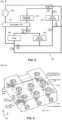
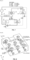
- the thermal management system 102 comprises a heat ventilation and air conditioning system (HVAC) condenser 103, an evaporator-condenser 104, an HVAC evaporator 105, a chiller 106, an accumulator/IHX (Internal Heat Exchanger) 107, and a compressor 108.
- HVAC heat ventilation and air conditioning system
- the valve block 100 comprises eight valves, referred to as 1 to 8.
- the 1 st valve, 1 ensures the management of the refrigerant fluid into the HVAC condenser 103, the 1 st valve being arranged to be connected to the compressor 108.
- the 2 nd valve, 2 ensures the management of the refrigerant fluid into the evaporator-condenser 104, the 2 nd valve being arranged to be connected to the compressor 8.
- the 3 rd valve, 3, is arranged between an exit of the HVAC condenser 103 and the 8 th valve, 8.
- the 4 th valve, 4 is arranged between the exit of the HVAC condenser 103 and the 7 th valve, 7.
- the 5 th valve, 5, ensures the management of the refrigerant fluid into the chiller 106, arranged between the 6 th valve, 6, and able to be connected to the chiller 106.
- the 6 th valve, 6, is arranged between an exit of the accumulator/IHX 107 and the 5 th valve.
- the 7 th valve, 7, is arranged between the 4 th valve and the accumulator/IHX 107, and the 8 th valve, 8, is arranged between the 3 rd valve and the accumulator/IHX 107.
- all the valves 1 to 8 can open and close in two directions. At least valves 4, 5 and 6, and preferably all the valves can expand in both directions.
- valves In a cabin cooling mode illustrated in figures 6 and 7 , the arrangement of the valves is the following:
- the compressor ensures the circulation of the refrigerant fluid (in a high pressure, high temperature, gaseous state) through the 2 nd valve to the evaporator-condenser that works as a condenser.
- the refrigerant fluid cools down and condenses into the liquid phase.
- the fluid then flows to the expansion (6 th ) valve where it is regulated to flow at a proper rate before penetrating the HVAC evaporator where it evaporates and returns to the compressor through the 8th valve and the accumulator.
- the air of the cabin is cooled down thanks to the thermal exchanges with the refrigerant fluid in the HVAC evaporator.
- valves In a battery cooling mode illustrated in figures 8 and 9 , the arrangement of the valves is the following:
- the compressor ensures the circulation of the refrigerant fluid (in a high pressure, high temperature, gaseous state) through the 2 nd valve to the evaporator-condenser that works as a condenser.
- the refrigerant fluid cools down and condenses into the liquid phase.
- the fluid then flows to the expansion (5 th ) valve through the 6 th valve.
- the expansion valve the fluid is regulated to flow at a proper rate before penetrating the chiller where it evaporates and returns to the compressor through the accumulator while the 8 th valve is closed.
- the battery is cooled down by a coolant that is cooled down thanks to the thermal exchanges with the refrigerant fluid in the chiller.
- valves In a heat pump mode illustrated in figures 10 and 11 , the cabin being heated with the ambient heat, the arrangement of the valves is the following:
- the compressor ensures the circulation of the refrigerant fluid (in a high pressure, high temperature, gaseous state) through the 1 st valve to the HVAC condenser.
- the HVAC condenser In the HVAC condenser, the cabin air is heated while the refrigerant fluid cools down. The fluid then flows to the expansion (4 th ) valve wherein the fluid is regulated to flow at a proper rate before penetrating the evaporator-condenser working as an evaporator.
- the refrigerant fluid evaporates and returns to the compressor through the 6 th valve, the HVAC evaporator, the 8 th valve and the accumulator.
- the HVAC evaporator ensures the dehumidification of the air flowing through the HVAC condenser.
- valves 12 and 13 In another heat pump mode, illustrated in figures 12 and 13 , the cabin being heated with the ambient heat and further providing heat recovery, the arrangement of the valves is the following:
- the compressor ensures the circulation of the refrigerant fluid (in a high pressure, high temperature, gaseous state) through the 1 st valve to the HVAC condenser.
- the HVAC condenser In the HVAC condenser, the cabin air is heated while the refrigerant fluid cools down and condenses into the liquid phase. The fluid then flows to the expansion (4 th ) valve wherein the fluid is regulated to flow at a proper rate before penetrating the evaporator-condenser working as an evaporator.
- the refrigerant fluid evaporates and returns to the compressor through two distinct circuit: in a first circuit, the fluid flows through the 6 th valve, the HVAC evaporator, for dehumidification, the 8 th valve and the accumulator, and, in a second circuit, the fluid flows through the 5 th valve and the chiller.
- the refrigerant recovers heat from the coolant which has been heated up by, for example, the electrical motor of the vehicle (further heat recovery inside through the chiller.
- valve block 100 is now detailed.
- the valve block 100 comprises a main body 10.
- the main body 10 present a general parallelepiped form.
- Each valve 1 to 8 comprises a bore 11-1 to 11-8 inside the main body 10 of the valve block 100.
- all the valves of the distributing device 102 are centralized on one single distribution block, the valve block 100.
- Each bore 11-1, ..., 11-8 is a cylinder extending to along an axis called valve axis, referred to as A-1 to A-8.
- the axis A1 to A8 are all parallel. Although not limitating, the axis A1 to A8 extend along the vertical Z-direction in the figures.
- the 1 st valve, the 3 rd valve and the 8 th valve are aligned in the sense that a same straight line, called L1, is perpendicular to the valve axis A1 of the 1 st valve, the valve axis A3 of the 3 rd valve, and the valve axis A8 of the 8 th valve.
- the line L1 extends along the Y-direction in the figures.
- the 7 th valve, the 4 th valve and the 2 nd valve are aligned in the sense that a same straight line, called L2, is perpendicular to the valve axis A7 of the 7 th valve, the valve axis A4 of the 4 th valve, and the valve axis A2 of the 2 nd valve.
- the 5 th valve and the 6 th valve are aligned in the sense that a same straight line, called L3, is perpendicular to the valve axis A5 of the 5 th valve and to the valve axis A6 of the 6 th valve.
- the lines L1 to L3 are preferably parallel one to another.
- the invention is not limited by this configuration and one of the lines can be inclined from the other ones.
- L3 can have an inclined angle compared to L1 and L2.
- the 1 st valve, the 2 nd valve and the 6 th valve are aligned in the sense that a same straight line, called LL1, is perpendicular to the valve axis A1 of the 1 st valve, the valve axis A2 of the 2 nd valve, and the valve axis A6 of the 6 th valve.
- the line LL1 extends along the X-direction in the figures.
- the 3 rd valve and the 4 th valve are aligned in the sense that a same straight line, called LL2, is perpendicular to the valve axis A3 of the 3 rd valve and to the valve axis A4 of the 4 th valve.
- the 8 th valve, the 7 th valve and the 5 th valve are aligned in the sense that a same straight line, called LL3, is perpendicular to the valve axis A8 of the 8 th valve, the valve axis A7 of the 7 th valve, and the valve axis A5 of the 5 th valve.
- the lines LL1 to LL3 are preferably parallel one to another.
- the invention is not limited by this configuration and one of the lines can be inclined from the other ones.
- LL3 can have an inclined angle compared to LL1 and LL2.
- the lines LL1 to LL3 are perpendicular to the lines L1 to L3.
- each valve comprises an entry channel 12-1, ..., 12-8 for feeding the valve with the refrigerant fluid and at least an exit channel, 13-1,..., 13-8, for exiting the refrigerant from the valve.
- Said channels are bores inside the main body 10 of the valve block 100.
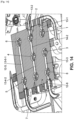
- the channels extend preferably either along the X-direction or the Y-direction, on two levels along the Z-direction, a first level called low level (LL), and a second level, called high level (HL).
- LL low level
- HL high level
- At least a few valves also comprise one or a plurality of bypass channel 14-1, ..., so that the refrigerant fluid can flow in the valve block while bypassing the valve.
- the bypass channels 14-1, ... extend preferably either along the X-direction or the Y-direction, either on the low level LL or the high level HL.
- the entry channel 12-1 extends from the outside of the main body 10 along the X-direction at the low level LL and the exit channel 13-1 extends along the Y-direction to the outside of the main body at the high level HL.
- the bypass channel 14-1 extends in the X-direction at the low level LL from the bore of the valve 1 to the bore of the valve 2.
- the bypass channel 14-1 ensures direct fluid connection between the compressor and the valve 2 (by bypassing valve 1).
- the entry channel 12-2 extends along the X-direction at the low level LL and the exit channel 13-2 extends along the Y-direction at the high level HL to the outside of the main body 10.
- the entry channel 12-2 is collinear with the entry channel 12-1.
- the entry channel 12-2 is also the bypass channel 14-1.
- the valve 2 also comprises a bypass channel 14-2 that extends at the high level HL along the Y-direction from the bore of the valve 4 to the bore of the valve 2.
- the bypass channel 14-2 ensures direct fluid connection between the valve 4 and the evaporator-condenser 104 (by bypassing valve 2).
- the entry channel 12-3 extends from the outside of the main body 10 along the X-direction at the low level LL and the exit channel 13-3 extends along the Y-direction at the high level HL
- the exit channel 13-3 fluidly connects the valve 3 to the valve 8.
- the bypass channel 14-3 extends at the low level LL in the X-direction from the bore of the valve 3 to the bore of the valve 4.
- the bypass channel 14-3 is collinear with the entry channel 12-3.
- the bypass channel 14-3 ensures direct fluid connection between the HVAC condenser and the valve 4 (by bypassing the valve 3).
- the bypass channel 14-3 is also the entry channel 12-4 of the valve 4.
- the entry channel 12-4 extends along the X-direction at the low level LL, and a first exit channel 13-4-1 extends along the Y-direction at the high level HL.
- the exit channel 13-4-1 is collinear with the exit channel 13-2.
- the valve 4 also comprises a second exit channel 13-4-2 colinear with the first exit channel 13-4-1 and extends to the valve 8.
- the entry channel 12-5 extends along the Y-direction at the high level HL from the valve 6 and the exit channel 13-5 extends along the X-direction at the low level LL to the outside of the main body 10 (to the chiller 106).
- the entry channel 12-6 extends from the outside of the main body 10 along the Y-direction at the low level LL (to fluidly connect the valve 6 to the evaporator-condenser and the accumulator/IHX).
- the valve 6 comprises two exit channels.
- a first exit channel 13-6-1 is the entry channel 12-5.
- a second exit channel 13-6-2 extends from the valve 6 to the outside of the main body 10 to fluidly connect the valve 6 to the HVAC evaporator 105.
- the second exit channel comprises a first part that extends from the valve 6 at the high level HL and another part extending along the Z-direction from the high level HL to the low level LL and a final portion along the X-direction to the outside of the main body 10.
- the entry channel 12-7 is the exit channel 13-4-2.
- the entry channel 12-8 extends from the outside of the main body 10 along the X-direction at the low level LL to fluidly connect the valve 8 to the HVAC evaporator.
- the exit channel 13-7 of the valve 7 and the exit channel 13-8 of the valve 8 correspond. It extends at the low level LL between the bore of the valve 7 and the bore of the valve 8.
- Another channel 15 extending along the Y-direction fluidly connects the channel 13-7, 13-8 to the outside of the main body 10 (to the accumulator/IHX and the compressor).
- the main body 10 also comprises a channel to connect the main body 10 to the chiller.
- the diameters of the entry, exit and bypass channels are chosen in dependence of the system function. For instance, when the refrigerant fluid is R744: 6 to 8 mm (for the high pressure channels) and 12mm (for the low pressure channels). When the refrigerant fluid is R1234yf: 10-12mm (for the high pressure channels) and 16mm (for the low pressure channels).
- the entry, exit and bypass channels build interfaces to other components of the thermal management system 102 (i.e., for instance, compressor, heat exchangers, refrigerant bottle), which implies that the system 102 comprises very few pipes.
- the refrigerant fluid distribution device is very compact, such that the volume occupied by the thermal management system 102 in the vehicle is reduced. It is also easy to adapt to different system layouts. Connectivities between the valves are minimized, as well as the AC-Pipe routing between the valves. Also, it ensures an easy integration of additional components like check valves or charge valves.
- the process of manufacturing is also simplified since a single block needs to be machined to form the main body 10.
- the main body can be precast instead of machined. At least some of the entry, exit, bypass channels could be diagonal channels instead of perpendicular channels.
- the valve module could also integrate additional components, like check valves, PT (pressure temperature)-sensors, charge valves. It is possible to operate a direct connectivity of the valve island with other components, for example a chiller. Other types of valves could be used (i.e. shut off valve, closed-expansion (CE) valve, closed expansion full open (CEO) valves). The integration of the valves could be from different sides, i.e. opposite top and bottom sides.
- the valve module can be adapted to different refrigerants, i.e. R744, R1234yf, R134a, R290 and others.
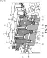
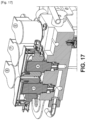
- a valve is now detailed with reference to figures 1 , 3 , 4 , 16 and 17 .
- each valve 1, ...8, comprises a plunger or piston 20 that extends longitudinally along the axis of the valve between an upper end 21 and a bottom end 22.
- the upper end 21 is fixed to a housing 23 of the valve.
- the piston 20 is of a general cylinder form and is able to slide into the bore valve 11-1,..., 11-8 against an internal wall of the bore valve between a closed position and an open position.
- the bottom end 22 rests against a seat of the valve, which prevents fluid from flowing through the valve.
- the bottom end 22 is spaced from the seat of the valve, which authorizes the fluid flowing through the valve.
- the upper part of the valves comprises a shoulder 24 corresponding of a diameter reduction of the piston 24.
- the diameter reduction ensures the flowing of the fluid in the entry, exit and bypass channels that are located at the high level HL.
Landscapes
- Engineering & Computer Science (AREA)
- Mechanical Engineering (AREA)
- Chemical & Material Sciences (AREA)
- Combustion & Propulsion (AREA)
- Transportation (AREA)
- General Engineering & Computer Science (AREA)
- Physics & Mathematics (AREA)
- Thermal Sciences (AREA)
- Air-Conditioning For Vehicles (AREA)
Priority Applications (2)
| Application Number | Priority Date | Filing Date | Title |
|---|---|---|---|
| EP23194990.0A EP4517145A1 (de) | 2023-09-01 | 2023-09-01 | Ventilmodul für eine kältemittelverteilungsvorrichtung eines wärmeregelungssystems |
| PCT/EP2024/073782 WO2025045802A1 (en) | 2023-09-01 | 2024-08-26 | Valve module for a refrigerant distribution device of a thermal management system |
Applications Claiming Priority (1)
| Application Number | Priority Date | Filing Date | Title |
|---|---|---|---|
| EP23194990.0A EP4517145A1 (de) | 2023-09-01 | 2023-09-01 | Ventilmodul für eine kältemittelverteilungsvorrichtung eines wärmeregelungssystems |
Publications (1)
| Publication Number | Publication Date |
|---|---|
| EP4517145A1 true EP4517145A1 (de) | 2025-03-05 |
Family
ID=87930327
Family Applications (1)
| Application Number | Title | Priority Date | Filing Date |
|---|---|---|---|
| EP23194990.0A Withdrawn EP4517145A1 (de) | 2023-09-01 | 2023-09-01 | Ventilmodul für eine kältemittelverteilungsvorrichtung eines wärmeregelungssystems |
Country Status (2)
| Country | Link |
|---|---|
| EP (1) | EP4517145A1 (de) |
| WO (1) | WO2025045802A1 (de) |
Citations (5)
| Publication number | Priority date | Publication date | Assignee | Title |
|---|---|---|---|---|
| EP1441160A2 (de) * | 2003-01-27 | 2004-07-28 | Bürkert Werke GmbH & Co. KG | Ventilgruppe |
| WO2014060762A2 (en) * | 2012-10-17 | 2014-04-24 | Norgren Limited | Fluid control module for waste heat recovery systems |
| EP3499101A1 (de) * | 2017-12-12 | 2019-06-19 | Danfoss A/S | Ventilanordnung für einen operationsmoduswähler |
| WO2022105352A1 (zh) * | 2020-11-23 | 2022-05-27 | 艾泰斯热系统研发(上海)有限公司 | 多负载热泵系统的冷却液冷热源切换装置 |
| CN115195379A (zh) * | 2021-04-12 | 2022-10-18 | 浙江三花汽车零部件有限公司 | 流体控制装置及车辆热管理系统 |
-
2023
- 2023-09-01 EP EP23194990.0A patent/EP4517145A1/de not_active Withdrawn
-
2024
- 2024-08-26 WO PCT/EP2024/073782 patent/WO2025045802A1/en active Pending
Patent Citations (5)
| Publication number | Priority date | Publication date | Assignee | Title |
|---|---|---|---|---|
| EP1441160A2 (de) * | 2003-01-27 | 2004-07-28 | Bürkert Werke GmbH & Co. KG | Ventilgruppe |
| WO2014060762A2 (en) * | 2012-10-17 | 2014-04-24 | Norgren Limited | Fluid control module for waste heat recovery systems |
| EP3499101A1 (de) * | 2017-12-12 | 2019-06-19 | Danfoss A/S | Ventilanordnung für einen operationsmoduswähler |
| WO2022105352A1 (zh) * | 2020-11-23 | 2022-05-27 | 艾泰斯热系统研发(上海)有限公司 | 多负载热泵系统的冷却液冷热源切换装置 |
| CN115195379A (zh) * | 2021-04-12 | 2022-10-18 | 浙江三花汽车零部件有限公司 | 流体控制装置及车辆热管理系统 |
Also Published As
| Publication number | Publication date |
|---|---|
| WO2025045802A1 (en) | 2025-03-06 |
Similar Documents
| Publication | Publication Date | Title |
|---|---|---|
| US11724561B2 (en) | Device for regulating a flow through and distributing a fluid in a fluid circuit | |
| EP3419843B1 (de) | Fahrzeugwärmeverwaltungssystem und wärmetauscher | |
| US9016080B2 (en) | Battery heating and cooling system | |
| US9494350B2 (en) | Plate-type heat pump air conditioner heat exchanger for a unitary heat pump air conditioner | |
| US9239193B2 (en) | Unitary heat pump air conditioner having a heat exchanger with an integral receiver and sub-cooler | |
| EP2629040B1 (de) | Wärmepumpenklimaanlage mit Wärmetauscher mit integriertem Sammler und Unterkühler | |
| CN113811725B (zh) | 热泵系统 | |
| EP2336681A1 (de) | Ölausgleichsvorrichtung, kompressoreinheit und ölausgleichsverfahren | |
| JP2026053755A (ja) | マニホールド | |
| US20160265819A1 (en) | Air-conditioning system of a motor vehicle and method for operating the air-conditioning system | |
| US12441158B2 (en) | Valve set integrated module, vehicle thermal management system, and vehicle | |
| WO2022253122A1 (zh) | 阀组集成模块、热管理系统及车辆 | |
| US11981185B2 (en) | Refrigerant module of integrated thermal management system for vehicle | |
| WO2025045802A1 (en) | Valve module for a refrigerant distribution device of a thermal management system | |
| CN119546469A (zh) | 歧管流体模块 | |
| EP1867937A1 (de) | Dampfkompressions-Kältekreislauf und Fahrzeugklimaanlagensystem damit | |
| CN113623192B (zh) | 基于电子水泵控制空调制冷剂流量分配方法和新能源汽车 | |
| CN119428095B (zh) | 一种汽车热管理系统及其控制方法 | |
| KR20230111483A (ko) | 차량용 보조 냉방모듈 및 이를 구비한 차량 냉방 시스템 | |
| EP4696531A1 (de) | Verteiler | |
| CN119239249B (zh) | 一种车辆热管理系统和车辆 | |
| CN121515666A (zh) | 集成模块和具有其的热管理系统、车辆 | |
| CN121515665A (zh) | 集成模块和具有其的热管理系统、车辆 | |
| EP4317894A1 (de) | Kältemittelmodul für ein thermisches managementsystem | |
| CN109689406A (zh) | 用于机动车的冷却装置以及具有这种冷却装置的机动车 |
Legal Events
| Date | Code | Title | Description |
|---|---|---|---|
| PUAI | Public reference made under article 153(3) epc to a published international application that has entered the european phase |
Free format text: ORIGINAL CODE: 0009012 |
|
| STAA | Information on the status of an ep patent application or granted ep patent |
Free format text: STATUS: THE APPLICATION HAS BEEN PUBLISHED |
|
| AK | Designated contracting states |
Kind code of ref document: A1 Designated state(s): AL AT BE BG CH CY CZ DE DK EE ES FI FR GB GR HR HU IE IS IT LI LT LU LV MC ME MK MT NL NO PL PT RO RS SE SI SK SM TR |
|
| STAA | Information on the status of an ep patent application or granted ep patent |
Free format text: STATUS: THE APPLICATION IS DEEMED TO BE WITHDRAWN |
|
| 18D | Application deemed to be withdrawn |
Effective date: 20250906 |