EP4517190A1 - Filteranordnung für eine extraktionsvorrichtung und extraktionsvorrichtung oder kombinationsgerät - Google Patents
Filteranordnung für eine extraktionsvorrichtung und extraktionsvorrichtung oder kombinationsgerät Download PDFInfo
- Publication number
- EP4517190A1 EP4517190A1 EP23193728.5A EP23193728A EP4517190A1 EP 4517190 A1 EP4517190 A1 EP 4517190A1 EP 23193728 A EP23193728 A EP 23193728A EP 4517190 A1 EP4517190 A1 EP 4517190A1
- Authority
- EP
- European Patent Office
- Prior art keywords
- filter
- filter assembly
- extraction device
- air entry
- entry opening
- Prior art date
- Legal status (The legal status is an assumption and is not a legal conclusion. Google has not performed a legal analysis and makes no representation as to the accuracy of the status listed.)
- Pending
Links
Images


Classifications
-
- F—MECHANICAL ENGINEERING; LIGHTING; HEATING; WEAPONS; BLASTING
- F24—HEATING; RANGES; VENTILATING
- F24C—DOMESTIC STOVES OR RANGES ; DETAILS OF DOMESTIC STOVES OR RANGES, OF GENERAL APPLICATION
- F24C15/00—Details
- F24C15/20—Removing cooking fumes
- F24C15/2035—Arrangement or mounting of filters
-
- F—MECHANICAL ENGINEERING; LIGHTING; HEATING; WEAPONS; BLASTING
- F24—HEATING; RANGES; VENTILATING
- F24C—DOMESTIC STOVES OR RANGES ; DETAILS OF DOMESTIC STOVES OR RANGES, OF GENERAL APPLICATION
- F24C15/00—Details
- F24C15/20—Removing cooking fumes
- F24C15/2042—Devices for removing cooking fumes structurally associated with a cooking range e.g. downdraft
Definitions
- the present invention relates to a filter assembly for an extraction device according to claim 1.
- the present invention relates further to an extraction device or a combination appliance comprising a cooking hob and an extraction device according to claim 13.
- cooking hobs comprise cooking zones for placement of cookware receiving the food to be cooked.
- the cooking zones are generally arranged on a cooktop, in particular a glass ceramic cooktop, which forms an upper wall of the cooking hob.
- cooking fumes are generated, which are distributed over the cooking area.
- an extraction hood above the cooking area for an aspiration of these fumes.
- such kind of a combination appliance comprises a cooking hob and an integrated downdraft extraction device with an extraction opening in the cooktop of the cooking hob.
- a cooking hob and an extraction device With this combination of a cooking hob and an extraction device, a compact solution is provided.
- Extraction hood or extraction device can be operated in parallel to the cooking hob, thereby sucking in those cooking fumes in order to filter out particles and tiny droplets for a recirculated operating process and/or to blow the cooking fumes to the outside of the building.
- the extraction hood or the combination appliance with a downdraft extraction device usually operates with recirculating air, which is blown out into a kitchen cabinet or directly into the ambient air after it has been filtered.
- an odour filter element in addition to a grease filter element in an air duct of the extraction hood or the extraction device.
- Filter elements need a regular maintenance in order to comply with the required filtering functionality.
- a grease filter element could become clogged by grease particles, if it is not regularly cleaned by removing those particles.
- Such grease filter cleansing is particularly executable by removing the grease filter or a filter carrier including the grease filter from the extraction device and by washing the respective element or unit in a dishwasher.
- a filter element and filter carrier in the manner described is in particular disclosed in the international patent application WO 2022/028724 A1 .
- an extraction device or a combination appliance comprising a cooking hob and an extraction device shall be provided, which is operable with such a filter assembly, so that it also contributes to a simplified handling process, specifically for the maintenance of the filter assembly.
- a filter assembly for an extraction device is provided.
- the extraction device is in particular an extraction hood or an extraction device of a combination appliance, which further comprises a cooking hob.
- the filter assembly comprises at least one filter element and a filter carrier.
- the at least one filter element may be a grease filter element and/or an odour filter element and/or any other particle filter or a combination of such filter types.
- the at least one filter element is preferably a separate component, which is connected, in particular detachably connected, to a supporting structure or frame structure of the filter carrier.
- the filter assembly, particularly the filter carrier comprises a two-dimensional air entry opening, which is preferably arrangeable in the extraction device or in the combination appliance comprising such an extraction device in a horizontal direction.
- the filter assembly comprises two first opposite lateral surfaces, which are arranged perpendicularly to or in an inclined orientation towards the two-dimensional air entry opening.
- the two first opposite lateral surfaces are particularly arranged in an at least approximate U-shape or V-shape.
- the filter assembly in particular the filter carrier, further comprises two second opposite lateral surfaces arranged perpendicularly to or in an inclined orientation towards the two-dimensional air entry opening.
- the two-dimensional air entry opening and the two first and second opposite lateral surfaces in particular form an at least approximately cuboid or pyramid-shaped or truncated pyramid-shaped box structure.
- the at least one filter element forms an at least essential portion of one of the two first opposite lateral surfaces.
- a filter assembly which allows or supports a simplified handling of the filter assembly, particularly for a maintenance process provided thereon. More specifically, the filter assembly designed according to the present invention may advantageously be removed from the extraction device, by taking it from the extraction device as a whole.
- the at least one filter element is detachably and/or mechanically connected to the supporting structure or frame structure of the filter carrier.
- the connection is based on at least one of a snapping or latching mechanism, a clinching or screw connection, and a magnetic force coupling.
- the connection may be designed in that connection means are provided at outer edges of the filter element. In case of a filter element with a polygonal construction, said outer connection means are arranged preferably next to corners of such a filter element.
- a first filter element and a second filter element are arranged in the filter assembly, in particular at the filter carrier, more specifically at the supporting structure or frame structure of the filter carrier.
- the arrangement may be designed in such way that each one of the first and second filter elements form an at least essential portion of the related one of the two first opposite lateral surfaces. That way, the air that is intended to be filtered by the filter assembly, after having passed the two-dimensional air entry opening, may be split up into two portions, with a first portion flowing through the first filter element and a second portion flowing through the second filter element.
- the entire filter surface of the filter assembly is increased, more specifically doubled, by such an implementation of two filter elements, instead of only one, in the filter assembly.
- the at least one filter element has a flat shape, which may be a rectangular shape.
- Naturally other filter element geometries like circular or oval may be selectable.
- One particularly preferred embodiment of a filter assembly is characterized in that the lateral edge of the two-dimensional air entry opening, which lateral edge is allocated to that one the two first opposite lateral surfaces which comprises the at least one filter element, is longer than the maximum width of the filter element.
- both lateral edges allocated to the two filter elements are longer than the maximum width of the related filter element.
- At least one of the two second opposite lateral surfaces is an entirely closed surface. More specifically, an air-tight and/or liquid-tight surface may be provided. Such an entirely closed surface is suitable for a guidance of spilled liquids, which enters the filter assembly, to a collection area. Moreover, the closed surface is particularly advantageous for an improved airflow guidance.
- At least one of the two second opposite lateral surfaces is or comprises a curved surface.
- This particular shape may also contribute to a favourably improved guidance of spilled liquids and airflow after their entrance into the filter assembly.
- the curved surface is preferably an entirely closed surface, more preferably an air-tight and/or liquid-tight surface, further contributing to an improved liquid and airflow guidance.
- sealing means water spilled on the cooktop surface is prevented from entering the interior of the extraction device, in particular through an area or gap between the filter seat and the filter carrier. More specifically, by providing the sealing means, the spilled water is guided to the filter assembly, in particular to the previously mentioned collection area of the filter assembly.
- the first sealing means comprises at least a first part or component of a labyrinth sealing.
- the second sealing means comprises at least a second part or component of a labyrinth sealing.
- the first and second sealing means in particular the cooperating first and second sealing means, more specifically the labyrinth sealing, provide for a circumferential sealing, what provides for entire sealing of the interior of the extraction device.
- the sealing effect preferably makes use of gravity acting on the filter assembly, particularly supporting the sealing effect of a labyrinth sealing.
- a removal handle may be arranged at the filter assembly.
- the removal handle is preferably positioned at least close to the two-dimensional air entry opening, more preferably at a frame part surrounding the two-dimensional air entry opening.
- the removal handle may be used at least for an initial lifting of the filter assembly in order to provide for a better grabbing of the entire filter assembly and a possible removal of the filter assembly with the operator's two hands.
- the removal handle is or comprises a tongue or projection, which is preferably arranged at a frame part surrounding the two-dimensional air entry opening and/or protruding into the two-dimensional air entry opening.
- an extraction device or a combination appliance comprises a cooking hob, which comprises a cover plate or cooktop, in particular a glass plate.
- the cover plate or cooktop has an opening or a recess formed therein.
- the combination appliance further comprises an extraction device, which is arranged below the cooking hob, in particular below the cover plate or cooktop of the cooking hob.
- the extraction device or the combination appliance comprises or is configured to include the filter assembly according to anyone of the herein disclosed embodiments, in particular as previously described.
- the extraction device or combination appliance is designed in a way that it contributes to a simplified handling process, specifically as performed during the maintenance of the filter assembly.
- the extraction device or combination appliance further comprises a filter seat, which receives and/or supports the filter assembly.
- the filter seat is arranged downstream of and/or is accessible through the opening or recess.
- the filter assembly is preferably insertable in and removable from the filter seat as a whole.
- the filter assembly is removable from the combination appliance through the opening or recess, in particular removable either after removal of a lid or grid, which covers or is configured to cover the opening or recess of the cover plate or cooktop, or in combination with the lid or grid.
- the filter seat comprises a support structure supporting or configured to support at least the frame part surrounding the two-dimensional air entry opening of the filter assembly.
- the support structure particularly comprises the second sealing means or component of the labyrinth sealing. That means, the at least a first sealing means or component, on the one hand, and the second sealing means or component, on the other hand, form the labyrinth sealing after their merging. Accordingly, the labyrinth sealing may by formed by a coupling of a specific upper section, e.g. an upper edging, of the filter seat and a specific lower section, e.g. a lower edging, of the frame part surrounding the two-dimensional air entry opening of the filter assembly.
- the filter seat comprises a curved support element or surface, with a curvature that is compatible with the curvature of the curved surface of the at least one of the two second opposite lateral surfaces of the filter assembly.
- the term compatible with the curvature may mean that similar radii of curvature are provided for these surfaces.
- the said curved surfaces are aligned or alignable one above the other.
- further support may be provided by at least a portion of the curved surface, preferably by the entire curved surface.
- Fig. 1 illustrates a general setup of a combination appliance 10 comprising a cooking hob 12 and a downdraft extraction device 14 installed in a kitchen cabinet 16.
- the combination appliance 10 illustrated in Figs. 1 and 2 presents a structure of a combination appliance 10 according to a first example.
- the combination appliance 10 is implemented in a cut-out of a kitchen countertop 18 forming a top cover plate of the kitchen cabinet 16.
- the downdraft extraction device 14 is configured to take away cooking vapours occurring during cooking processes, in particular when cooking with uncovered cookware.
- a housing 28 of the extraction device 14 is shown in Fig. 1 in transparent illustration.
- Said housing 28 provides a closed outer shell or channel segment for a flow of the sucked-in cooking vapours on their way from the suction opening 24 to an exhaust opening 30 in a base area 32 of the kitchen cabinet 16.
- Said exhaust opening 30 is also covered, namely by an outlet grille 34.
- the flow of the sucked-in cooking vapours through the extraction device 14 is driven by the operation of an extraction fan 36 arranged inside of the housing 28.
- Said extraction fan 36 comprises a bottom-sided intake opening 38 for sucking the cooking vapours from the interior space of the housing 28.
- a rear-sided fan outlet is arranged for a horizontal exit of the air blown out backwards from the extraction fan housing 42.
- the fan outlet is connected to a first end of an air duct 44 designed as a rectangular tube and forms a second channel arranged downstream the above-mentioned first channel.
- an air duct bending by 90 degrees is implemented, which redirects the air flow from horizontal to vertical downwards.
- the air duct 44 may be guided alongside a rear side of the kitchen cabinet 16 and may be bent again by 90 degrees close to a rear lower edge of the kitchen cabinet 16 in order to direct the airflow towards exhaust opening 30 in the base area 32 of the kitchen cabinet 16. Accordingly, the second end of the air duct 44 is connected to the exhaust opening 30.
- the embodiment illustrated in Fig. 1 shows a solution of the air duct 44 with an inclined section of its downwardly directed portion, directed slightly to the right. Naturally, a solution with said portion arranged in an exact vertical direction is considerable as well.
- the cross-sectional view of Fig. 2 further shows two power boards 54, one for the left cooking region 20a and one for the right cooking region 20b, the power boards 54 providing cooking zones in the left and right cooking regions 20a, 20b with electrical power.
- the cooking hob 12 is an induction cooking hob and the cooking zones are defined by induction coils (not shown) that are arranged below the cooktop 22 of the cooking hob 12. Attached to the bottom side of the power board 54 assigned to the right cooking region 20b, a further circuit board is arranged forming a control electronics 56 for the combination appliance 10.
- the embodiment illustrated in Figs. 3 to 7 is a structure of a combination appliance 10 according to a second example.
- the combination appliance 10 according to second example provides a modular setup for a combination appliance 10 with a general downdraft extraction device 14, which can be combined with different models of cooking hobs 12.
- the combination appliance embodiment according to Figs. 3 to 7 further differs from the setup of the combination appliance 10 according to Figs. 1 and 2 in that all parts or modules of the cooking hob 12, except the two power board modules 54, are aggregated in a hob assembly part 12', which is dimensioned such that this hob assembly 12' will entirely find place in a cut-out area provided by a kitchen installer in a standard kitchen countertop 18, whereas said non-accommodated power board modules 54 are attached to an outer surface of the housing 28 of the extraction device 14, as will be described more in detail further down below.
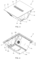
- Figs. 3 to 5 show the combination appliance 10 according to the second example from different views.
- Fig. 6 which is an illustration from a similar view as that one of Fig. 3 , but which is a presentation of the isolated extraction device 14, i. e. without the hob assembly 12' on the top side of the extraction device 14, core part of the extraction device 14 is the housing 28 having a standardized dimensioning.
- This housing part 28 is configured to receive nearly all the extraction device components except, on the one hand, the components accommodated in the cooking hob 12, which are the suction opening 24 including its cover grid 26 and an initial section of the suction duct, and, on the other hand, a fan control module 58, which is also attached to an outer surface of the housing 28 of the extraction device 14.
- the housing 28 of the general extraction device 14 is formed as a plastic box or plastic container of prism-shaped nature.
- Two opposing side walls of the housing 28, which are first 28a and second 28b side walls, are inclined from the vertical axis.
- the other two opposing and essentially trapezoid third 28c and fourth 28d side walls are vertically oriented in installation alignment.
- the four side walls 28a, 28b, 28c, 28d form a box, more precisely a container, which is tapered towards its bottom wall 28e.
- Said box or container is open at the top, but sealed by a bottom wall 60 of the housing 62 of the cooking hob 12 after completed assembling of the combination appliance 10.
- the perspective bottom view according to Fig. 4 shows a bottom side of a fluid collector 64 arranged in a section of the bottom wall 28e, which may be formed like a shell open to the top, i. e. to the interior of the extraction device housing 28.
- the fluid collector 64 may be configured to be pulled down from the bottom wall 28e of the housing 28 for emptying it. Preferably, said pulling down is only possible after a lateral movement of the fluid collector 64 and/or by unlocking a locking mechanism.
- Other embodiments, not shown in the figures may include another opening in the bottom wall 28e of the extraction device housing 28 arranged in another section of the bottom wall 28e, which another opening may serve as a service opening for providing service activities. Said another opening allows access to the interior of the extraction device housing 28 and is closable by a closing lid, preferably by a sealed closing lid, in this respect preventing passage of fluid not collected in the fluid collector 64 and/or passage of conveyed air.
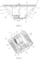
- Fig. 6 grants an inside from the top into the arrangement of components inside of the extraction device housing 28.
- An air transportation system including a fan 36 for air conveyance is positioned along a central axis of the extraction device housing 28.
- the fan 36 is arranged in a vertical orientation, i. e. a rotation axis of a fan wheel (not shown) is horizontally aligned.
- the fan 36 comprises two intake openings 38, 38' arranged at opposing sides of a fan housing 42, which construction enables a symmetric intake of air from both halves of the interior of the extraction device housing 28.
- Fig. 6 grants an inside from the top into the arrangement of components inside of the extraction device housing 28.
- An air transportation system including a fan 36 for air conveyance is positioned along a central axis of the extraction device housing 28.
- the fan 36 is arranged in a vertical orientation, i. e. a rotation axis of a fan wheel (not shown) is horizontally aligned.
- the fan 36 comprises
- a filter assembly 48 which in this specific embodiment is represented by two filter carriers 50, arranged in parallel to each other and axially symmetrical similarly to the fan 36, with a flat grease filter element (not particularly shown in Fig. 7 ) implemented in each one of the two filter carriers 50, is included for a filtration the conveyed air and for a separation of grease particles and/or droplets.
- Said filter assembly 48 and filter carrier 50, on the one hand, and fan 36, on the other hand, are arranged next to each other.
- the cooking vapours aspirated through the suction opening 24 enter the filter assembly 48 from the top side, and are deflected by about 90 degrees from vertical to horizontal direction fairly equally to both sides and through the filter elements.
- the filter assembly 48 After passing the filter elements another deflection by about 90 degrees, but in approximately horizontal direction, takes place, so that the conveyed air is forwarded to the two intake openings 38, 38' for its transportation via the fan housing 42 to exhaust opening 30 positioned at the fourth side wall 28d, which is a rear wall in installation orientation of the combination appliance 10.
- the filter assembly 48 only takes up space of a smaller extension in depth direction of the cooking hob 12, the suction opening 24 extends nearly over the entire cooking hob depth, which means that a portion of the suction opening 24 is arranged above the fan housing 42, however, the cooking vapours aspirated through that portion are immediately guided towards the filter assembly 48, i. e. initially nearly in parallel to the surface of the cooktop 22.
- the filter assembly 48 may be positioned above the previously described fluid collector 64, so that condensed droplets may directly drop down into the fluid collector 64.
- both the power board modules 54 and the fan control module 58 are attached to the outer surfaces of housing walls, quasi in a backpack manner.
- the two power board modules i. e. first and second power board modules 54
- the fan control module 58 is attached to the third side wall 28c, which is a front wall of the extraction device housing 28 in installation orientation.
- the fan control module 58 is positioned at an opposing side in relation to the exhaust outlet 30, which is arranged in the fourth side wall 28d, which is the rear wall in the present embodiment.
- the filter assembly 48 according to Figs. 7 to 16 differs from the filter assembly as illustrated in Fig. 6 .
- a filter seat 68 for the accommodation of the filter assembly 48 is provided in the combination appliance 10.
- Fig. 7 illustrates the implementation of the filter assembly 48 in the combination appliance 10 by only presenting the filter seat 68, i.e. the filter assembly 48 with included filter elements 66 with their mesh filter structures are removed from the filter seat 68.
- the filter seat 68 specifically includes an accommodation casing 72 with a passage opening for the passage of filtered air on its way to the intake openings 38, 38' of the extraction fan 36.
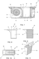
- FIGs. 8 to 11 more details about the design of the filter assembly 48 and the related filter seat 68 are illustrated.
- the filter seat 68 is shown in Fig. 8 in an isolated illustration by way of a cross-sectional view thereof. Accordingly, the illustrated passage opening 70 is, in the direction of vision, on the reverse side of the accommodation casing 72 of the filter seat 68.
- the filter seat 68 is, in airflow direction, arranged immediately downstream of the suction opening 24, with the consequence, that an inlet opening 74 of the filter seat 68 may comply with, or may be directly coupled with, the suction opening 24 of the combination appliance 10.
- the design of the filter seat 68 provides for a specific extent of the inlet opening 74 of the filter seat 68 in comparison with the width of the rectangularly designed passage opening 70. More specifically, the inlet opening 74 of the filter seat 68 has a larger longitudinal extent than the width, i.e. the upper and lower sides of the passage opening 70 as illustrated in Fig. 8 ., of the rectangularly designed passage opening 70.
- the two-dimensional suction opening 24 and the related inlet opening 74 of the filter seat 68 is designed with a transverse section, which is large enough for an aspiration of all cooking fumes generated by cooking processes on an extensive cooking surface on cooktop 22.
- a transition surface 76 is included in the filter seat 68.
- Said transition surface could for example be a linear ramp, however, due to the fact that the transition surface 76 is directly positioned on the fan housing 42, which is rounded in this area, the transition surface 76 has a curved structure, specifically similar to a curved rectangle.
- an air entry opening 78 of the filter carrier 50 and its successive air ducting parts which are incorporated or incorporable in the inlet opening 74 of the filter seat 68 and its successive parts in a downstream direction, are adjusted, i.e. equalized, in their designs, with the consequence of the curved transition surface 76 of the filter seat 68 being reproduced in the filter carrier 50, namely as an air guiding surface 80, which is arranged in the filter carrier 50 immediately downstream of its air entry opening 78.
- the term “reproduce” may mean in this context, that the curvatures of the transition surface 76 and the air guidance surface 80 are compatible with each other, more specifically, similar radii of curvatures are provided for these surfaces.
- said curved surfaces 76, 80 are arranged one above the other.
- the filter elements 66 of the filter assembly 48 are aligned with the position of the passage openings 70 of the filter seat 68.
- the air guiding surface 80 of the filter carrier 50 works as a guiding means for aspirated cooking fumes during their way from the air entry opening 78 of the filter carrier 50 to the filter elements 66.
- This airflow is indicated by arrow A in Fig. 11 , which figure shows, together with Fig. 10 , further views of the filter assembly 48, that way disclosing further details of this assembly.
- Fig. 11 particularly discloses a lifting tongue 88, arranged at that wall of the filter carrier 50, which is opposite to the wall comprising the transition surface 76.
- the lifting tongue 88 is located on the centreline of the filter carrier 50.
- the lifting tongue 88 can be used by the operator of the combination appliance 10 during maintenance activities, namely for the performance of a lifting movement of the filter assembly 48, at least for an initial lifting of the filter assembly 48, specifically when it is still completely included in the filter seat 68, in order to provide for a better grabbing of the entire filter assembly 48 and a possible removal of the filter assembly 48 with the operator's two hands.
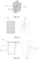
- the filter carrier 50 and the filter elements 66 are designed in a way, which allows a filter element detachment only with a special tool.
- the filter elements 66 are attached to the filter carrier 50 using hardly dismountable coupling means.
- These coupling means are better illustrated by the presentations according to Figs. 13 and 14 illustrating one of the filter elements 66 ( Fig. 13 ) and a related installation area at the filter carrier 50 ( Fig. 14 ), as well as related enlarged views of these coupling means, which are represented by, on the one hand, a small recess 82 at a frame of the filter element 66, and, on the other hand, a spring hook 84 at a frame structure 86 of the filter carrier 50.
- Fig. 15 and 16 illustrate two cross-sections of a circumferential labyrinth sealing 90, 92 arranged in the area of two opposite edges of a frame part of the air entry opening 78, which arrangement is schematically indicated by details "XV" and "XVI” in Fig. 7 .
- the labyrinth sealing 90, 92 is provided for preventing such a bypassing.
- the labyrinth sealing 90, 92 includes a first part arranged at a bottom side of the frame part of the air entry opening 78, which is a circumferential elevation part 90, and a second part arranged at an upper side of the filter casing 50 in the area of the inlet opening 74 of the filter seat 68, which is a likewise circumferential groove part 92. Elevation part 90 and groove part 92 match in their designs in that, when paired, only a very small gap 94 is left, which gap 94 in an imagined passage direction for bypassing air is extended compared to two adjacent parallel surfaces, i. e. without a provision of a labyrinth sealing 90, 92.
- the respective passage resistance is increased, which causes the sealing effect of the labyrinth sealing 90, 92.
- the sealing effect is particularly further enhanced in that, due to gravity force, the filter assembly 48 is pressed against filter seat 68, with the effect of a particular small gap size.
- the labyrinth sealing is also suited for a prevention of an entry of spilled liquids into the inlet opening 74 of the filter seat 68, instead of a desired forwarding of these spilled liquids into the filter carrier 50, which also comprises means for a proper treatment of such spillages.
- the suction opening 24 of the extraction device 14 is covered by a cover grid 26.
- the cover grid 26 rests on a related support area arranged at the suction opening 24 and is kept in position by gravity. Hence, an operator of the combination appliance 10 can easily remove the cover grid 26 from the air channel 66, in particular for cleaning activities, and insert it again in reverse order.
Landscapes
- Engineering & Computer Science (AREA)
- Chemical & Material Sciences (AREA)
- Combustion & Propulsion (AREA)
- Mechanical Engineering (AREA)
- General Engineering & Computer Science (AREA)
- Filtering Of Dispersed Particles In Gases (AREA)
Priority Applications (3)
| Application Number | Priority Date | Filing Date | Title |
|---|---|---|---|
| EP23193728.5A EP4517190A1 (de) | 2023-08-28 | 2023-08-28 | Filteranordnung für eine extraktionsvorrichtung und extraktionsvorrichtung oder kombinationsgerät |
| PCT/EP2024/072182 WO2025045525A1 (en) | 2023-08-28 | 2024-08-05 | Filter assembly for an extraction device and extraction device or combination appliance |
| AU2024333507A AU2024333507A1 (en) | 2023-08-28 | 2024-08-05 | Filter assembly for an extraction device and extraction device or combination appliance |
Applications Claiming Priority (1)
| Application Number | Priority Date | Filing Date | Title |
|---|---|---|---|
| EP23193728.5A EP4517190A1 (de) | 2023-08-28 | 2023-08-28 | Filteranordnung für eine extraktionsvorrichtung und extraktionsvorrichtung oder kombinationsgerät |
Publications (1)
| Publication Number | Publication Date |
|---|---|
| EP4517190A1 true EP4517190A1 (de) | 2025-03-05 |
Family
ID=87848119
Family Applications (1)
| Application Number | Title | Priority Date | Filing Date |
|---|---|---|---|
| EP23193728.5A Pending EP4517190A1 (de) | 2023-08-28 | 2023-08-28 | Filteranordnung für eine extraktionsvorrichtung und extraktionsvorrichtung oder kombinationsgerät |
Country Status (3)
| Country | Link |
|---|---|
| EP (1) | EP4517190A1 (de) |
| AU (1) | AU2024333507A1 (de) |
| WO (1) | WO2025045525A1 (de) |
Citations (5)
| Publication number | Priority date | Publication date | Assignee | Title |
|---|---|---|---|---|
| WO2019197055A1 (de) * | 2018-04-10 | 2019-10-17 | BSH Hausgeräte GmbH | Filtervorrichtung und dunstabzugsvorrichtung mit filtervorrichtung |
| DE102018213743A1 (de) * | 2018-08-15 | 2020-02-20 | Wilhelm Bruckbauer | Filtereinsatz für eine Dunstabzugsvorrichtung zum Abzug von Kochdünsten nach unten |
| US20210063234A1 (en) * | 2018-01-12 | 2021-03-04 | Elica S.P.A. | Cooktops with integrated extraction hoods and scales |
| EP3789680A1 (de) * | 2019-09-04 | 2021-03-10 | BSH Hausgeräte GmbH | Filtereinheit und dunstabzugsvorrichtung mit filtereinheit |
| WO2022028724A1 (en) | 2020-08-05 | 2022-02-10 | Electrolux Appliances Aktiebolag | Combination appliance |
Family Cites Families (2)
| Publication number | Priority date | Publication date | Assignee | Title |
|---|---|---|---|---|
| CN116336519B (zh) * | 2021-12-24 | 2026-03-20 | 佛山市顺德区美的电热电器制造有限公司 | 分离器、吸油烟机和烟灶一体机 |
| CN217472962U (zh) * | 2022-05-13 | 2022-09-23 | 佛山市顺德区美的电热电器制造有限公司 | 分离组件和集成灶 |
-
2023
- 2023-08-28 EP EP23193728.5A patent/EP4517190A1/de active Pending
-
2024
- 2024-08-05 WO PCT/EP2024/072182 patent/WO2025045525A1/en active Pending
- 2024-08-05 AU AU2024333507A patent/AU2024333507A1/en active Pending
Patent Citations (5)
| Publication number | Priority date | Publication date | Assignee | Title |
|---|---|---|---|---|
| US20210063234A1 (en) * | 2018-01-12 | 2021-03-04 | Elica S.P.A. | Cooktops with integrated extraction hoods and scales |
| WO2019197055A1 (de) * | 2018-04-10 | 2019-10-17 | BSH Hausgeräte GmbH | Filtervorrichtung und dunstabzugsvorrichtung mit filtervorrichtung |
| DE102018213743A1 (de) * | 2018-08-15 | 2020-02-20 | Wilhelm Bruckbauer | Filtereinsatz für eine Dunstabzugsvorrichtung zum Abzug von Kochdünsten nach unten |
| EP3789680A1 (de) * | 2019-09-04 | 2021-03-10 | BSH Hausgeräte GmbH | Filtereinheit und dunstabzugsvorrichtung mit filtereinheit |
| WO2022028724A1 (en) | 2020-08-05 | 2022-02-10 | Electrolux Appliances Aktiebolag | Combination appliance |
Also Published As
| Publication number | Publication date |
|---|---|
| WO2025045525A1 (en) | 2025-03-06 |
| AU2024333507A1 (en) | 2026-02-19 |
Similar Documents
| Publication | Publication Date | Title |
|---|---|---|
| US12259141B2 (en) | Combination appliance | |
| US11168893B2 (en) | Cooktops | |
| CA3028836C (en) | Insert for a downdraft extractor | |
| CN1332153C (zh) | 炉灶上方的多功能微波炉 | |
| CN113646588A (zh) | 具有抽油烟机设备和灶台的组合设备 | |
| CN110578943A (zh) | 烟雾排出装置和带有烟雾排出装置和灶台的组合设备 | |
| KR102262806B1 (ko) | 공기 흡인을 동반한 추출기 장치 | |
| EP4517190A1 (de) | Filteranordnung für eine extraktionsvorrichtung und extraktionsvorrichtung oder kombinationsgerät | |
| KR20240116240A (ko) | 조리 기기 | |
| EP4332441A1 (de) | Filteranordnung und kombinationsgerät | |
| CN208784374U (zh) | 烹饪器具 | |
| EP4471335A1 (de) | Abdeckelement für eine einlassöffnung einer extraktionsvorrichtung | |
| CN219693371U (zh) | 一种吸油烟机风道结构、吸油烟机 | |
| US20240247811A1 (en) | Cooking apparatus | |
| AU2023331637A1 (en) | Filter element or assembly, fume extraction unit and combination appliance | |
| KR20260042049A (ko) | 조리기기 | |
| KR20260039409A (ko) | 조리기기 |
Legal Events
| Date | Code | Title | Description |
|---|---|---|---|
| PUAI | Public reference made under article 153(3) epc to a published international application that has entered the european phase |
Free format text: ORIGINAL CODE: 0009012 |
|
| STAA | Information on the status of an ep patent application or granted ep patent |
Free format text: STATUS: THE APPLICATION HAS BEEN PUBLISHED |
|
| AK | Designated contracting states |
Kind code of ref document: A1 Designated state(s): AL AT BE BG CH CY CZ DE DK EE ES FI FR GB GR HR HU IE IS IT LI LT LU LV MC ME MK MT NL NO PL PT RO RS SE SI SK SM TR |
|
| STAA | Information on the status of an ep patent application or granted ep patent |
Free format text: STATUS: REQUEST FOR EXAMINATION WAS MADE |
|
| 17P | Request for examination filed |
Effective date: 20250905 |