EP4517193A1 - Système de chauffage - Google Patents
Système de chauffage Download PDFInfo
- Publication number
- EP4517193A1 EP4517193A1 EP23193915.8A EP23193915A EP4517193A1 EP 4517193 A1 EP4517193 A1 EP 4517193A1 EP 23193915 A EP23193915 A EP 23193915A EP 4517193 A1 EP4517193 A1 EP 4517193A1
- Authority
- EP
- European Patent Office
- Prior art keywords
- fluid
- heat
- buffer tank
- buffer
- fluid circuit
- Prior art date
- Legal status (The legal status is an assumption and is not a legal conclusion. Google has not performed a legal analysis and makes no representation as to the accuracy of the status listed.)
- Withdrawn
Links
Images



Classifications
-
- F—MECHANICAL ENGINEERING; LIGHTING; HEATING; WEAPONS; BLASTING
- F24—HEATING; RANGES; VENTILATING
- F24H—FLUID HEATERS, e.g. WATER OR AIR HEATERS, HAVING HEAT-GENERATING MEANS, e.g. HEAT PUMPS, IN GENERAL
- F24H4/00—Fluid heaters characterised by the use of heat pumps
- F24H4/02—Water heaters
- F24H4/04—Storage heaters
-
- F—MECHANICAL ENGINEERING; LIGHTING; HEATING; WEAPONS; BLASTING
- F24—HEATING; RANGES; VENTILATING
- F24D—DOMESTIC- OR SPACE-HEATING SYSTEMS, e.g. CENTRAL HEATING SYSTEMS; DOMESTIC HOT-WATER SUPPLY SYSTEMS; ELEMENTS OR COMPONENTS THEREFOR
- F24D11/00—Central heating systems using heat accumulated in storage masses
- F24D11/02—Central heating systems using heat accumulated in storage masses using heat pumps
- F24D11/0214—Central heating systems using heat accumulated in storage masses using heat pumps water heating system
-
- F—MECHANICAL ENGINEERING; LIGHTING; HEATING; WEAPONS; BLASTING
- F24—HEATING; RANGES; VENTILATING
- F24D—DOMESTIC- OR SPACE-HEATING SYSTEMS, e.g. CENTRAL HEATING SYSTEMS; DOMESTIC HOT-WATER SUPPLY SYSTEMS; ELEMENTS OR COMPONENTS THEREFOR
- F24D3/00—Hot-water central heating systems
- F24D3/08—Hot-water central heating systems in combination with systems for domestic hot-water supply
- F24D3/082—Hot water storage tanks specially adapted therefor
-
- F—MECHANICAL ENGINEERING; LIGHTING; HEATING; WEAPONS; BLASTING
- F24—HEATING; RANGES; VENTILATING
- F24H—FLUID HEATERS, e.g. WATER OR AIR HEATERS, HAVING HEAT-GENERATING MEANS, e.g. HEAT PUMPS, IN GENERAL
- F24H1/00—Water heaters, e.g. boilers, continuous-flow heaters or water-storage heaters
- F24H1/18—Water-storage heaters
- F24H1/20—Water-storage heaters with immersed heating elements, e.g. electric elements or furnace tubes
- F24H1/201—Water-storage heaters with immersed heating elements, e.g. electric elements or furnace tubes using electric energy supply
- F24H1/202—Water-storage heaters with immersed heating elements, e.g. electric elements or furnace tubes using electric energy supply with resistances
-
- F—MECHANICAL ENGINEERING; LIGHTING; HEATING; WEAPONS; BLASTING
- F24—HEATING; RANGES; VENTILATING
- F24H—FLUID HEATERS, e.g. WATER OR AIR HEATERS, HAVING HEAT-GENERATING MEANS, e.g. HEAT PUMPS, IN GENERAL
- F24H1/00—Water heaters, e.g. boilers, continuous-flow heaters or water-storage heaters
- F24H1/18—Water-storage heaters
- F24H1/20—Water-storage heaters with immersed heating elements, e.g. electric elements or furnace tubes
- F24H1/208—Water-storage heaters with immersed heating elements, e.g. electric elements or furnace tubes with tubes filled with heat transfer fluid
-
- F—MECHANICAL ENGINEERING; LIGHTING; HEATING; WEAPONS; BLASTING
- F24—HEATING; RANGES; VENTILATING
- F24H—FLUID HEATERS, e.g. WATER OR AIR HEATERS, HAVING HEAT-GENERATING MEANS, e.g. HEAT PUMPS, IN GENERAL
- F24H9/00—Details
- F24H9/02—Casings; Cover lids; Ornamental panels
-
- F—MECHANICAL ENGINEERING; LIGHTING; HEATING; WEAPONS; BLASTING
- F28—HEAT EXCHANGE IN GENERAL
- F28D—HEAT-EXCHANGE APPARATUS, NOT PROVIDED FOR IN ANOTHER SUBCLASS, IN WHICH THE HEAT-EXCHANGE MEDIA DO NOT COME INTO DIRECT CONTACT
- F28D1/00—Heat-exchange apparatus having stationary conduit assemblies for one heat-exchange medium only, the media being in contact with different sides of the conduit wall, in which the other heat-exchange medium is a large body of fluid, e.g. domestic or motor car radiators
- F28D1/02—Heat-exchange apparatus having stationary conduit assemblies for one heat-exchange medium only, the media being in contact with different sides of the conduit wall, in which the other heat-exchange medium is a large body of fluid, e.g. domestic or motor car radiators with heat-exchange conduits immersed in the body of fluid
- F28D1/0233—Heat-exchange apparatus having stationary conduit assemblies for one heat-exchange medium only, the media being in contact with different sides of the conduit wall, in which the other heat-exchange medium is a large body of fluid, e.g. domestic or motor car radiators with heat-exchange conduits immersed in the body of fluid with air flow channels
- F28D1/024—Heat-exchange apparatus having stationary conduit assemblies for one heat-exchange medium only, the media being in contact with different sides of the conduit wall, in which the other heat-exchange medium is a large body of fluid, e.g. domestic or motor car radiators with heat-exchange conduits immersed in the body of fluid with air flow channels with an air driving element
-
- F—MECHANICAL ENGINEERING; LIGHTING; HEATING; WEAPONS; BLASTING
- F28—HEAT EXCHANGE IN GENERAL
- F28D—HEAT-EXCHANGE APPARATUS, NOT PROVIDED FOR IN ANOTHER SUBCLASS, IN WHICH THE HEAT-EXCHANGE MEDIA DO NOT COME INTO DIRECT CONTACT
- F28D1/00—Heat-exchange apparatus having stationary conduit assemblies for one heat-exchange medium only, the media being in contact with different sides of the conduit wall, in which the other heat-exchange medium is a large body of fluid, e.g. domestic or motor car radiators
- F28D1/02—Heat-exchange apparatus having stationary conduit assemblies for one heat-exchange medium only, the media being in contact with different sides of the conduit wall, in which the other heat-exchange medium is a large body of fluid, e.g. domestic or motor car radiators with heat-exchange conduits immersed in the body of fluid
- F28D1/04—Heat-exchange apparatus having stationary conduit assemblies for one heat-exchange medium only, the media being in contact with different sides of the conduit wall, in which the other heat-exchange medium is a large body of fluid, e.g. domestic or motor car radiators with heat-exchange conduits immersed in the body of fluid with tubular conduits
- F28D1/0408—Multi-circuit heat exchangers, e.g. integrating different heat exchange sections in the same unit or heat exchangers for more than two fluids
- F28D1/0426—Multi-circuit heat exchangers, e.g. integrating different heat exchange sections in the same unit or heat exchangers for more than two fluids with units having particular arrangement relative to the large body of fluid, e.g. with interleaved units or with adjacent heat exchange units in common air flow or with units extending at an angle to each other or with units arranged around a central element
- F28D1/0443—Combination of units extending one beside or one above the other
-
- F—MECHANICAL ENGINEERING; LIGHTING; HEATING; WEAPONS; BLASTING
- F24—HEATING; RANGES; VENTILATING
- F24D—DOMESTIC- OR SPACE-HEATING SYSTEMS, e.g. CENTRAL HEATING SYSTEMS; DOMESTIC HOT-WATER SUPPLY SYSTEMS; ELEMENTS OR COMPONENTS THEREFOR
- F24D2200/00—Heat sources or energy sources
- F24D2200/08—Electric heater
-
- F—MECHANICAL ENGINEERING; LIGHTING; HEATING; WEAPONS; BLASTING
- F24—HEATING; RANGES; VENTILATING
- F24D—DOMESTIC- OR SPACE-HEATING SYSTEMS, e.g. CENTRAL HEATING SYSTEMS; DOMESTIC HOT-WATER SUPPLY SYSTEMS; ELEMENTS OR COMPONENTS THEREFOR
- F24D2200/00—Heat sources or energy sources
- F24D2200/12—Heat pump
-
- F—MECHANICAL ENGINEERING; LIGHTING; HEATING; WEAPONS; BLASTING
- F24—HEATING; RANGES; VENTILATING
- F24D—DOMESTIC- OR SPACE-HEATING SYSTEMS, e.g. CENTRAL HEATING SYSTEMS; DOMESTIC HOT-WATER SUPPLY SYSTEMS; ELEMENTS OR COMPONENTS THEREFOR
- F24D2220/00—Components of central heating installations excluding heat sources
- F24D2220/10—Heat storage materials, e.g. phase change materials or static water enclosed in a space
-
- F—MECHANICAL ENGINEERING; LIGHTING; HEATING; WEAPONS; BLASTING
- F28—HEAT EXCHANGE IN GENERAL
- F28D—HEAT-EXCHANGE APPARATUS, NOT PROVIDED FOR IN ANOTHER SUBCLASS, IN WHICH THE HEAT-EXCHANGE MEDIA DO NOT COME INTO DIRECT CONTACT
- F28D21/00—Heat-exchange apparatus not covered by any of the groups F28D1/00 - F28D20/00
- F28D2021/0019—Other heat exchangers for particular applications; Heat exchange systems not otherwise provided for
- F28D2021/0028—Other heat exchangers for particular applications; Heat exchange systems not otherwise provided for for cooling heat generating elements, e.g. for cooling electronic components or electric devices
- F28D2021/0031—Radiators for recooling a coolant of cooling systems
Definitions
- the present invention relates to a heating system, in particular a sustainable heating system.
- heat pumps extract heat from its surroundings and provides that heat to another circuit which in turn heat the house or for domestic hot water. Heat pumps are able to do this to an extent, as a consequence of which the amount of heating is limited and for optimal efficiency these heat pumps need to be combined with low temperature heating systems, which are typically not provided for in older houses.
- low temperature heating systems which are typically not provided for in older houses.
- heat pumps When replacing oil or gas boilers with heat pumps, the complete heating system of a household would need to be replaced, reducing the desirability of these heat pumps.
- alternative heating solutions typically require a large amount of additional feature and, more importantly, a large amount of additional space to function.
- the invention thereto provides a heating system according to claim 1.
- the system uses a heat pump to heat a body of water. This heated body of water is subsequently used to provide heating in a house or hot water for example.
- the heat pump for example extracts heat from the air, such as ambient air, or it pulls air from a warm place in a home, such as an attic. This heat is used to warm a fluid in the fluid circuit of the heat pump. This heat can for example be absorbed by the fluid circuit of the heat pump.
- the fluid of the heat pump is a refrigerant, more preferably a natural refrigerant.
- the fluid of the heat pump is propane or carbon dioxide based.
- the heated fluid in the fluid circuit of the heat pump can for example give off its heat by means of a (coiled) heat exchanger or condenser.
- the buffer tank also houses a further fluid circuit, which is in heat exchanging contact with the heat pump circuit.
- the further fluid circuit is a (coiled) heat exchanger.
- the heat exchanging contact is an indirect contact, where the heat exchanger heats up the buffer fluid and the buffer fluid heats up the further fluid circuit.
- the further fluid in the further fluid circuit can be water.
- the invention may thus provide a heating system for heating a home, comprising a heat pump provided with a first fluid circuit, configured to heat a first fluid in the first fluid circuit; a buffer tank, comprising at least one inlet for receiving a second fluid and at least one outlet for delivering the second fluid; and comprising a buffer fluid; a second fluid circuit extending between the inlet and the outlet of the buffer tank; wherein the first fluid circuit extends at least partially into the buffer tank, to heat the buffer fluid; and wherein the first and second fluid circuits are at least partially in heat exchanging contact within the buffer tank.
- the heat pump preferably comprises an air extractor, to extract heat from ambient air and/or an air exhaust, to exhaust air from the heat pump to the surroundings.
- the heat pump may thus use the surrounding heat, for example in a house or ventilation air, to extract heat from and transfer the heat to the fluid in its fluid circuit.
- the used air may then be expelled from the system via the exhaust.
- the temperature of the used air may be lower than the temperature of the extracted ambient air and/or air exhaust, in particular the temperature of the expelled used air may be lower than the temperature of the extracted ambient air and/or air exhaust.
- the buffer tank may comprise an opening allowing at least a part of the first fluid circuit to access the interior of the buffer tank.
- the opening may be an inlet and/or an outlet allowing at least a part of the first fluid circuit to return and leave the interior of the buffer tank.
- the heat pump may be arranged close to the buffer tank, the connection between the two still needs to be made.
- the buffer tank and the heat pump are integrated, forming a single unit.
- the heating system may further comprise a third fluid circuit extending between a third inlet and a third outlet of the buffer tank comprising the buffer fluid, wherein the third fluid circuit optionally comprises a heating element, such as a radiator, in heat exchanging contact with the buffer fluid in the third fluid circuit.
- the heating system may be used to heat not only the buffer tank or domestic hot water (DHW), but also for example rooms in the house.
- DHW domestic hot water
- the buffer tank may comprise a phase changing material, which is used to store heat upon a phase change.
- a phase changing material which is used to store heat upon a phase change.
- the use of such material allows heat to be efficiently stored in a relatively small volume, decreasing the size of the buffer device needed to store or provide a set amount of energy.
- the phase changing material also provides heat upon changing is phase, in particular to heat fluid in the system, more in particular to heat the buffer fluid in the system.
- the phase changing material has a phase changing temperature between 30 and 90 degrees Celsius, in particular between 40 and 80, more in particular between 60 and 75 degrees Celsius, more in particular between 48 and 58 degrees Celsius.
- Phase Changing Materials are known in the art and use heat needed or provided by changing phase, such that the materials may be considered as some form of thermal battery or storage for the present heating system. Since the melting temperature of these materials is higher it is possible to obtain a high specific energy density.
- the phase changing materials in the buffer device basically the effective volume used for heat storage can be improved or, the other way around, the volume needed to store a specific amount of energy can be reduced. Less volume means a smaller buffer device can be used, which allows to use heating systems according to the invention in a broader range of applications.
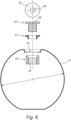
- the phase changing material may comprise spheres or shells, preferably made of a metal and more preferably of stainless steel, wherein the spheres or shells preferably comprise or are at least partially filled with a salt hydrate.
- the phase changing material comprises balls, preferably made of a metal and more preferably of stainless steel, wherein the balls preferably comprise or are at least partially filled with a salt hydrate.
- Salt hydrates comprise an alloy of inorganic salts and water, which materials are relatively cheap and easily accessible.
- the change of phase of these salt hydrates comprises hydration and dehydration of the salts, very similar to the process of melting and freezing, wherein salt hydrates have a relatively high latent warmth per mass and thus able to store and give off relative large amounts of warmth.
- a large surface is available to exchange heat between the phase changing material and the fluid in the buffer device.
- metal or stainless steel a good heat exchange can be obtained.
- a diameter is chosen of 63 mm ⁇ for the stainless steel spheres or balls in buffer tanks with a maximum volume of 500L.
- the phase changing material is separated from the rest, in particular the fluid, of the buffer tank to prevent any unwanted interactions or reactions between the phase changing material and the rest.
- the phase changing material may have a heat or warmth storage capacity of 80 to 140 kWh/m3, in particular about 100-120 kWh/m3. In comparison, water has a capacity of about 20-30 kWh/m3. Compared to a volume of water, using these phase change materials is thus much more efficient.
- the buffer tank may be provided with a heating element, such as an electric heating element, to heat up the buffer fluid in the buffer tank.
- a heating element such as an electric heating element
- the buffer tank may have an upper side and a bottom side, wherein the inlet is provided in the bottom side and the outlet is provided in the upper side.
- a natural heat gradient over the tank will be cold fluid at the bottom and warm fluid at the top.
- the first and second fluid circuit each may comprise a coiled section, wherein in particular at least a part of the coiled section of the first fluid circuit is provided within the coiled section of the second fluid circuit.
- Coiled sections in particular coiled copper tubing, has been used for a long time for it's efficient heat transfer capabilities. By placing the two circuits in close proximity, for instance by having one within the centre space of the other, allows for an improved heat exchange between the two systems or circuits, further improving the efficiency of the system.
- the coiled sections may be coiled stainless steel or copper tubing.
- the system may optionally comprise a solar panel for providing electricity to the heat pump.
- the system comprises a plurality of (photo voltaic) solar panels.
- the fluid circuits may, for example the second fluid circuit or each fluid circuit, comprise a thermal solar collector, for warming fluid in the circuit. In all circuits solar energy may thus be used to provide additional electrical input and heat to the system, without relying on further fossil fuels.
- the buffer tank may comprise at least one, preferably at least two sensors, to monitor temperatures insides the buffer tank, which sensors may be arranged at different heights of the buffer tank.
- the buffer tank may be placed in an upright position, with its longitudinal axis along a vertical. This allows the buffer tank to be placed in small areas such as under roofing or other suitable places in the house. It is also possible to place the buffer tank in a flat position, with its longitudinal position along a horizontal, which allows the buffer tank to be placed in other areas such as under roofing and other more difficult accessible parts of a house.
- the heat pump may be provided on top of the buffer tank, preferably directly on top. This way a very compact heating system may be designed. Moreover, it allows the integration of the two components in a single unit. This has the large benefit that the system can be wired up and connected beforehand, in a controlled environment and installing the system is almost plug and play.
- the heat pump is housed in a first housing and the buffer tank is housed in a second housing, wherein the two housings are attached to each other, wherein preferably the first housing is arranged directly on top of the second housing.
- the buffer device or buffer tank may have a total capacity of 200-500L which, when comprising phase changing materials, is sufficient to replace existing conventional systems.
- the buffer device is well insulated, to maintain as much heat as possible.
- the system may also comprise circulating pumps, for pumping around fluid in the circuits of the system.
- each circuit may comprise its own pump, or even multiple pumps per circuit.
- the fluid circuits may each comprise a flow controller, to control the flow of fluid though the circuits. Depending on the temperature of the fluid to be heated by the heat pump, the flow of that fluid may be regulated.
- the flow controller may be an adjustable flow controller.
- the second fluid circuit may comprise a flow switch, for example arranged at the inlet of the circuit. The flow switch may be used to detect the flow of the second fluid, for instance when (warm) tap water is requested by the system.
- the third fluid circuit may comprise a valve, in particular a three-way-valve, in between the third exit and the heating element and/or in between the third exit and the third inlet.
- the valve is arranged such that a normally closed position connects the valve and the heating element or radiator and a normally open position connects the valve and the third inlet.
- the second fluid circuit may comprise a pump, for instance arranged between the valve and/or heating element on one side, and the third inlet on the other side, for creating a flow in the second fluid circuit.
- the heating system may be provided with a controller, to operate components of the system.
- the controller is preferably in contact with at least the heat pump and the buffer device, more preferably with at least the heat pump and temperature sensors of the buffer device.
- the controller is connected to the pumps, valves, flow switch(es) and flow controllers.
- the controller may be configured to control the components of the system depending on measured input.
- the heat pump of the system or the buffer tank may be arranged to operate within a certain temperature bandwidth. It is furthermore imaginable that controller is configured to control the components of the system depending on predetermined input.
- the heating system, in particular the heat pump can be arranged to operate within a predetermined period and/or time frame of the day.
- the system may also comprise a thermostat, which may be arranged to measure the temperature in a room, which thermostat is in contact with the controller. When the thermostat determines that the temperature is below a set temperature, the controller may control the valve to send fluid through the heating element of the second fluid circuit, to increase the temperature that way.
- a thermostat which may be arranged to measure the temperature in a room, which thermostat is in contact with the controller. When the thermostat determines that the temperature is below a set temperature, the controller may control the valve to send fluid through the heating element of the second fluid circuit, to increase the temperature that way.
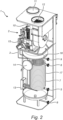
- FIGs 1 and 2 schematically shows a heating system (1) for heating a home, according to the present invention, comprising a heat pump (2).
- the heat pump (2) is provided with a first fluid circuit (3) and the heat pump (2) is configured to heat a first fluid in the first fluid circuit (3).
- the first fluid can be a refrigerant.
- Shown in figure 1 is also the buffer tank (4), which has been hidden in figure 2 , comprising at least one inlet (5) for receiving a second fluid and at least one outlet (6) for delivering the second fluid; and comprising a buffer fluid.
- a second fluid circuit (7) extends between the inlet (5) and the outlet (6) of the buffer tank (4) as can be seen in figure 2 .
- the first fluid circuit (3) extends at least partially into the buffer tank (4), to heat the buffer fluid and the first (3) and second (7) fluid circuits are at least partially in heat exchanging contact within the buffer tank (4), in the shown embodiment of figure 2 they are in best heat exchanging contact between the outlet (6) and inlet (5).
- the heat pump (2) is arranged right on top of the tank (4).
- the first (3) and second (7) fluid circuit each comprise a coiled section (16, 17), wherein in particular at least a part of the coiled section (16) of the first fluid circuit (3) is provided within the coiled section (17) of the second fluid circuit (7).
- the inlet (5) for example is used to feed, relatively cold, tap water to the circuit (7). Upon travelling towards the outlet (6) this water heats up and exits the circuit (7) as hot water via the outlet (6).
- the system (1) comprises a third fluid circuit extending between a third inlet (8) and a third outlet (9) of the buffer tank(4), wherein the third fluid circuit may be used with a radiator, in heat exchanging contact with the buffer fluid in the third fluid circuit.
- the inlets (5, 8) on the tank (4) are located on the bottom portion of the tank, whereas the outlets (6, 9) are located on upper portions of the tank.
- the heat pump (2) shown comprises an air extractor (10), to extract heat from ambient air and/or an air intake (11) and/or an air exhaust (12), to intake and exhaust air from the heat pump to the surroundings.
- the buffer tank (4) is also provided with a heating element (13) to heat up the buffer fluid in the buffer tank (4) and a flange (14) allowing access to the inside of the tank (4).
- the system (1) is further provided with a controller (15), controlling operation of the system (1).
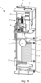
- the inside of the buffer tank (4) may comprise a number of balls filled with phase changing material to increase the buffer capacity of the tank (4).
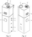
- FIGs 3 and 4 show perspective views on the heating system (1) as shown in figures 1 and 2 , in covers.
- the complete system (1) this way forms an integrated single piece, which needs installing by attaching the inlets (5, 8), outlets (6, 9) and air intake and outtake (11, 12).
- FIG 8 schematically shows a system according to the invention, integrated to a home heating system.
- a cold water source (18) is shown, delivering cold water to the inlet (5).
- hot water exits via the outlet (6) to a hot water point, such as a shower (19).
- a heating device in the form of a radiator (20).
- Hot fluid leaves the tank (4) via the outlet (9), via a valve (21) to the radiator (20) to give off heat. Fluid that has passed through the radiator (20) is fed back to the inlet (8), in this case via a pump (22).
- the valve (21) can be used to bypass this heating device loop and send fluid from the outlet (9) to the inlet (8) directly. This would increase heating in the section of the coiled sections (16, 17).
- the buffer tank (4) further comprises balls (31) filled with phase changing material arranged to be in heat exchanging contact with the buffer fluid.
Landscapes
- Engineering & Computer Science (AREA)
- Physics & Mathematics (AREA)
- Thermal Sciences (AREA)
- Mechanical Engineering (AREA)
- General Engineering & Computer Science (AREA)
- Chemical & Material Sciences (AREA)
- Combustion & Propulsion (AREA)
- Water Supply & Treatment (AREA)
- Steam Or Hot-Water Central Heating Systems (AREA)
Priority Applications (1)
| Application Number | Priority Date | Filing Date | Title |
|---|---|---|---|
| EP23193915.8A EP4517193A1 (fr) | 2023-08-29 | 2023-08-29 | Système de chauffage |
Applications Claiming Priority (1)
| Application Number | Priority Date | Filing Date | Title |
|---|---|---|---|
| EP23193915.8A EP4517193A1 (fr) | 2023-08-29 | 2023-08-29 | Système de chauffage |
Publications (1)
| Publication Number | Publication Date |
|---|---|
| EP4517193A1 true EP4517193A1 (fr) | 2025-03-05 |
Family
ID=87863353
Family Applications (1)
| Application Number | Title | Priority Date | Filing Date |
|---|---|---|---|
| EP23193915.8A Withdrawn EP4517193A1 (fr) | 2023-08-29 | 2023-08-29 | Système de chauffage |
Country Status (1)
| Country | Link |
|---|---|
| EP (1) | EP4517193A1 (fr) |
Citations (4)
| Publication number | Priority date | Publication date | Assignee | Title |
|---|---|---|---|---|
| WO2007090861A1 (fr) * | 2006-02-09 | 2007-08-16 | Electricite De France | Dispositif echangeur de chaleur destine aux systemes de chauffage ou de climatisation |
| EP1965164B1 (fr) * | 2007-02-28 | 2010-04-21 | Atlantic Climatisation et Ventilation | Dispositif d'échange de chaleur entre des fluides appartenant à deux circuits |
| WO2015004101A1 (fr) * | 2013-07-11 | 2015-01-15 | Tecumseh Europe S.A | Assemblage d'une machine thermodynamique |
| WO2022168029A1 (fr) * | 2021-02-07 | 2022-08-11 | Octopus Energy Group Limited | Procédés de conception et de commande d'installations d'alimentation en eau chaude |
-
2023
- 2023-08-29 EP EP23193915.8A patent/EP4517193A1/fr not_active Withdrawn
Patent Citations (4)
| Publication number | Priority date | Publication date | Assignee | Title |
|---|---|---|---|---|
| WO2007090861A1 (fr) * | 2006-02-09 | 2007-08-16 | Electricite De France | Dispositif echangeur de chaleur destine aux systemes de chauffage ou de climatisation |
| EP1965164B1 (fr) * | 2007-02-28 | 2010-04-21 | Atlantic Climatisation et Ventilation | Dispositif d'échange de chaleur entre des fluides appartenant à deux circuits |
| WO2015004101A1 (fr) * | 2013-07-11 | 2015-01-15 | Tecumseh Europe S.A | Assemblage d'une machine thermodynamique |
| WO2022168029A1 (fr) * | 2021-02-07 | 2022-08-11 | Octopus Energy Group Limited | Procédés de conception et de commande d'installations d'alimentation en eau chaude |
Similar Documents
| Publication | Publication Date | Title |
|---|---|---|
| CN102695924B (zh) | 能量存储系统 | |
| JP5012695B2 (ja) | 給湯システム | |
| KR101760791B1 (ko) | 에너지 저장 시스템 | |
| US7451611B2 (en) | Solar air conditioning system | |
| US7543456B2 (en) | Heat pump liquid heater | |
| US7007858B2 (en) | Compact boiler with tankless heater for providing heat and domestic hot water and method of operation | |
| US20090032760A1 (en) | Rotational multi vane positive displacement valve for use with a solar air conditioning system | |
| CN109716052A (zh) | 利用制冷剂和相变材料加热水的设备和方法 | |
| HU231149B1 (hu) | Szilárd töltetű hőtároló berendezés | |
| JP5464195B2 (ja) | 太陽熱利用ヒートポンプ給湯システム | |
| JP2008064372A (ja) | 熱交換器型蓄熱システム | |
| US9391492B2 (en) | Facility for transforming heat energy | |
| KR100758820B1 (ko) | 지열과 태양열 및 보조열원을 사용하는 급탕 및냉난방시스템과 그 운전제어방법 | |
| JP4485406B2 (ja) | 貯湯式給湯装置 | |
| KR101548073B1 (ko) | 축열조와 분리된 열원의 뜨거운 열을 바로 사용하는 축열식 난방기 및 온수기 | |
| JP5751599B2 (ja) | 給湯冷暖房システム | |
| EP1895241A2 (fr) | Procédé et système pour accumuler l'énergie calorifique | |
| KR20180133689A (ko) | 온수 공급 장치 | |
| US20110278307A1 (en) | Water tank for use with a solar air conditioning system | |
| EP4279822A1 (fr) | Système de chauffage | |
| WO2008114051A2 (fr) | Accumulateur thermique modifié | |
| CN102679610B (zh) | 扩散吸收式制冷机以及用于运行扩散吸收式制冷机的方法 | |
| JP2010014391A (ja) | 給湯システム | |
| CN216977198U (zh) | 空气能热水器的水箱和空气能热水器 | |
| JP6089669B2 (ja) | 給湯システム |
Legal Events
| Date | Code | Title | Description |
|---|---|---|---|
| PUAI | Public reference made under article 153(3) epc to a published international application that has entered the european phase |
Free format text: ORIGINAL CODE: 0009012 |
|
| STAA | Information on the status of an ep patent application or granted ep patent |
Free format text: STATUS: THE APPLICATION HAS BEEN PUBLISHED |
|
| AK | Designated contracting states |
Kind code of ref document: A1 Designated state(s): AL AT BE BG CH CY CZ DE DK EE ES FI FR GB GR HR HU IE IS IT LI LT LU LV MC ME MK MT NL NO PL PT RO RS SE SI SK SM TR |
|
| STAA | Information on the status of an ep patent application or granted ep patent |
Free format text: STATUS: REQUEST FOR EXAMINATION WAS MADE |
|
| 17P | Request for examination filed |
Effective date: 20250905 |
|
| STAA | Information on the status of an ep patent application or granted ep patent |
Free format text: STATUS: THE APPLICATION HAS BEEN WITHDRAWN |
|
| 18W | Application withdrawn |
Effective date: 20251124 |