EP4517228A1 - Integriertes kühlgerät - Google Patents
Integriertes kühlgerät Download PDFInfo
- Publication number
- EP4517228A1 EP4517228A1 EP23795591.9A EP23795591A EP4517228A1 EP 4517228 A1 EP4517228 A1 EP 4517228A1 EP 23795591 A EP23795591 A EP 23795591A EP 4517228 A1 EP4517228 A1 EP 4517228A1
- Authority
- EP
- European Patent Office
- Prior art keywords
- drawer
- storage compartment
- cabinet
- handle
- refrigerator according
- Prior art date
- Legal status (The legal status is an assumption and is not a legal conclusion. Google has not performed a legal analysis and makes no representation as to the accuracy of the status listed.)
- Pending
Links
Images

Classifications
-
- F—MECHANICAL ENGINEERING; LIGHTING; HEATING; WEAPONS; BLASTING
- F25—REFRIGERATION OR COOLING; COMBINED HEATING AND REFRIGERATION SYSTEMS; HEAT PUMP SYSTEMS; MANUFACTURE OR STORAGE OF ICE; LIQUEFACTION SOLIDIFICATION OF GASES
- F25D—REFRIGERATORS; COLD ROOMS; ICE-BOXES; COOLING OR FREEZING APPARATUS NOT OTHERWISE PROVIDED FOR
- F25D25/00—Charging, supporting, and discharging the articles to be cooled
- F25D25/02—Charging, supporting, and discharging the articles to be cooled by shelves
- F25D25/024—Slidable shelves
- F25D25/025—Drawers
-
- F—MECHANICAL ENGINEERING; LIGHTING; HEATING; WEAPONS; BLASTING
- F25—REFRIGERATION OR COOLING; COMBINED HEATING AND REFRIGERATION SYSTEMS; HEAT PUMP SYSTEMS; MANUFACTURE OR STORAGE OF ICE; LIQUEFACTION SOLIDIFICATION OF GASES
- F25D—REFRIGERATORS; COLD ROOMS; ICE-BOXES; COOLING OR FREEZING APPARATUS NOT OTHERWISE PROVIDED FOR
- F25D23/00—General constructional features
- F25D23/06—Walls
- F25D23/069—Cooling space dividing partitions
-
- F—MECHANICAL ENGINEERING; LIGHTING; HEATING; WEAPONS; BLASTING
- F25—REFRIGERATION OR COOLING; COMBINED HEATING AND REFRIGERATION SYSTEMS; HEAT PUMP SYSTEMS; MANUFACTURE OR STORAGE OF ICE; LIQUEFACTION SOLIDIFICATION OF GASES
- F25D—REFRIGERATORS; COLD ROOMS; ICE-BOXES; COOLING OR FREEZING APPARATUS NOT OTHERWISE PROVIDED FOR
- F25D25/00—Charging, supporting, and discharging the articles to be cooled
- F25D25/02—Charging, supporting, and discharging the articles to be cooled by shelves
- F25D25/024—Slidable shelves
-
- F—MECHANICAL ENGINEERING; LIGHTING; HEATING; WEAPONS; BLASTING
- F25—REFRIGERATION OR COOLING; COMBINED HEATING AND REFRIGERATION SYSTEMS; HEAT PUMP SYSTEMS; MANUFACTURE OR STORAGE OF ICE; LIQUEFACTION SOLIDIFICATION OF GASES
- F25D—REFRIGERATORS; COLD ROOMS; ICE-BOXES; COOLING OR FREEZING APPARATUS NOT OTHERWISE PROVIDED FOR
- F25D23/00—General constructional features
- F25D23/06—Walls
- F25D23/065—Details
- F25D23/067—Supporting elements
-
- F—MECHANICAL ENGINEERING; LIGHTING; HEATING; WEAPONS; BLASTING
- F25—REFRIGERATION OR COOLING; COMBINED HEATING AND REFRIGERATION SYSTEMS; HEAT PUMP SYSTEMS; MANUFACTURE OR STORAGE OF ICE; LIQUEFACTION SOLIDIFICATION OF GASES
- F25D—REFRIGERATORS; COLD ROOMS; ICE-BOXES; COOLING OR FREEZING APPARATUS NOT OTHERWISE PROVIDED FOR
- F25D2317/00—Details or arrangements for circulating cooling fluids; Details or arrangements for circulating gas, e.g. air, within refrigerated spaces, not provided for in other groups of this subclass
- F25D2317/04—Treating air flowing to refrigeration compartments
- F25D2317/041—Treating air flowing to refrigeration compartments by purification
-
- F—MECHANICAL ENGINEERING; LIGHTING; HEATING; WEAPONS; BLASTING
- F25—REFRIGERATION OR COOLING; COMBINED HEATING AND REFRIGERATION SYSTEMS; HEAT PUMP SYSTEMS; MANUFACTURE OR STORAGE OF ICE; LIQUEFACTION SOLIDIFICATION OF GASES
- F25D—REFRIGERATORS; COLD ROOMS; ICE-BOXES; COOLING OR FREEZING APPARATUS NOT OTHERWISE PROVIDED FOR
- F25D2331/00—Details or arrangements of other cooling or freezing apparatus not provided for in other groups of this subclass
- F25D2331/80—Type of cooled receptacles
- F25D2331/803—Bottles
-
- F—MECHANICAL ENGINEERING; LIGHTING; HEATING; WEAPONS; BLASTING
- F25—REFRIGERATION OR COOLING; COMBINED HEATING AND REFRIGERATION SYSTEMS; HEAT PUMP SYSTEMS; MANUFACTURE OR STORAGE OF ICE; LIQUEFACTION SOLIDIFICATION OF GASES
- F25D—REFRIGERATORS; COLD ROOMS; ICE-BOXES; COOLING OR FREEZING APPARATUS NOT OTHERWISE PROVIDED FOR
- F25D2400/00—General features of, or devices for refrigerators, cold rooms, ice-boxes, or for cooling or freezing apparatus not covered by any other subclass
- F25D2400/04—Refrigerators with a horizontal mullion
Definitions
- the present invention relates to the field of refrigerators, and specifically relates to an integrated refrigerator.
- Refrigerators have been widely used as household appliance for preserving food, and especially in today's society where people pay more and more attention to the quality of life, there is an increasing demand for the preservation environment of some articles or food.
- refrigerators on the market usually integrates a fresh zone and a cold storage zone arranged up and down. Different food stuffs are preserved differently through the fresh zone and the cold storage zone.
- a handle portion of the existing refrigerator drawer is provided in the middle of a front end face of the refrigerator drawer, such as the drawer structure of vegetable compartment drawer for refrigerator disclosed in China utility model patent No. CN215983518U .
- There are certain defects in arranging the handle portion in the middle especially when used in a large refrigerator. Because the drawer is at a high position, arranging the handle portion in the middle further increases the position of the handle portion, which is inconvenient to push and pull the drawer and affects the aesthetics.
- the technical problem to be solved by the present invention is to provide an integrated refrigerator which is simple in structure, convenient for users to apply force to push and pull and has more humanized design.
- An integrated refrigerator includes a cabinet, a first storage compartment and a second storage compartment vertically distributed are provided in the cabinet, the first storage compartment and the second storage compartment are separated by a partition, the cabinet is further provided with a cabinet door for closing the first storage compartment and the second storage compartment, one or more upper drawers are provided in the first storage compartment, a lower portion of the upper drawer is provided with an upper handle, one or more lower drawers are provided in the second storage compartment, an upper portion of the lower drawer is provided with a lower handle, and the upper handle and the lower handle are both close to the partition.
- the upper handle is arranged at a lower end portion of a front end face of the upper drawer
- the lower handle is arranged at an upper end portion of a front end face of the lower drawer, which have the advantage that the upper handle is arranged at the lower end portion of the upper drawer, so that the upper handle of the upper drawer located in the first storage compartment is located below and is at a position adapted to the user's forehand, so that the user can easily lift up or hold up the upper drawer containing articles, thereby facilitating pushing and pulling of the upper drawer.
- the lower handle is arranged at the upper end portion of the lower drawer, so that the position of the lower handle is closer to the upper portion compared to the conventional design, so that the user can reduce the degree of bending during use, especially for the lower drawer at the bottom of the second storage compartment, and the user can also apply an obliquely upward pulling force to the lower drawer when pulling out the lower drawer. That is, lifting up the lower drawer reduces the contact area between the lower drawer and the cabinet, thereby facilitating the pulling out of the lower drawer.
- a guide slide rail corresponding to the rollers is provided in the cabinet, the guide slide rail is provided with a guide groove, a lower side wall of the guide groove includes a smooth section, a V-shaped section and a forward-tilting section provided in sequence, and a lowest point of the V-shaped section is higher than a lowest point of the forward-tilting section, which have the advantage that it is convenient for the user to push out or pull out the upper drawer or the lower drawer by providing the rollers.
- the downward inclined forward-tilting section allows the rollers at the front end of the upper drawer or the lower drawer put in place to have a downward movement tendency under the action of gravity, preventing the upper drawer or the lower drawer from directly slipping off when shaking.
- the V-shaped section can also play a buffering role and a limiting role, that is, effectively preventing the user from directly pulling out the drawer with excessive force and providing a pause buffer zone.
- the guide slide rail is provided with a rotating wheel matched with the upper drawer or the lower drawer, the rotating wheel is rotatably arranged at a front end of the guide slide rail, and the rotating wheel protrudes from a lower side wall of the guide groove, which have the advantage that the rotating wheel protruding from the lower side wall of the guide groove can play a load-bearing role for the upper drawer or the lower drawer, and is convenient for users to push and pull the drawers due to rotatable nature of the rotating wheel.
- the plurality of upper drawers can be arranged and distributed in a vertical direction, and the plurality of upper drawers can also be arranged and distributed in a horizontal direction, and when the plurality of upper drawers are arranged in the horizontal direction, a baffle is provided between two adjacent upper drawers, and guide slide rails corresponding to rollers are provided on both sides of the baffle, which have the advantages that the plurality of upper drawers vertically arranged can improve space utilization and facilitates food storage, and the upper drawers arranged side by side can be separated by the baffle to achieve dry-wet separation and improve the service efficiency of the refrigerator.
- a limiting strip is provided on both sides of the upper drawer and the lower drawer, the limiting strip is inserted into the corresponding guide groove, the limiting strip is provided with a stop block matched with the rotating wheel and protruding downward, and the stop block is close to the roller, which have the advantages that the limiting strips can ensure that the upper drawer or the lower drawer can slide reliably in the guide groove, and the stop block cooperates with the rotating wheel to play a buffering and blocking role.
- a sterilizing device is provided in the first storage compartment, and the sterilizing device includes an ion generator, and the ion generator is fixedly arranged at the top of the first storage compartment, which have the advantage that articles in the cabinet can be sterilized by the sterilizing device, thus slowing down bacterial growth and guarantee food storage environment.
- the upper drawer includes a first body and a first stopper, the first stopper is detachably snap-fitted to a front end of the first body, and the upper handle is arranged at a lower edge of the first stopper, which have the advantages that the first body and the first stopper in the detachable snap-fit facilitate assembly and production of the upper drawer, and the detachable upper drawer also facilitates later maintenance and disassembly.
- the lower drawer comprises a second body and a second stopper, the second stopper is detachably snap-fitted to a front end of the second body, and the lower handle is arranged at an upper edge of the second stopper.
- the cabinet is further provided therein with a wine cabinet arranged side by side with the second storage compartment, a vertical dividing plate is provided between the wine cabinet and the second storage compartment, the wine cabinet is provided with a plurality of horizontal shelves in the vertical direction, and the horizontal shelves are detachably matched with the cabinet, which have the advantages that providing the wine cabinet can effectively improve functional characteristics of the refrigerator and meet the needs of users for different functions of the refrigerator, and the detachable horizontal shelves can facilitate arrangement of wine bottles, thus arranging wine bottles of different sizes differently.
- the present invention has the following beneficial effects: the first storage compartment and the second storage compartment allow separate preservation of food articles with different preservation requirements, improving preservation reliability.
- the upper drawer and the lower drawer are respectively arranged in the first storage compartment and the second storage compartment, the drawers facilitate the user to store and access the food articles, and corresponding upper and lower handles are also arranged at the front ends of the upper drawer and the lower drawer.
- the upper handle is arranged at the lower portion of the upper drawer, so that the upper handle of the upper drawer located in the first storage compartment is located below and is at a position adapted to the user's forehand, so that the user can easily lift up or hold up the upper drawer containing articles, thereby facilitating pushing and pulling of the upper drawer.
- the lower handle is arranged at the upper portion of the lower drawer, so that the position of the lower handle is closer to the upper portion compared to the conventional design, so that the user can reduce the degree of bending during use, especially for the lower drawer at the bottom of the second storage compartment, and the user can also apply an obliquely upward pulling force to the lower drawer when pulling out the lower drawer. That is, lifting up the lower drawer reduces the contact area between the lower drawer and the cabinet, thereby facilitating the pulling out of the lower drawer.
- the upper handle is arranged to be closed downward and the lower handle is arranged to be closed upward, so that the upper drawer and the lower drawer in the cabinet look neater, with better neatness and aesthetics.
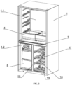
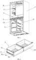
- An integrated refrigerator includes a cabinet 1, a first storage compartment 1.1 and a second storage compartment 1.2 vertically distributed are provided in the cabinet 1, the first storage compartment 1.1 and the second storage compartment 1.2 are separated by a partition 3, and the cabinet 1 is further provided with a cabinet door for closing the first storage compartment 1.1 and the second storage compartment 1.2, where the first storage compartment 1.1 is a fresh zone, and the second refrigerating compartment is a cold storage zone.
- One or a plurality of upper drawers 4 are provided in the first storage compartment 1.1, the plurality of upper drawers 4 can be arranged and distributed in a vertical direction, and the plurality of upper drawers 4 can also be arranged and distributed in a horizontal direction.
- a baffle 6 is provided between two adjacent upper drawers 4, and the baffle 6 divides the upper drawers 4 in different columns to achieve dry-wet separation, which is convenient for users to store articles.
- one or more lower drawers 5 are vertically arranged in the second storage compartment 1.2.
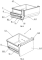
- the upper drawer 4 includes a first body 4.1 and a first stopper 4.2, the first stopper 4.2 is detachably snap-fitted to a front end of the first body 4.1, and an upper handle 4.3 is provided at a lower portion of the upper drawer 4. More preferably, the upper handle 4.3 is arranged at a lower edge of the first stopper 4.2.
- the lower drawer 5 includes a second body 5.1 and a second stopper 5.2, the second stopper 5.2 is detachably snap-fitted to a front end of the second body 5.1, and a lower handle 5.3 is provided at an upper portion of the lower drawer 5.
- the lower handle 5.3 is arranged at an upper edge of the second stopper 5.2, so that the upper handle 4.3 and the lower handle 5.3 are both close to the partition 3.
- the upper handle 4.3 is arranged at the lower end of the upper drawer 4, so that the upper handle 4.3 of the upper drawer 4 located in the first storage compartment 1.1 is located below and is at a position adapted to the user's forehand, so that the user can easily lift up or hold up the upper drawer 4 containing articles, thereby facilitating pushing and pulling of the upper drawer 4.
- the lower handle 5.3 is arranged at the upper end portion of the lower drawer 5, so that the position of the lower handle 5.3 is closer to the upper portion compared to the conventional design, so that the user can reduce the degree of bending during use, especially for the lower drawer 5 at the bottom of the second storage compartment 1.2, and the user can also apply an obliquely upward pulling force to the lower drawer 5 when pulling out the lower drawer 5. That is, lifting up the lower drawer 5 reduces the contact area between the lower drawer 5 and the cabinet 1, thereby facilitating the pulling out of the lower drawer 5.
- a guide slide rail 7 corresponding to the rollers 11 is provided in the cabinet 1
- the guide slide rail 7 is provided with a guide groove 8
- a lower side wall of the guide groove 8 includes a smooth section 8.1, a V-shaped section 8.2 and a forward-tilting section 8.3 provided in sequence, and a lowest point of the V-shaped section 8.2 is higher than a lowest point of the forward-tilting section 8.3.
- a limiting strip 10 is provided on both sides of the upper drawer 4 and the lower drawer 5, the limiting strip 10 is inserted into the corresponding guide groove 8, the limiting strip 10 is provided with a stop block 10.1 matched with the rotating wheel 9 and protruding downward, and the stop block 10.1 is close to the roller 11.
- the guide slide rails 7 are arranged on both sides of the baffle 6 between two adjacent upper drawers 4, thus facilitating sliding of the corresponding upper drawer 4.
- the downward inclined forward-tilting section 8.3 allows the rollers 11 at the front end of the upper drawer 4 or the lower drawer 5 put in place to have a downward movement tendency under the action of gravity, preventing the upper drawer 4 or the lower drawer 5 from directly slipping off when shaking.
- the V-shaped section 8.2 can also play a buffering role and a limiting role, that is, effectively preventing the user from directly pulling out the drawer with excessive force and providing a pause buffer zone.
- the guide slide rail 7 is provided with a rotating wheel 9 matched with the upper drawer 4 or the lower drawer 5, the rotating wheel 9 is rotatably arranged at a front end of the guide slide rail 7, and the rotating wheel 9 protrudes from a lower side wall of the guide groove 8.
- the rotating wheel 9 protruding from the lower side wall of the guide groove 8 can play a load-bearing role for the upper drawer 4 or the lower drawer 5, and is convenient for users to push and pull the drawers due to rotatable nature of the rotating wheel 9.
- a sterilizing device is provided in the first storage compartment 1.1, the sterilizing device includes an ion generator 12, and the ion generator 12 is fixedly arranged at the top of the first storage compartment 1.1.
- the first storage compartment 1.1 is sterilized by negative ions generated by the ion generator 12.
- a wine cabinet 13 may be further provided in the cabinet 1, and a see-through window 14 is provided on a door 2 corresponding to the wine cabinet 13.
- the wine cabinet 13 and the second storage compartment 1.2 are arranged side by side, and the wine cabinet 13 and the second storage compartment 1.2 are divided into zones by a vertical dividing plate 15.
- the wine cabinet is provided with a plurality of horizontal shelves 16 in the vertical direction, the horizontal shelves 16 are detachably matched with the cabinet 1, and the horizontal shelves 16 are further provided with a plurality of placing openings 17 having a narrow width, so that bottle bodies of the wine bottles can be placed at the placing openings 17.
Landscapes
- Engineering & Computer Science (AREA)
- Chemical & Material Sciences (AREA)
- Combustion & Propulsion (AREA)
- Physics & Mathematics (AREA)
- Mechanical Engineering (AREA)
- Thermal Sciences (AREA)
- General Engineering & Computer Science (AREA)
- Drawers Of Furniture (AREA)
- Refrigerator Housings (AREA)
Applications Claiming Priority (2)
| Application Number | Priority Date | Filing Date | Title |
|---|---|---|---|
| CN202221057754.7U CN217764051U (zh) | 2022-04-29 | 2022-04-29 | 一种集成式冰箱 |
| PCT/CN2023/091422 WO2023208159A1 (zh) | 2022-04-29 | 2023-04-28 | 一种集成式冰箱 |
Publications (2)
| Publication Number | Publication Date |
|---|---|
| EP4517228A1 true EP4517228A1 (de) | 2025-03-05 |
| EP4517228A4 EP4517228A4 (de) | 2026-04-01 |
Family
ID=83884323
Family Applications (1)
| Application Number | Title | Priority Date | Filing Date |
|---|---|---|---|
| EP23795591.9A Pending EP4517228A4 (de) | 2022-04-29 | 2023-04-28 | Integriertes kühlgerät |
Country Status (3)
| Country | Link |
|---|---|
| EP (1) | EP4517228A4 (de) |
| CN (1) | CN217764051U (de) |
| WO (1) | WO2023208159A1 (de) |
Families Citing this family (1)
| Publication number | Priority date | Publication date | Assignee | Title |
|---|---|---|---|---|
| CN217764051U (zh) * | 2022-04-29 | 2022-11-08 | 宁波韩电电器有限公司 | 一种集成式冰箱 |
Family Cites Families (14)
| Publication number | Priority date | Publication date | Assignee | Title |
|---|---|---|---|---|
| DE8415549U1 (de) * | 1984-05-22 | 1984-09-13 | Varta-Plastic GmbH, 6480 Wächtersbach | Schubkasten-frontplatte |
| US6565169B1 (en) * | 2000-11-03 | 2003-05-20 | Comercial Acros Whirpool, S.A. De C.V. | Double crisper drawer for a refrigerator |
| JP2008180508A (ja) * | 2008-04-23 | 2008-08-07 | Hitachi Appliances Inc | 冷蔵庫 |
| KR102236740B1 (ko) * | 2014-08-07 | 2021-04-06 | 삼성전자주식회사 | 냉장고 |
| CN104236239A (zh) * | 2014-09-11 | 2014-12-24 | 合肥美的电冰箱有限公司 | 冰箱抽屉和冰箱 |
| KR101861279B1 (ko) * | 2015-09-21 | 2018-05-25 | 엘지전자 주식회사 | 냉장고 및 냉장고의 냉기 유량 모니터링 시스템 |
| CN106568267B (zh) * | 2015-10-07 | 2019-12-27 | 日立环球生活方案株式会社 | 冰箱 |
| KR102401642B1 (ko) * | 2017-08-04 | 2022-05-25 | 엘지전자 주식회사 | 냉장고 |
| CN207247709U (zh) * | 2017-08-11 | 2018-04-17 | 沈阳海尔电冰箱有限公司 | 抽屉式冰箱 |
| CN211476429U (zh) * | 2019-12-17 | 2020-09-11 | 珠海格力电器股份有限公司 | 制冷箱体及设有其的制冷设备 |
| CN212842402U (zh) * | 2020-07-01 | 2021-03-30 | 惠而浦(中国)股份有限公司 | 一种带独立储酒间室的t形结构冰箱 |
| KR102303479B1 (ko) * | 2021-04-15 | 2021-09-24 | (주)아모스아인스가구 | 분할 교체 구조로 된 매립형 도어손잡이 |
| CN215983518U (zh) | 2021-11-02 | 2022-03-08 | 青岛聚友橡塑制品有限公司 | 一种冰箱用的蔬菜室抽屉 |
| CN217764051U (zh) * | 2022-04-29 | 2022-11-08 | 宁波韩电电器有限公司 | 一种集成式冰箱 |
-
2022
- 2022-04-29 CN CN202221057754.7U patent/CN217764051U/zh active Active
-
2023
- 2023-04-28 WO PCT/CN2023/091422 patent/WO2023208159A1/zh not_active Ceased
- 2023-04-28 EP EP23795591.9A patent/EP4517228A4/de active Pending
Also Published As
| Publication number | Publication date |
|---|---|
| CN217764051U (zh) | 2022-11-08 |
| EP4517228A4 (de) | 2026-04-01 |
| WO2023208159A1 (zh) | 2023-11-02 |
Similar Documents
| Publication | Publication Date | Title |
|---|---|---|
| EP4517228A1 (de) | Integriertes kühlgerät | |
| CN201476456U (zh) | 制冷设备及其抽屉式吧台门体 | |
| WO2017143864A1 (zh) | 抽屉及使用该抽屉的冰箱 | |
| CN112594995A (zh) | 一种具有推拉抽屉的卧式冷冻展示柜 | |
| CN101231110B (zh) | 具备多门家庭酒吧的电冰箱门 | |
| CN216019971U (zh) | 一种方便存取的智能橱柜 | |
| US20220349647A1 (en) | Refrigerator and method for adjusting a lid of a drawer in a refrigeration compartment | |
| CN201550986U (zh) | 一种冷藏柜台柜 | |
| WO2021196695A1 (zh) | 冰箱 | |
| CN213849751U (zh) | 轨道式重力回归移门冷藏展示柜 | |
| KR100677983B1 (ko) | 냉장고 서랍 인출입구조 | |
| CN204648808U (zh) | 可侧面开门的冰箱 | |
| CN221526980U (zh) | 一种带有抽拉补货装置的四门冷柜 | |
| CN202675780U (zh) | 一种带有抽屉的冰箱门 | |
| CN219756754U (zh) | 一种冰柜的保温门板 | |
| CN218571741U (zh) | 一种红酒恒温存储柜 | |
| CN219264658U (zh) | 一种带补给仓的冰激凌冷柜 | |
| CN220250423U (zh) | 一种移门冷柜 | |
| CN223503894U (zh) | 一种可推拉收纳抽屉 | |
| CN216822366U (zh) | 一种方便取餐的洁净取餐柜 | |
| CN221060028U (zh) | 一种柜式拉篮 | |
| CN214665451U (zh) | 一种用于餐饮的冷冻柜 | |
| CN214892048U (zh) | 一种新型多层冷冻柜 | |
| KR101269831B1 (ko) | 멀티도어 홈바가 구비된 냉장고도어 | |
| CN111380296A (zh) | 一种冰箱 |
Legal Events
| Date | Code | Title | Description |
|---|---|---|---|
| STAA | Information on the status of an ep patent application or granted ep patent |
Free format text: STATUS: THE INTERNATIONAL PUBLICATION HAS BEEN MADE |
|
| PUAI | Public reference made under article 153(3) epc to a published international application that has entered the european phase |
Free format text: ORIGINAL CODE: 0009012 |
|
| STAA | Information on the status of an ep patent application or granted ep patent |
Free format text: STATUS: REQUEST FOR EXAMINATION WAS MADE |
|
| 17P | Request for examination filed |
Effective date: 20241126 |
|
| AK | Designated contracting states |
Kind code of ref document: A1 Designated state(s): AL AT BE BG CH CY CZ DE DK EE ES FI FR GB GR HR HU IE IS IT LI LT LU LV MC ME MK MT NL NO PL PT RO RS SE SI SK SM TR |
|
| DAV | Request for validation of the european patent (deleted) | ||
| DAX | Request for extension of the european patent (deleted) | ||
| REG | Reference to a national code |
Ref country code: DE Ref legal event code: R079 Free format text: PREVIOUS MAIN CLASS: F25D0011020000 Ipc: F25D0025020000 |
|
| A4 | Supplementary search report drawn up and despatched |
Effective date: 20260304 |
|
| RIC1 | Information provided on ipc code assigned before grant |
Ipc: F25D 25/02 20060101AFI20260226BHEP Ipc: F25D 11/02 20060101ALI20260226BHEP Ipc: F25D 23/12 20060101ALI20260226BHEP Ipc: F25D 23/06 20060101ALI20260226BHEP |