EP4517401A2 - Telekommunikationsgehäuse und zugehörige komponenten - Google Patents
Telekommunikationsgehäuse und zugehörige komponenten Download PDFInfo
- Publication number
- EP4517401A2 EP4517401A2 EP25153131.5A EP25153131A EP4517401A2 EP 4517401 A2 EP4517401 A2 EP 4517401A2 EP 25153131 A EP25153131 A EP 25153131A EP 4517401 A2 EP4517401 A2 EP 4517401A2
- Authority
- EP
- European Patent Office
- Prior art keywords
- gel
- gel sealing
- block
- cable
- bracket
- Prior art date
- Legal status (The legal status is an assumption and is not a legal conclusion. Google has not performed a legal analysis and makes no representation as to the accuracy of the status listed.)
- Pending
Links
Images


Classifications
-
- G—PHYSICS
- G02—OPTICS
- G02B—OPTICAL ELEMENTS, SYSTEMS OR APPARATUS
- G02B6/00—Light guides; Structural details of arrangements comprising light guides and other optical elements, e.g. couplings
- G02B6/44—Mechanical structures for providing tensile strength and external protection for fibres, e.g. optical transmission cables
- G02B6/4439—Auxiliary devices
- G02B6/444—Systems or boxes with surplus lengths
- G02B6/4441—Boxes
- G02B6/4442—Cap coupling boxes
- G02B6/4444—Seals
-
- G—PHYSICS
- G02—OPTICS
- G02B—OPTICAL ELEMENTS, SYSTEMS OR APPARATUS
- G02B6/00—Light guides; Structural details of arrangements comprising light guides and other optical elements, e.g. couplings
- G02B6/44—Mechanical structures for providing tensile strength and external protection for fibres, e.g. optical transmission cables
- G02B6/4439—Auxiliary devices
- G02B6/444—Systems or boxes with surplus lengths
- G02B6/4441—Boxes
- G02B6/4446—Cable boxes, e.g. splicing boxes with two or more multi fibre cables
- G02B6/44465—Seals
-
- G—PHYSICS
- G02—OPTICS
- G02B—OPTICAL ELEMENTS, SYSTEMS OR APPARATUS
- G02B6/00—Light guides; Structural details of arrangements comprising light guides and other optical elements, e.g. couplings
- G02B6/44—Mechanical structures for providing tensile strength and external protection for fibres, e.g. optical transmission cables
- G02B6/4439—Auxiliary devices
- G02B6/4471—Terminating devices ; Cable clamps
- G02B6/44775—Cable seals e.g. feed-through
-
- H—ELECTRICITY
- H02—GENERATION; CONVERSION OR DISTRIBUTION OF ELECTRIC POWER
- H02G—INSTALLATION OF ELECTRIC CABLES OR LINES, OR OF COMBINED OPTICAL AND ELECTRIC CABLES OR LINES
- H02G15/00—Cable fittings
- H02G15/013—Sealing means for cable inlets
Definitions
- the present disclosure relates generally to sealed telecommunications enclosures.
- Telecommunications systems typically employ a network of telecommunications cables capable of transmitting large volumes of data and voice signals over relatively long distances.
- the telecommunications cables can include fiber optic cables, electrical cables, or combinations of electrical and fiber optic cables.
- a typical telecommunications network also includes a plurality of telecommunications enclosures integrated throughout the network of telecommunications cables. The telecommunications enclosures are adapted to house and protect telecommunications components such as splices, termination panels, power splitters and wavelength division multiplexers.
- the telecommunications enclosures can be re-enterable.
- re-enterable means that the telecommunications enclosures can be reopened to allow access to the telecommunications components housed therein without requiring the removal and destruction of the telecommunications enclosures.
- certain telecommunications enclosures can include separate access panels that can be opened to access the interiors of the enclosures, and then closed to re-seal the enclosures.
- Other telecommunications enclosures take the form of elongated sleeves formed by wrap-around covers or half-shells having longitudinal edges that are joined by clamps or other retainers.
- Still other telecommunications enclosures include two half-pieces that are joined together through clamps, wedges or other structures.
- the method also includes removing the gel block from the gel-block mounting sleeve by moving the gel block along the axis relative to the gel-block mounting sleeve after the gel has been placed in tension.
- the gel can be maintained in tension as the gel block is removed from the gel-block mounting sleeve.
- the gel can be placed in tension by an actuator that is also used to apply axial compressive load to the gel to enhance sealing of the gel within the gel-block mounting sleeve.
- the actuator can include at least one spring or a plurality of springs for applying axial compressive load to the gel in the form of compressive spring pressure.
- the gel can define at least one axially extending cable sealing port. In any of the above examples, the gel can define a plurality of axially extending cable ports. In any of the above examples, the gel block can include a plurality of individual gel sealing modules that cooperate to define the gel block. In any of the above examples, the actuator can include inner and outer pressurization structures between which the gel block is pressurized during sealing. In any of the above examples, the gel sealing modules can be attached to inner and outer pressurization structures of an actuator by snap-fit connections capable of transferring tensile load from the pressurization structures to the gel sealing modules. In certain examples, the snap-fit connections can be made by snap-fit interface components which snap together in an axial orientation.
- the gel sealing modules can be individually and separately removable from between the pressurization structures and at least the plurality of the removable gel sealing modules are cable sealing modules each including: at least first and second gel portions that meet at a separable interface which at least one cable port is defined, the first and second gel portions being capable of being separated from one another when the cable sealing module is not between the pressurization structures to allow a cable to be laterally inserted into the cable port; and end caps between which the cable port extends, the end caps each including first end cap portions attached to opposite ends of the first gel portion and second end cap portions attached to opposite ends of the second gel portion, the first and second end cap portions separating from one another when the first and second gel portions are separated from one another.
- the end caps can include snap-fit structures for coupling in a snap-fit connection with the pressurization structures.
- the housing can include a dome coupled to a base, wherein the gel-block mounting sleeve is defined within the base.
- the base can include a first end that couples to the dome and an opposite second end, and the gel sealing block can be inserted into the gel-block mounting sleeve through the second end of the base.
- the pressurization structures can include inner and outer pressurization structures, wherein the inner pressurization structures coupled to an anchoring bracket that is carried with the inner pressurization structure when the gel sealing block is inserted into and remove from the base, wherein the anchoring bracket can be axially inserted into the base with the gel sealing block when in a first rotational position relative to the base, and wherein once the gel sealing block and the anchoring bracket have been inserted into the base, the gel sealing block and the anchoring bracket can be rotated relative to the base to a second rotational position where the anchoring bracket is axially affixed within the base.
- the anchoring bracket is prevented from rotating from the second rotational position back to the first rotational position by a fastener, or a snap-fit structure, or a clip, or a pivoting latch, or a slide latch, or other type of latch, or other structure.
- fiber optic organizers coupled to the anchoring bracket is carried with the gel sealing unit during insertion into the base, the fiber optic organizer preferably including a plurality of pivotal fiber management trays such as splice trays.
- a further aspect of the present disclosure relates to a gel sealing unit including a gel sealing block and an actuator capable of applying compressive load to the gel sealing block during sealing.
- the actuator includes pressurization structures between which the gel sealing block mounts.
- the actuator includes a trigger arrangement for transferring compressive load to the pressurization structures. At least one of the pressurization structures is axially moved along a first axis relative to the other of the pressurization structures when the trigger arrangement is actuated.
- the trigger arrangement includes a handle that is rotated about a second axis angled relative to the first axis to cause relative movement between the pressurization structures along the first axis.
- the first and second axes are perpendicular.
- trigger arrangement can include an angled gear arrangement for transferring torque from the handle to a rotatable component of the trigger arrangement that rotates about the first axis.
- the angled gear arrangement can include angled bevel gears.
- the angled bevel gears that include right angle bevel gears.
- inventive aspects can relate to individual features and to combinations of features. It is to be understood that both the forgoing general description and the following detailed description are exemplary and explanatory only and are not restrictive of the broad inventions and inventive concepts upon which the examples disclosed herein are based.
- Sealing can include sealing of any cables routed through the cable ports defined by the gel sealing block 40, and can also include peripheral sealing 46 defined between a radially outwardly facing gel surface 41 of the gel sealing block 40 and a radially inwardly facing surface 43 of the gel-block mounting sleeve 44.
- the peripheral sealing can be also called a circumferential sealing can extend circumferentially around the gel sealing block 40.
- aspects of the present disclosure relate to a gel sealing unit 38 which is configured to be capable of applying compressive spring load to the gel sealing block 40 to effect sealing, and also capable of applying tensile load to the gel sealing block 40 to cause the gel sealing block 40 to radially constrict such that adhesion between the outer surface of the gel sealing block 40 and the inner surface of the gel-block mounting sleeve 44 is broken or weakened. In this way, removal of the gel sealing unit 38 from the base 26 is facilitated.
- the fiber manager 36 includes a fiber management tower 50 capable of pivotally supporting a plurality of fiber management trays 61 (one tray is shown at Figures 38-43 , but typically a plurality of stacked and overlaid pivotal trays are provided at opposite sides of the fiber management tower 50).
- sets of fiber management trays can be pivotally mounted in a stacked relationship on opposite first and second major sides 51, 53 of the fiber management tower 50.
- the trays can be snapped into receptacles 63 at the major sides 51, 53 of the tower 50.
- the fiber management trays can be adapted to hold fiber optic components such as fiber optic splices, wavelength division multiplexers, passive optical splitters, and the like.
- fiber routing to the trays can be provided at opposite minor sides 54, 55 of the tower 50.
- the fiber management tower 50 can include a lower support extension 56 (e.g., a projection) that couples to an anchoring bracket 60 configured to be locked or fixed within an interior of the base 26.
- the anchoring bracket 60 can also be coupled to the gel sealing unit 38.
- the anchoring bracket 60 can provide a means for axially fixing/supporting the entire telecommunications assembly unit 34 within the interior of the housing 22.
- the anchoring bracket 60 can interconnect with the base 26 by a twist-to-lock configuration.
- cable anchoring units 62 can be mounted on the gel sealing unit 38 and/or to the anchoring bracket 60.
- the cable anchoring units 62 can mount within/to intermediate adapters 64 that attach to the gel sealing unit 38 and/or the anchoring bracket 60 by means such as a snap-fit connection.
- the adapter 64 can be configured to receive a plurality of cable anchoring units 62, or can be configured to receive single cable anchoring units. It will be appreciated that different styles and types of cable anchoring units 62 can be fitted in the adapter 64 so as to be compatible with different type sizes and types of cables routed through the gel sealing unit 38. In other examples, cable anchoring units 62 may be mounted directly to the anchoring bracket 60 without the use of intermediate adapters 64.
- the anchoring bracket 60 can include snap-fit structures, hooks, tabs, rails, slot openings, or other structures for allowing adapters and/or cable anchoring structures and/or adapters to be readily attached to the anchoring bracket 60.
- the anchoring bracket 60 can have a spoked configuration with a plurality of arms that project radially outwardly from a central hub.
- pressurization structures of the actuator 42 can also have a spoked configuration with arms that project radially outwardly from the central hub.
- curved slots 69b on the opposite side of the mid-plane MP are configured to curve toward the minor side 55 of the tower 50 as the slots extend upwardly from bottom ends 71 to top ends 73 of the slots.
- an overall shape of the body of the tube mount 66 is curved along curves along a curvature 75 that extends about a central axis 79 of the base 26. The curvature 75 extends along a length L of the body, and the holders 69 are spaced along the length L.
- Figures 51-60 show an alternative tube mount 166 having an overall body shape that is curved along curves along a curvature 175 that extends about a central axis 79 of the base 26.
- the curvature 175 extends along a length L of the body, and tube holders 169 are spaced along the length L.
- the length L extends across a width of the corresponding major side of the tower 50.
- the tower 50 can also be referred to as a tray mount.
- Tube mount 166 can be positioned at the bottom of each of the major sides 51, 53.
- the tube holders 169 are depicted as closed channels.
- the closed channels can be defined by flexible arms 171 that can be flexed apart to allow tubes to be inserted in the channels.
- the inner and outer pressurization structures 201, 202 are forced apart from one another by a trigger arrangement of the actuator 42, tensile load is applied to the gel block 40 through the snap-fit interfaces.
- snap-fit interface are preferred, other types of interfaces capable of transferring tensile load can also be used.
- the end caps and the pressurization structures can have mating rails and channels that slide together (e.g., in a radial direction) or like structures.
- Figures 81 and 82 show an alternative gel sealing unit 1038 having the same configuration as the gel sealing unit 38 except gel sealing modules are attached to the actuation structure by an interface arrangement including intermating rails and grooves capable of transferring tensile loads from the actuator to the gel sealing modules.
- the depicted gel sealing module 1090 includes end caps with rails 710 that fit within corresponding channels 712 defined by inner and outer pressurization structures 1201, 1202.
- the gel sealing modules 1090 are loaded between the pressurization structures 1201, 1202 by inserting the gel sealing modules 1090 inwardly in a radial direction toward a central axis of the gel sealing unit 1038.
- Each of the gel sealing modules 1090 also includes two flexible latches 714 for preventing the gel sealing modules 1090 from being radially withdrawn from between the pressurization structures 1201, 1202.
- the flexible latches 714 are integrally formed with end caps of the gel sealing modules 1090.
- the flexible latches 714 have a cantilevered configuration.
- the flexible latches 714 are integrated with the end caps of the gel sealing modules 1090 that are positioned adjacent to the inner pressurization structure 1201.
- the inner pressurization structure 1201 can include catches 716 adjacent the outer perimeter of the inner pressurization structure 1201 that are adapted to engage with the flexible latches 714 when the gel sealing modules 1090 are fully inserted into the gel sealing unit 1038.
- the flexible latches can be provided at the end caps corresponding to the outer pressurization structure 1202 and the outer pressurization structure 1202 can include corresponding catches. By flexing the flexible latches 714 toward one another, the flexible latches 714 can disengage from their corresponding catches 716 to allow the gel sealing modules 1090 to be removed from the gel sealing unit.
- gel sealing modules are selected to populate the gel block based on the types and sizes of cables desired to be routed into the enclosure through the gel block.
- a gel sealing module compatible with the cable is selected and a cable anchoring unit compatible with the cable and the selected gel sealing module is also selected.
- the inside radial portion (e.g., gel portion 204) of the gel sealing module is then snapped into the actuator between the pressurization structures, which are in an open orientation in which the pressurization structures are axially far enough apart to allow for insertion of the inside radial portion.
- the cable is then attached to the selected cable anchor which is then secured to the anchoring bracket 60.
- the gel sealing unit 38 can include the gel sealing block 40 and the actuator 42 capable of applying compressive load to the gel sealing block 40 to provide or enhance sealing.
- the actuator includes the inner and outer pressurizations structures 201, 202 between which the gel sealing block 40 mounts.
- the pressurization structures 201, 202 can have a spoked configuration with radial arms on which the snap-fit collars 218 are positioned (see Figure 21B ).
- the actuator 42 includes a trigger arrangement 220 (see Figures 14-30 ) for transferring compressive load to the pressurization structures 201, 202.
- the trigger arrangement 220 includes a threaded first shaft 222 that extends along a first axis 224 along which the outer pressurization structure 202 can axially move to apply the compressive load to the gel sealing block 40.
- the trigger arrangement 220 includes a nut 226 threaded on the shaft 222.
- the nut 226 is rotatable about the first axis 224 relative to the outer pressurization structure 202 and is axially fixed relative to the outer pressurization structure 202.
- axially fixed it is generally meant that the parts that are axially fixed relative to one another are coupled or connected so as to generally move axially together as a unit.
- an outer annular grove 229 surrounding the nut 226 is snapped into a snap-fit sleeve 227 (see Figure 21A ) of the outer pressurization structure 202 to axially lock or fix the nut 226 in place relative to the outer pressurization structure while allowing the nut to turn/rotate relative to the outer pressurization structure 202.
- the nut 226 is integrated or coupled to a handle 228 for turning the nut 226 relative to the outer pressurization structure 202 and the threaded first shaft 222.
- the trigger arrangement 220 also includes a pressurization structure mount 230 for mounting the inner pressurization structure 201.
- the mount 230 can include a mounting sleeve 231 having an outer circumferential surface against which a radially inwardly facing gel surface of the gel block 40 seals when pressurized.
- the inner pressurization structure 201 includes a plurality of separate pressurization sections 232 that are independently slidable relative to the mounting sleeve 231 along the first axis 224.
- the pressurization sections 232 can include webs 234 that slide within slots 236 at an upper end of the mounting sleeve 231.
- the slots 236 have closed lower ends 238 that engage the webs 234 function as positive stops when the trigger arrangement 220 is used to tension the gel block 40.
- the pressurization sections 232 each include two arms carrying collars 218 for snapping together with the upper pins 214 of the gel modules.
- the trigger arrangement 220 including separate springs 240 corresponding to each of the separate pressurization sections 232.
- the spring 240 are captured between first spring stops 242 on the pressurizations sections 232 and second spring stops 244 on the anchor bracket 60 (see Figure 12 ).
- the anchor bracket 60 is fixed to a top end of the mounting sleeve 231 by fasteners or other means.
- the spring 240 fit within vertical bores 246 defined by the pressurization structures 232.
- the threaded first shaft 222 has an upper end 250 that is axially and rotatably fixed relative to the mounting sleeve 231.
- the sleeve 231 defines a T-shaped slot 252 that receives a T-shaped flange 254 at the upper end 250 of the shaft 222.
- the flange 254 can snap within the slot 252.
- the gel sealing block 40 is coupled to the inner and outer pressurization structures 201, 202 by a coupling that allows the inner and outer pressurization structures to apply a tension load to the gel sealing block (e.g., the snap-fit interface described above or other type of interface).
- the gel sealing block 40 includes the plurality of individual gel sealing modules 90 that cooperate to define the gel block 40 with each gel sealing module 90 corresponding to one of the separate pressurization sections 232 of the inner pressurization structure 201.
- the bracket 60 is carried with the sealing unit 38 and the remainder of the telecommunications assembly unit 34.
- the bracket moves through the base 26 and is preferably oriented in a first rotational position relative to the base.
- the base includes a bracket connection interface 300 near the first end of the base.
- the bracket 60 can be rotated relative to a central axis of the base to move the bracket 60 from the first rotational position to a second rotational position in which the bracket 60 engages the connection interface 300 and is axially fixed relative to the base 26.
- portions of the bracket 60 can be captured between upper and lower flanges or other retainers coupled to the base.
- the slide member 756 allows the dome 24 to be installed at the fist end 28 of the base 26 when the slide member 756 is in the anchor bracket retention position.
- the slide member 756 prevents the anchor bracket from being rotated from the second rotational position to the first rotational position when the slide member 756 is in the anchor bracket retention position.
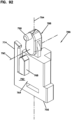
- the bracket blocking projection 768 slides along the inner slot 766 and the dome blocking projection 772 slides along the outer slot 770 as the slide member 756 moves between the dome blocking position (see Figures 86 and 88 ) and the bracket retention position (see Figures 87 and 91 ).
- the slide member 756 includes a flexible latch 774 that engages a catch 776 of the mounting structure 760 provided inside the base 26.
- the flexible latch 774 engages the catch 776 via a snap-fit connection to retain the slide member 756 within the receptacle 762 while concurrently allowing the slide member 756 to slide along the slide orientation 757 between the dome blocking position and the bracket retention position.
- the first end 28 of the base 26 defines the circumferential groove 75 for receiving an end of the dome 24.
- the dome blocking projection 772 is positioned within the circumferential groove 750 so as to provide an obstruction that prevents the bottom end of the dome from being inserted into the groove 750.
- the dome blocking projection 768 is recessed relative to the circumferential groove 750 such that the circumferential groove 750 is not obstructed and the end of the dome 24 can readily be inserted therein.
- bracket blocking projection 768 of the slide member 756 opposes a stop surface 778 of a flange 780 of one of the radial arms 782 to prevent the anchor bracket 60 from being rotated relative to the base 26 from the second rotational position to the first rotational position.
- bracket blocking projection 768 is offset from the flange 780 (e.g., positioned above as shown at Figure 86 ) so as to not interfere with the ability to rotate the bracket 60 between the first and second rotational positions.
- the bracket blocking projection 768 can have a lower end having angled surfaces 784 that facilitate moving the bracket blocking portion 768 past the flange 780 when the slide member 756 is moved from the dome blocking position to the bracket blocking position.
- the assembly prevention arrangement 740 includes a linkage 786 which includes both the slide member 756 and a pivot link 788 pivotally connected to the slide member 756 at a pivot axis 790.
- the pivot link 788 includes a main link body 792 that pivots about the pivot axis 790 between a first pivot position (see Figures 86 and 92 ) and a second pivot position (see Figures 87 and 93 ) as the slide member is moved between the dome blocking position (see Figure 86 ) and the bracket retention position (see Figure 87 ).
- the pivot link 788 is in the first pivot position when the slide member 756 is in the dome blocking position and the pivot link 788 is in the second pivot position when the slide member 756 is in the bracket retention position.
- the main link body 792 has a lengthwise axis 794 that passes through the pivot axis 790.
- the lengthwise axis 794 is parallel to the slide orientation 757 of the slide member 756 such that the pivot link 788 prevents the slide member 756 from being manually moved along the slide orientation 757 by pressing on the slide member 756.
- the pivot link 788 also includes an inwardly projecting pin 796.
- the pin 796 is positioned such that when the anchoring bracket 60 is rotated from the first rotational position to the second rotational position, the anchoring bracket contacts the inwardly projecting pin 796 causing the pivot link 788 to pivot from the first pivot position toward the second pivot position thereby causing the slide member 756 to move from the dome blocking position toward the anchor bracket retention position.
- the flange 780 of the arm 782 of the anchoring bracket 60 engages the inwardly projecting pin 796 to initiate movement of the pivot link 788 from the first pivot position toward the second pivot position.
- the pivot link 788 includes a pivot element 798 through which the pivot axis 790 extends.
- the pivot element 798 has a polygonal cross-sectional shape. In one example, the polygonal cross-sectional shape is square, but other shapes can be used as well.
- the slide member 756 has a pivot receiver 800 that receives the pivot element 798.
- the pivot receiver 800 is best shown at Figures 97 and 98 .
- the pivot receiver 800 has a polygonal cross-sectional shape that matches the polygonal cross-sectional shape of the pivot element 798.
- the pivot element 798 pivots within the pivot receiver 800 when the pivot link 788 is pivoted about the pivot axis 790.
- the pivot receiver 800 has a resilient construction that elastically deforms or flexes to accommodate pivotal movement between the pivot element 798 and the pivot receiver 800.
- the matching polygonal cross-sectional shapes of the pivot element 798 and the pivot receiver 800 combined with the resilient, elastic construction of the pivot receiver 800 require a predetermined force to be applied to the pivot link 788 to cause the pivot receiver 800 to elastically flex a sufficient amount to allow the pivot link 788 to be moved from the first pivot position to the second pivot position and vice versa.
- the pivot receiver 800 retains the pivot link in the first pivot position and the second pivot position until the predetermined force is applied to the linkage so as to overcome the elastic retention force provided by the pivot receiver.
- the pivot link 788 pivots about 90 degrees between the first pivot position and the second pivot position.
- the pivot element 798 and the pivot receiver 800 provide an over-the-center biasing arrangement that elastically biases the pivot link 788 toward the first pivot position when the pivot link 88 is rotationally closer to the first pivot position than the second pivot position and that biases the pivot link 788 toward the second pivot position when the pivot link is rotationally closer to the second pivot position than the first pivot position.
- the center position coincides with the pivot link having pivoted about 45 degrees between the first pivot position and the second pivot position.
- Figures 61-67 show one of the cable anchor unit adapters 64 for receiving a plurality of cable anchor units 62.
- the adapter 64 includes a rear snap-fit interface 400 including a flexible latch 402 for engaging a mating interface on the bracket 60.
- the adapter 64 includes receptacles for receiving cable anchors 62.
- the adapter also include rear reinforcing ribs 404 that fit within slots 406 defined by the pressurization sections 232 of the inner pressurization structure 201.
- Figure 68-71 show an example cable anchoring unit 420 including a rectangular main body 422, a first cradle 424 for clamping a cable jacket with a metal band, a second cradle 426 for clamping a cable shield with a metal band, a strength member or conductor anchor 428 for wrapping aramid yarn of a cable or for securing a rigid member such as a metal member or a glass reinforced polymer rod.
- An electrical contact 430 is provided at the anchor 428 for grounding purposes. The contact is connected to a grounding screw 432.
- a cable shield secured at the second cradle 426 can also be connected to the grounding screw, which is between the cradle 426 and the anchor 428.
- Strap tighteners 434 can be provided within the cradles 424, 426 for receiving the ends of straps inserted though slits 436 in the cradles 424, 426.
- Fasteners 438 secure the ends of the straps in slots 440 in the tighteners 434.
- Fasteners 442 move the tighteners downwardly away from the cradles to tighten the straps.
- the anchoring unit 420 can be secured to a bracket or other structure via an intermediate adapter or other structure that may include snap-fit features.
- Figures 72 and 73 show an alternative cable anchoring unit which is the same as the cable anchoring unit 420, except a rear side of the main body has been equipped with an integrated snap-fit structure for attaching the cable anchoring unit directly to an anchor bracket or other structure without the need for an adapter.
- the snap-fit structure can include a snap-fit latch, tab, arm or like structure.
- the rear interface can also include stabilization ribs that can engage an anchoring bracket or a pressurization structure (e.g., the ribs can fit within slots in the inner pressurization structure such as slots 406 defined by the pressurization sections 232 of the inner pressurization structure 201).
- Figures 99 and 100 show a configuration where cable anchoring units or cable anchoring unit adapters can be mounted directly to the anchoring bracket at a position completely above the gel sealing unit 38.
- the cable anchoring unit adapters and/or the anchoring units do not engage any portion of the gel sealing unit 38 and are instead secured to and stabilized by the bracket alone.
- the cable anchoring units and/or the cable anchoring unit adapters are secured to a hub of the bracket by an interface that includes: a) a groove and rail configuration for stabilizing the cable anchoring device relative to the bracket and for allowing the cable anchoring device to be loaded into the bracket by radially inserting the cable anchoring device into the bracket; and b) a snap-fit connection for releasably retaining the cable anchoring device in an inserted position relative to the bracket.
- a bracket 1060 is shown having a hub 810 and a plurality of radial arms 812 that project radially outwardly from the hub 810.
- the bracket 1060 also includes a reinforcing ring 814 that couples to the arms 812 at an intermediate location between the hub 810 and outer ends 816 of the radial arms 812.
- Cable anchoring devices 820 of the type previously described herein are mounted at an upper side of the hub.
- the mounting locations are located circumferentially between the arms 812 and are provided at the hub 810.
- Each of the mounting locations can include a snap-fit catch 822 and stabilizing grooves 824.
- the cable anchoring device 820 can include rails 826 that fit within the grooves 824 for stabilization, and a snap-fit latch 828 between the rails 826 that fits within the snap-fit catch 822.
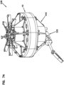
- Figures 74-79 show another gel sealing unit 538 that can be used with an enclosure such as the enclosure of Figure 1 .
- the gel sealing unit 538 includes the gel sealing block 40 an actuator 542 capable of applying compressive load to the gel sealing block during sealing.
- the actuator 542 includes inner and outer pressurizations structures 501, 502 between which the gel sealing block 40 mounts.
- the actuator 542 includes a trigger arrangement 520 for transferring compressive load to the pressurization structures.
- the trigger arrangement 520 includes a threaded first shaft 522 that extends along a first axis 524 along which the outer pressurization structure 502 can axially move to apply the compressive load to the gel sealing block 40.
- the threaded first shaft 522 including a head 523 that mounts within a pocket 525 defined by the inner pressurization structure 501.
- the head 523 is axially slidable within the pocket 525 along the first axis 524 relative to the inner pressurization structure 501, but is prevented from rotating relative to the inner pressurization structure 501 about the first axis 514 (e.g., by one or more opposing flats or other ant-rotation features).
- the trigger arrangement 520 also including a spring 540 mounted on the threaded first shaft 522 and captured between the head 523 of the threaded first shaft 522 and a spring stop 527 that is axially fixed relative to the inner pressurization structure 501.
- the threaded first shaft 522 extends through the spring stop 527 and is rotatable relative to the spring stop 527 without threadingly engaging the spring stop 527.
- the trigger arrangement 520 also includes a nut 541 threaded on the threaded first shaft 522.
- the nut 541 is rotatable relative to the outer pressurization structure 502 while also being axially fixed relative to the outer pressurization structure 502 such that the outer pressurization structure 502 is carried with the nut 541 axially along the first axis 524 when the nut 541 is threaded on the threaded first shaft 522.
- the trigger arrangement 520 further including a first bevel gear 543 integrated with or coupled to the nut 541.
- the trigger arrangement 520 also including a handle 545 mounted on a second shaft 547 that extends along a second axis 549 angled relative to the first axis 524.
- the second shaft 547 is coupled to a second bevel gear 551 that intermeshes with the first bevel gear 543 such that when the handle 545 is turned about the second axis 549 the second bevel gear 551 turns the nut 541 about the threaded first shaft 522 causing axial movement of the nut 541 and the outer pressurization structure 502 relative to the first threaded shaft 522.
- the shaft 522 When the nut 541 is threaded in a first rotational direction about the shaft 522, the shaft 522 is moved axially in a first direction along the first axis 524 relative to the nut 541 and the outer pressurization structure 502 causing the head 523 of the shaft 522 to slide axially within the pocket 525 of the inner pressurization structure 502 in the first direction along the first axis 524 toward the spring stop 527 causing the spring 540 to be compressed between the head 523 and the spring stop 527 which causes the threaded first shaft 522 to be placed in tension such that spring compression load is axially applied to the gel sealing block 40 between the inner and outer pressurization structures 501, 502.
- the angled configuration of the handle allows the handle to be readily accessed even if the gel block is densely packed with cables.
- the gel sealing block 40 is preferably coupled to the inner and outer pressurization structures 501, 502 by a coupling of the type described above that allows the inner and outer pressurization structures 50, 502 to apply a tension load to the gel sealing block 40.
- the shaft 522 is moved axially in a second direction along the first axis 524 relative to the nut 541 and the outer pressurizations structure 502 causing the head 523 of the shaft 522 to slide axially within the pocket 525 of the inner pressurization structure 501 in the second direction along the first axis 524 away from the spring stop 527 as the spring is de-compressed.
Landscapes
- Physics & Mathematics (AREA)
- General Physics & Mathematics (AREA)
- Optics & Photonics (AREA)
- Light Guides In General And Applications Therefor (AREA)
- Transmitters (AREA)
- Casings For Electric Apparatus (AREA)
- Insertion, Bundling And Securing Of Wires For Electric Apparatuses (AREA)
- Executing Machine-Instructions (AREA)
- Cable Accessories (AREA)
Applications Claiming Priority (4)
| Application Number | Priority Date | Filing Date | Title |
|---|---|---|---|
| US201762524240P | 2017-06-23 | 2017-06-23 | |
| US201862622644P | 2018-01-26 | 2018-01-26 | |
| EP18733602.9A EP3642922B1 (de) | 2017-06-23 | 2018-06-23 | Telekommunikationsgehäuse und zugehörige komponenten |
| PCT/EP2018/066842 WO2018234579A1 (en) | 2017-06-23 | 2018-06-23 | Telecommunications enclosure and related components |
Related Parent Applications (1)
| Application Number | Title | Priority Date | Filing Date |
|---|---|---|---|
| EP18733602.9A Division EP3642922B1 (de) | 2017-06-23 | 2018-06-23 | Telekommunikationsgehäuse und zugehörige komponenten |
Publications (2)
| Publication Number | Publication Date |
|---|---|
| EP4517401A2 true EP4517401A2 (de) | 2025-03-05 |
| EP4517401A3 EP4517401A3 (de) | 2025-04-30 |
Family
ID=62713018
Family Applications (2)
| Application Number | Title | Priority Date | Filing Date |
|---|---|---|---|
| EP25153131.5A Pending EP4517401A3 (de) | 2017-06-23 | 2018-06-23 | Telekommunikationsgehäuse und zugehörige komponenten |
| EP18733602.9A Active EP3642922B1 (de) | 2017-06-23 | 2018-06-23 | Telekommunikationsgehäuse und zugehörige komponenten |
Family Applications After (1)
| Application Number | Title | Priority Date | Filing Date |
|---|---|---|---|
| EP18733602.9A Active EP3642922B1 (de) | 2017-06-23 | 2018-06-23 | Telekommunikationsgehäuse und zugehörige komponenten |
Country Status (6)
| Country | Link |
|---|---|
| US (3) | US11300745B2 (de) |
| EP (2) | EP4517401A3 (de) |
| AU (1) | AU2018287437B2 (de) |
| DK (1) | DK3642922T3 (de) |
| PL (1) | PL3642922T3 (de) |
| WO (1) | WO2018234579A1 (de) |
Families Citing this family (29)
| Publication number | Priority date | Publication date | Assignee | Title |
|---|---|---|---|---|
| MX2020011947A (es) | 2018-05-09 | 2021-01-15 | Afl Telecommunications Llc | Cierres de tapon y bases para los mismos. |
| TWD201180S (zh) * | 2018-10-25 | 2019-12-01 | Alloy Steel Australia Int Pty Ltd | 耐磨板固定裝置之部分 |
| CN109655984B (zh) * | 2019-02-02 | 2023-09-15 | 中天宽带技术有限公司 | 一种螺旋密封式用于相交光缆接续的帽式接头盒 |
| USD923467S1 (en) * | 2019-04-18 | 2021-06-29 | Alvin Buffalo | Wedge anchor removal device |
| EP4032158A4 (de) | 2019-09-20 | 2023-10-11 | CommScope Technologies LLC | Telekommunikationsgehäuse mit behälterstrukturen für o-ringe |
| US11635577B2 (en) * | 2020-01-08 | 2023-04-25 | Clearfield, Inc. | Gasket for a sealed optical fiber terminal |
| MX2021001913A (es) | 2020-02-18 | 2021-08-19 | Bemis Mfg Co | Conjunto de fijacion para bisagra de asiento de inodoro. |
| USD984881S1 (en) * | 2020-02-18 | 2023-05-02 | Bemis Manufacturing Company | Fastening nut |
| US10996414B1 (en) | 2020-03-23 | 2021-05-04 | Afl Telecommunications Llc | Butt closures and bases therefor |
| WO2021198787A1 (en) | 2020-03-30 | 2021-10-07 | CommScope Connectivity Belgium BV | Base interface for a telecommunications closure |
| EP4139729A4 (de) * | 2020-04-20 | 2024-06-05 | CommScope Technologies LLC | Glasfasergehäuse mit fähigkeit zur anpassung und/oder aufrüstung |
| US20230314728A1 (en) * | 2020-08-14 | 2023-10-05 | Commscope Technologies Llc | Fiber optic enclosure with a side cable entrance |
| US12078846B2 (en) | 2020-11-30 | 2024-09-03 | Afl Telecommunications Llc | Butt closures and bases therefor |
| USD972404S1 (en) * | 2021-01-15 | 2022-12-13 | Bemis Manufacturing Company | Fastening nut |
| USD972403S1 (en) * | 2021-01-15 | 2022-12-13 | Bemis Manufacturing Company | Fastening nut |
| US12160069B2 (en) | 2021-04-13 | 2024-12-03 | Corning Research & Development Corporation | Compression mechanisms for cable sealing on closures |
| IT202100021113A1 (it) | 2021-08-04 | 2023-02-04 | Prysmian Spa | Telecommunications enclosure |
| IT202100021098A1 (it) | 2021-08-04 | 2023-02-04 | Prysmian Spa | Telecommunications enclosure |
| EP4160292A1 (de) | 2021-09-30 | 2023-04-05 | Corning Research & Development Corporation | Dichtungssystem für telekommunikationsverschlüsse |
| CN113853072B (zh) * | 2021-10-19 | 2024-01-26 | 威胜能源技术股份有限公司 | 一种数字式管理单元热插拔结构 |
| EP4430440A4 (de) * | 2021-11-08 | 2025-10-08 | Commscope Technologies Llc | Sensor für faseroptische verschlüsse |
| EP4457912A4 (de) * | 2021-12-30 | 2025-12-17 | Commscope Technologies Llc | Dichtungsaktuator mit druckbeaufschlagungsgrenze |
| CN114415304B (zh) * | 2022-01-30 | 2023-10-20 | 华为技术有限公司 | 光缆接头盒以及相关的光缆连接装置 |
| EP4286909A1 (de) * | 2022-06-01 | 2023-12-06 | Corning Research & Development Corporation | Endkappe für einen kabelverschluss |
| DE212023000045U1 (de) * | 2022-07-06 | 2024-01-12 | Yelco Technologies, Sa | Erweiterungsmodul für modulare Schutzvorrichtungen für Systeme zur Organisation von Lichtwellenleitern |
| WO2024076544A1 (en) * | 2022-10-02 | 2024-04-11 | Ppc Broadband, Inc. | Seal assembly for a port of an enclosure that permits a cable terminated with a connector to be inserted into and removed from the port with the connector attached to the cable |
| CN116381876A (zh) * | 2022-12-20 | 2023-07-04 | 浙江超前通信科技股份有限公司 | 一种密封结构及立式光缆接头盒 |
| USD1006610S1 (en) * | 2023-09-06 | 2023-12-05 | Zhongshan Dongfeng Town Xinhao Hardware Factory | Multi-segment rail mounting structural connector |
| CN120103558A (zh) * | 2025-04-30 | 2025-06-06 | 中天宽带技术有限公司 | 光缆接头盒 |
Citations (5)
| Publication number | Priority date | Publication date | Assignee | Title |
|---|---|---|---|---|
| EP0442941B1 (de) | 1988-11-09 | 1995-01-25 | N.V. Raychem S.A. | Dichtungsmaterial und verschlussverfahren und -vorrichtung |
| EP0587616B1 (de) | 1991-06-06 | 1996-07-17 | N.V. Raychem S.A. | Abdichtungsvorrichtung, insbesondere kabelabdichtung |
| US6046406A (en) | 1996-05-15 | 2000-04-04 | Alcatel Cable Interface | Sealed cable joint box |
| WO2014005916A2 (en) | 2012-07-02 | 2014-01-09 | Tyco Electronics Raychem Bvba | Cable sealing unit with multiple sealing modules |
| WO2014095462A1 (de) | 2012-12-18 | 2014-06-26 | Reichle & De-Massari Ag | Kabelkontaktierungswitterungsschutz |
Family Cites Families (19)
| Publication number | Priority date | Publication date | Assignee | Title |
|---|---|---|---|---|
| GB9404396D0 (en) | 1994-03-07 | 1994-04-20 | Raychem Sa Nv | Sealing arrangement |
| TW286371B (de) | 1995-03-31 | 1996-09-21 | Minnesota Mining & Mfg | |
| US6536618B1 (en) * | 2000-10-31 | 2003-03-25 | Hsu-Rong Hwang | Bottle plug |
| US7038137B2 (en) | 2003-06-18 | 2006-05-02 | Preformed Line Products Company | Fiber closure system |
| DE202006006019U1 (de) | 2006-04-11 | 2006-06-14 | CCS Technology, Inc., Wilmington | Dichtungskörper einer Kabelmuffe |
| DE202006006020U1 (de) | 2006-04-11 | 2006-06-14 | CCS Technology, Inc., Wilmington | Dichtungskörper einer Kabelmuffe |
| DK2330706T3 (da) | 2009-12-03 | 2017-08-21 | CommScope Connectivity Belgium BVBA | Geletætningsenhed |
| ES2479617T3 (es) | 2011-05-10 | 2014-07-24 | Tyco Electronics Raychem Bvba | Dispositivo de sellado de cables actuado por una palanca de leva |
| US9081164B2 (en) * | 2011-08-24 | 2015-07-14 | Adc Telecommunications, Inc. | Fiber management panel |
| RU2015100264A (ru) | 2012-07-02 | 2016-08-20 | Тайко Электроникс Рейкем Бвба | Рентерабельный кожух |
| WO2014005919A2 (en) * | 2012-07-02 | 2014-01-09 | Tyco Electronics Raychem Bvba | Seal actuator with actuation level indicator |
| EP2867963A2 (de) | 2012-07-02 | 2015-05-06 | Tyco Electronics Raychem BVBA | Reduzierer für kabelanschlussgrösse |
| CA2901148A1 (en) | 2013-02-19 | 2014-08-28 | Tyco Electronics Raychem Bvba | Re-enterable enclosure and configuration for mounting |
| DE102013114533A1 (de) | 2013-12-19 | 2015-06-25 | Reichle & De-Massari Ag | Dichtmodul |
| US10012814B2 (en) * | 2014-10-01 | 2018-07-03 | Clearfield, Inc. | Optical fiber management |
| US10209473B2 (en) * | 2015-06-19 | 2019-02-19 | Commscope Technologies Llc | Optical termination enclosure |
| MX2019001248A (es) * | 2016-09-07 | 2019-04-25 | Commscope Technologies Llc | Geles anisotropicos de sellado de cable; y metodos para fabricar geles de sellado de cable. |
| EP3589993A1 (de) * | 2017-03-01 | 2020-01-08 | CommScope Connectivity Belgium BVBA | Kabelabdichtung mit mehreren kabeldichtungsmodulen |
| DE102018101790A1 (de) * | 2018-01-26 | 2019-08-01 | Harting Electric Gmbh & Co. Kg | Dichteinsatz |
-
2018
- 2018-06-23 PL PL18733602.9T patent/PL3642922T3/pl unknown
- 2018-06-23 EP EP25153131.5A patent/EP4517401A3/de active Pending
- 2018-06-23 DK DK18733602.9T patent/DK3642922T3/da active
- 2018-06-23 EP EP18733602.9A patent/EP3642922B1/de active Active
- 2018-06-23 AU AU2018287437A patent/AU2018287437B2/en active Active
- 2018-06-23 US US16/626,196 patent/US11300745B2/en active Active
- 2018-06-23 WO PCT/EP2018/066842 patent/WO2018234579A1/en not_active Ceased
-
2022
- 2022-04-11 US US17/717,759 patent/US12153271B2/en active Active
-
2024
- 2024-10-17 US US18/918,764 patent/US20250116835A1/en active Pending
Patent Citations (5)
| Publication number | Priority date | Publication date | Assignee | Title |
|---|---|---|---|---|
| EP0442941B1 (de) | 1988-11-09 | 1995-01-25 | N.V. Raychem S.A. | Dichtungsmaterial und verschlussverfahren und -vorrichtung |
| EP0587616B1 (de) | 1991-06-06 | 1996-07-17 | N.V. Raychem S.A. | Abdichtungsvorrichtung, insbesondere kabelabdichtung |
| US6046406A (en) | 1996-05-15 | 2000-04-04 | Alcatel Cable Interface | Sealed cable joint box |
| WO2014005916A2 (en) | 2012-07-02 | 2014-01-09 | Tyco Electronics Raychem Bvba | Cable sealing unit with multiple sealing modules |
| WO2014095462A1 (de) | 2012-12-18 | 2014-06-26 | Reichle & De-Massari Ag | Kabelkontaktierungswitterungsschutz |
Also Published As
| Publication number | Publication date |
|---|---|
| US12153271B2 (en) | 2024-11-26 |
| AU2018287437B2 (en) | 2023-06-01 |
| US11300745B2 (en) | 2022-04-12 |
| WO2018234579A1 (en) | 2018-12-27 |
| US20250116835A1 (en) | 2025-04-10 |
| EP3642922A1 (de) | 2020-04-29 |
| PL3642922T3 (pl) | 2025-06-23 |
| US20220317402A1 (en) | 2022-10-06 |
| US20200249407A1 (en) | 2020-08-06 |
| AU2018287437A8 (en) | 2020-02-13 |
| EP4517401A3 (de) | 2025-04-30 |
| DK3642922T3 (da) | 2025-05-19 |
| AU2018287437A1 (en) | 2019-12-19 |
| EP3642922B1 (de) | 2025-02-19 |
Similar Documents
| Publication | Publication Date | Title |
|---|---|---|
| US12153271B2 (en) | Telecommunications enclosure and related components | |
| US20240219672A1 (en) | Terminal enclosure with modular aspects and modules for interfacing with the terminal enclosure | |
| US20210356687A1 (en) | Optical termination enclosure with ruggedized self-supporting tethers | |
| US11262520B2 (en) | Connection module for cable seal gel block | |
| US11703651B2 (en) | Cable termination assembly with disengagement prevention structures | |
| CN104272154B (zh) | 用于光纤外壳的缆线锚固系统 | |
| WO2010008718A2 (en) | Telecommunications cable inlet device | |
| EP4130829B1 (de) | Telekommunikationsgehäuse | |
| EP4196834A1 (de) | Glasfasergehäuse mit seitenkabeleingang | |
| EP4130828B1 (de) | Telekommunikationsgehäuse | |
| JP4800085B2 (ja) | 光クロージャ | |
| WO2024238849A1 (en) | Cable closure with sealed ends |
Legal Events
| Date | Code | Title | Description |
|---|---|---|---|
| PUAI | Public reference made under article 153(3) epc to a published international application that has entered the european phase |
Free format text: ORIGINAL CODE: 0009012 |
|
| STAA | Information on the status of an ep patent application or granted ep patent |
Free format text: STATUS: THE APPLICATION HAS BEEN PUBLISHED |
|
| AC | Divisional application: reference to earlier application |
Ref document number: 3642922 Country of ref document: EP Kind code of ref document: P |
|
| AK | Designated contracting states |
Kind code of ref document: A2 Designated state(s): AL AT BE BG CH CY CZ DE DK EE ES FI FR GB GR HR HU IE IS IT LI LT LU LV MC MK MT NL NO PL PT RO RS SE SI SK SM TR |
|
| REG | Reference to a national code |
Ref country code: DE Ref legal event code: R079 Free format text: PREVIOUS MAIN CLASS: G02B0006440000 Ipc: H02G0015013000 |
|
| PUAL | Search report despatched |
Free format text: ORIGINAL CODE: 0009013 |
|
| AK | Designated contracting states |
Kind code of ref document: A3 Designated state(s): AL AT BE BG CH CY CZ DE DK EE ES FI FR GB GR HR HU IE IS IT LI LT LU LV MC MK MT NL NO PL PT RO RS SE SI SK SM TR |
|
| RIC1 | Information provided on ipc code assigned before grant |
Ipc: G02B 6/44 20060101ALI20250326BHEP Ipc: H02G 15/013 20060101AFI20250326BHEP |
|
| STAA | Information on the status of an ep patent application or granted ep patent |
Free format text: STATUS: REQUEST FOR EXAMINATION WAS MADE |
|
| 17P | Request for examination filed |
Effective date: 20251021 |
|
| STAA | Information on the status of an ep patent application or granted ep patent |
Free format text: STATUS: EXAMINATION IS IN PROGRESS |
|
| 17Q | First examination report despatched |
Effective date: 20260225 |