EP4517403A1 - Optique de collecte à mélange de couleurs à fonctionnalité améliorée - Google Patents
Optique de collecte à mélange de couleurs à fonctionnalité améliorée Download PDFInfo
- Publication number
- EP4517403A1 EP4517403A1 EP23194114.7A EP23194114A EP4517403A1 EP 4517403 A1 EP4517403 A1 EP 4517403A1 EP 23194114 A EP23194114 A EP 23194114A EP 4517403 A1 EP4517403 A1 EP 4517403A1
- Authority
- EP
- European Patent Office
- Prior art keywords
- light
- color
- mixing
- lens
- light guide
- Prior art date
- Legal status (The legal status is an assumption and is not a legal conclusion. Google has not performed a legal analysis and makes no representation as to the accuracy of the status listed.)
- Pending
Links
Images


Classifications
-
- G—PHYSICS
- G02—OPTICS
- G02B—OPTICAL ELEMENTS, SYSTEMS OR APPARATUS
- G02B19/00—Condensers, e.g. light collectors or similar non-imaging optics
- G02B19/0033—Condensers, e.g. light collectors or similar non-imaging optics characterised by the use
- G02B19/0047—Condensers, e.g. light collectors or similar non-imaging optics characterised by the use for use with a light source
- G02B19/0061—Condensers, e.g. light collectors or similar non-imaging optics characterised by the use for use with a light source the light source comprising a LED
- G02B19/0066—Condensers, e.g. light collectors or similar non-imaging optics characterised by the use for use with a light source the light source comprising a LED in the form of an LED array
-
- G—PHYSICS
- G02—OPTICS
- G02B—OPTICAL ELEMENTS, SYSTEMS OR APPARATUS
- G02B19/00—Condensers, e.g. light collectors or similar non-imaging optics
- G02B19/0004—Condensers, e.g. light collectors or similar non-imaging optics characterised by the optical means employed
- G02B19/0028—Condensers, e.g. light collectors or similar non-imaging optics characterised by the optical means employed refractive and reflective surfaces, e.g. non-imaging catadioptric systems
-
- F—MECHANICAL ENGINEERING; LIGHTING; HEATING; WEAPONS; BLASTING
- F21—LIGHTING
- F21Y—INDEXING SCHEME ASSOCIATED WITH SUBCLASSES F21K, F21L, F21S and F21V, RELATING TO THE FORM OR THE KIND OF THE LIGHT SOURCES OR OF THE COLOUR OF THE LIGHT EMITTED
- F21Y2113/00—Combination of light sources
- F21Y2113/10—Combination of light sources of different colours
- F21Y2113/13—Combination of light sources of different colours comprising an assembly of point-like light sources
-
- F—MECHANICAL ENGINEERING; LIGHTING; HEATING; WEAPONS; BLASTING
- F21—LIGHTING
- F21Y—INDEXING SCHEME ASSOCIATED WITH SUBCLASSES F21K, F21L, F21S and F21V, RELATING TO THE FORM OR THE KIND OF THE LIGHT SOURCES OR OF THE COLOUR OF THE LIGHT EMITTED
- F21Y2115/00—Light-generating elements of semiconductor light sources
- F21Y2115/10—Light-emitting diodes [LED]
-
- G—PHYSICS
- G02—OPTICS
- G02B—OPTICAL ELEMENTS, SYSTEMS OR APPARATUS
- G02B27/00—Optical systems or apparatus not provided for by any of the groups G02B1/00 - G02B26/00, G02B30/00
- G02B27/09—Beam shaping, e.g. changing the cross-sectional area, not otherwise provided for
- G02B27/0938—Using specific optical elements
- G02B27/0994—Fibers, light pipes
Definitions
- the invention relates to a color-mixing collection optics, which can be used on the one hand for full-color pixels for outdoor display panels for displaying graphics, images and videos over longer distances, but on the other hand also as a full-color light source for general and effect lighting purposes.
- full-color or RGB LEDs have become established in the indoor area, which usually contain three chips in the primary colors red, green and blue in a common housing with a flat, translucent encapsulation, whereby the chip or chip dimensions refer to the luminous area of the semiconductors used. They are available in various sizes, so that high-resolution displays on smaller display panels are also possible. They emit their light directly into the room in the form of a cosine emitter without optics and therefore have a relatively low display brightness, but can be seen very well from close up and from a large observation area.
- the invention relates in its embodiments to that international application WO 2012/068603 (Swarco ), also known as EP 2643717 B1 or PCT/AT2011/000468 published, which is to be regarded as the state of the art and has been thoroughly examined with regard to counter-arguments and objections and the related known publications cited therein, which could also be cited here in the same way, and is of course the closest to this new invention.
- It represents an excellent color mixture for any crystal arrangement, which is achieved by a gapless multiple reflection on the highly polished planes of the light guide ( FIG. 1 , subclaim 10) or main claim in the EP produce a uniformly brightly radiating exit surface (4) on which the focus (F) of the upstream converging lens (5) comes to rest.
- the converging lens is therefore a correspondingly designed rotational body.
- the present invention also uses an RGB or multicolor LED light source, which, however, must meet certain conditions regarding the arrangement, type and size of the chips, which in reality only causes problems in exceptional cases. This results in greater design freedom for the color-mixing optics, which enables more precise and thus allows more efficient, but also more varied adjustment of the resulting light distribution and differs significantly from the known design.
- the converging lens has a light entry surface, a light guide and a converging lens in the same direction as the main light emission direction, it is characterized in that all chips of the LED light source are arranged linearly at close intervals, have the same width dimensions and emission characteristics, that the light guide is limited on both sides of the linear arrangement by symmetrically designed, highly polished reflection planes aligned perpendicularly to it, the distance between which is constant or gradually increases in the direction of the converging lens and whose ends define the exit surface, and is defined transversely by sharp-edged, highly polished connecting surfaces of a different shape, and that the converging lens has a focal point in the cross section in the direction of the linear arrangement, which lies on this exit surface of the light guide, and has a different focal point, or no pronounced focal point at all, or a focal spot, and thus the highly polished lens tip represents a free-form surface.
- the chip width (c) is always understood here as the measurement across the linear arrangement. In other words: if the chips are positioned in a tight linear arrangement and have the same widths and the same radiation characteristics, which is the case with the vast majority of RGB LEDs for video displays, it is sufficient to mix the different colors only in the direction of the linear arrangement, which is achieved by the reflection planes of the light guide arranged on both sides, but no color mixing is necessary in the transverse direction. This means that the connecting surfaces between the reflection planes of the light guide are freed from the mixing-related design as reflection planes and can thus produce a more precisely adjusted or different light distribution in this direction.
- the converging lens contour required for color mixing with a focal point on the light exit surface of the light guide is then only necessary for the lens cross-section in this linear direction; transversely to this, the converging lens can take an independent course, which usually leads to the formation of oval, egg or rod-shaped lens geometries.
- the light distribution across the linear chip arrangement is then achieved by the interaction of the connecting surfaces with the converging lens design in this direction. Because there are significantly more design parameters here than in the linear If the direction of mixing is achieved by means of planes, this creates more and new possibilities for light distribution compared to the known design, especially for new applications that have yet to be developed.
- the requirements for light distribution and the design options for light guides and converging lenses determine how the linear arrangement of the chips in the display product is to be oriented.
- a linear arrangement in a horizontal direction is recommended because the resulting cosine-like light distributions have long been proven and are also recommended by the product standard EN 12966, and some designs have to take the position of the sun into account.
- the light distribution is much more demanding, which is better suited to the free design of the connecting surfaces. can be generated.
- only a horizontal orientation is assumed in order to keep the figure descriptions simple and understandable, but this does not represent any restriction with regard to the orientation of the invention in space; just think of a general use of the system in a full-color flashlight.
- FIG. 1 A and 1 B the basic structure and functionality of the invention in longitudinal and transverse views
- FIG. 2 shows suitable and unsuitable chip arrangements of LED light sources in top view
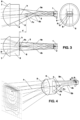
- FIG. 3 an inventive embodiment of an optic in plan, top and side view
- FIG. 4 shows the invention in a clear representation with the generated light distribution
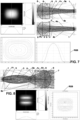
- FIG. 5 the simulated beam path in plan and elevation with representation of the achieved light distribution of the optics in three graphics
- FIG. 6 the achieved light distributions of the individual chips in comparison
- FIG. 7 another application of the invention in plan and elevation with beam path and representation of the achieved light distribution also in three graphics
- FIG. 8 an optic with two light beams in elevation
- FIG. 9 an angled optic in elevation, each with achieved light distributions.
- FIG. 1 A the color-mixing optics can be seen in longitudinal view.
- a just cast LED light source 1 with three linearly adjacent chips in the primary colors red R, green G and blue B sends its light into an entry surface 2 of a light guide 3 located directly in front of it. This is refracted to the vertical and passed on by a frequent lossless total reflection (not shown) on the side walls, which are designed for this purpose as highly polished planes 4a and 4b.
- the planes are symmetrical to the optical axis, the main axis h of the optics, and are arranged either parallel to one another or at a slight angle with a gradually increasing distance from one another. Their ends define an exit surface 6 through which the light passes and penetrates the converging lens 7, where it hits the lens cap 8 and is deflected again.
- the lens cap 8 appears in this representation as the generator of a Lens surface which deflects every light beam incident from outside parallel to the axis direction h to such an extent that it passes through a horizontal focal point Fh, which is located on the exit surface 6 and the main axis h and thus also, conversely, directs every red light beam ra, rb, rc ... of the LED light source 1 that passes through this horizontal focal point Fh, parallel to the main axis h. All light beams rpa, rpb, rpc ... that pass through any point P on the exit surface 6 are deflected by the lens cap 8 parallel to one another in a direction p.
- the exit surface 6 is thus projected into infinity according to optical laws. The same applies to the differently colored chips G and B. Thus, a transformation of the exit surface 6 into a light distribution takes place in that each point P of the exit surface is assigned a direction p by the converging lens 7 and its free-form lens cap 8, in which the light radiates with the brightness and color present at the point P, regardless of the previous light beam directions.
- This process also results in precise color mixing, because only light rays that come from one of the chips or its mirror images pass through each point P. This means that it is not a homogeneous bundle of light, but rather, as shown for red, a divergent bundle of individual red light rays, but also of the other colors, which merge through the parallel direction by means of the converging lens 7 into a single "thick" light beam approximately the diameter of the converging lens in the direction p. This applies to each point P of the exit surface 6, to all corresponding directions p and to each of the colors R, G and B to the same extent.
- the highly polished planes 4a, 4b extend from the light inlet 2 of the light guide 3 to the exit surface 6 and diverge slightly symmetrically to the main axis h, whereby the divergence of the light rays is slightly reduced in a known manner. reduced and their bundling increased.
- the LED light source 1 is reflected infinitely on the planes 4a, 4b, resulting in a slightly curved arrangement of the light source mirror images, which is effective or visible up to a limiting angle of light transmission in the light guide 3, the so-called aperture (A).
- Light rays ra, rb, rc etc. which are emitted by a chip R or its mirror image and pass either directly or as mirror images through the horizontal focal point Fh, and light rays rpa, rpb, rpc etc., which pass directly or as mirror images through any selectable point P of the exit surface 6, are also shown. They are aligned parallel to one another by the converging lens in the direction of the main axis h or in the direction p. The longer the light guide 3, the more mirror images are captured and the more uniform the resulting color mixture. The same applies to all chips of other colors.
- a lens designed in such a simple way cannot of course have the properties of a corrected and corrected projection optics with an image plane; it is only approximately possible to obtain both sharp points P and parallel light in the direction p at the same time.
- An optimization with regard to the deviations results in a concavely curved exit surface 6 with all points P, shown as a dashed curve, and an increasingly divergent light emission the further the point P is from the main axis h.
- the light rays drawn through a point P are also not emitted as a compact light bundle in the direction p, but already have a small internal divergence, resulting from the size of the chips.
- the rectangular exit surface is not projected as a rectangle with sharp edges, but there is a blurring and light fall-off towards the outside, as well as a distortion due to the free-form lens dome 8 of the converging lens 7.
- the different brightness and light direction also have an effect, which can still be influenced by shielding or design effects described later.
- a separate converging lens 7 is shown.
- a one-piece optic, where the light guide 3 passes directly into the converging lens 7, is often advantageous because this not only avoids interface losses between two passage surfaces, but also makes the converging lens smaller and a one-piece optic can be positioned much more easily, the exit surface 6 is then only virtually present at the position where the reflection planes 4a and 4b end, as in FIG. 3
- a separate convex lens offers more design options, such as different optical materials and better lens correction options.
- FIG. 1 B provides the corresponding cross view for FIG. 1 A It also shows the image that an observer sees when looking into the light guide 3 through the exit surface 6.
- the LED light source 1 In the centre, he sees the LED light source 1 with the three chips R, G and B within the light exit surface 1a, which are arranged in a horizontal line and have the same size or the same vertical chip width c.
- the light exit surface 1a of the LED light source 1 is usually located entirely within the entrance surface 2, so that hardly any light is lost to the outside.
- Vertical lines are drawn on both sides, which represent the laterally delimiting reflecting planes 4a, 4b of the light guide 3, as well as all adjacent mirror images of the LED light source 1 at least up to the already mentioned circular Limitation, which shows the aperture A or effectiveness limit.
- the chips R and B and their mirror images form alternating pair arrangements which only have the same spacing as R on average, so it is advantageous to be able to mix as many mirror images as possible.
- This is the same phenomenon of achieving average brightness with a large number of irregular arrangements as described in the already known application, but here it only occurs in the horizontal direction and is mixed horizontally by the geometric arrangement of the planes 4a and 4b.
- LED light sources 1 in a top view. They are often available in different sizes, depending on the amount of light required.
- a bicolor LED and a single-color LED which does not have to be mixed, but with the optics produces the same light distribution as the multi-color LEDs.
- chip LEDs arranged in dense packing.
- Chips of the same size and color can also be put together to form a larger arrangement and operated in the same way. The total chip width c and radiation characteristics achieved in this way must then be the same for all colors, and the optics must then be enlarged accordingly.
- the bottom row shows chip arrangements that do not form a horizontal arrangement with the same chip width c and can only be mixed with the already known system. This also applies to LEDs with a white chip, which has a strong blue-yellow-differentiating color radiation and therefore requires mixing on all sides. In principle, any colors can be selected and mixed, provided the chips have the same dimensions and radiation characteristics.
- FIG. 3 shows a design of the invention for a display panel in accordance with the EN 12966 standard in plan, elevation and side views.
- the alignment of the chips R, G and B is horizontal.
- the light emitted by them is shown in the course using individual example light rays.
- the boundary planes 4a, 4b can be seen, as well as their ends, at the position of which is the now virtual curved exit surface 6 and on top of it the horizontal focal point Fh of the converging lens 7, which connects seamlessly in one piece.
- This not only increases efficiency, but also reduces the necessary size of the lens dome 8, which in turn makes a smaller pixel grid possible.
- This also makes it possible to form a fastening zone 9, with the help of which the entire optics can be positioned, oriented and sealed in one device. It is shown here in a simplified cylindrical manner and is not involved in the light shaping.
- the selected boundary surfaces 5a and 5b are visible in profile.
- the upper boundary surface 5a forms a slightly curved concave surface, it extends from the entrance surface 2 to the virtual exit surface 6 and expands the light guide cross-section a little.
- the lower boundary surface 5b appears bent.
- the horizontal section begins at the entrance surface 2, but only extends over a portion of the light guide 3 and then abruptly changes direction, forming an edge.
- the adjacent slanted section has little to do with generating the light distribution, but it clears the way for light rays which, reflected from the surface 5a, form the lower area of the light distribution. It also influences the behavior of the optics when sunlight hits it from outside, but this is irrelevant for this application.
- the connecting surfaces 5a, 5b can also be made shorter or longer than the light guide 3 without affecting the color mixing, because no mixing takes place in this direction.
- the converging lens 7 in front of it is less curved vertically than horizontally.
- the fact that an imprecise focal spot Fv is formed here is not only due to the design of the light distribution, but also to the direction of incoming sunlight, which is not the subject of this application.
- the curved upper and bent lower boundary surface means that a virtual observer who is located at the upper or lower end of the boundary surfaces 5a or 5b and is looking towards the light source, in contrast to an observer in the middle area, cannot see the entire contents of the light guide 3, since the upper curvature or the lower bend each covers a part of the direct or reflected light rays, in particular a direct view of the LED chips may not be possible, although each chip directly or indirectly illuminates the entire exit surface 6. It follows from this that the brightness of the exit surface 6 in this invention, in comparison to the already known application, is not equally bright everywhere, but forms a designable brightness gradient. This is also why the chips must have the same vertical widths c and the same radiation characteristics in order to be covered in the same way.
- the brightness distribution on the exit surface 6 must be the same for all colors, a single other positioned chip would cover the exit surface in its color. illuminate differently and thus cause color phenomena. This also means that the connecting surfaces must be straight in the horizontal direction. This means that every cross-section of the light guide 3 normal to the main axis h appears as a rectangle.
- the vertical light distribution is not only a result of the light rays being appropriately covered by the connecting surfaces in conjunction with the converging lens and its free-form lens cap 8.
- the covered light is not lost, it is reflected to another point on the exit surface 6, which also changes its original direction.
- This also creates a certain distribution of the vertical light directions in the exit surface, which also affects the light distribution and can be evened out or even emphasized by the lens cap 8. Only through the interaction of brightness and direction of the light rays can abrupt changes in brightness, such as a light-dark boundary, be created, as is required here.
- the elevation also shows the main axis h of the converging lens 7, which penetrates the focal spot Fv. It is usually not identical with the axis of the light source 1. Independently of this, a so-called optical axis (not shown) is also which specifies the vertical alignment of the optics, which meets the lighting standards and is important for the installation or adjustability of the device suspension.
- FIG. 7 Another simulated optical geometry according to the invention is sketched in plan and elevation and its light distribution, which is suitable for the full-color flashlight already mentioned because it produces a high, but all-round bundling, which can be rectangular or square, round or oval as required. It is created by a funnel-like curved extension of the connecting surfaces 5a and 5b of the light guide 3.
- FIG. 9 shows such an optic in elevation. It can be used in road tunnels with a flat ceiling and low construction height, for example, the housing is attached horizontally to the ceiling and the optics are arranged hanging in a grid that is strongly stretched in the direction of travel in order to offer the viewer a relatively less distorted representation of the symbols and text.
- the device front 10, in which the optics are mounted in the fastening area 9, is largely oriented horizontally, the circuit boards 11 are arranged parallel to it as usual, the optics protrude slightly from the housing to avoid mutual shading.
- the light is redirected by total reflection on the highly polished surface 5c and radiates slightly downwards into the tunnel. It is not necessary to take sunlight into account here, the brightness can also be much lower and the RGB light distribution generated can be adapted to the situation, the color mixing also works with this angle.
- the horizontal mounting allows for displays of any length, which in most cases looks much better than a standard display of the same low construction, especially when you are relatively close to it.
Landscapes
- Physics & Mathematics (AREA)
- General Physics & Mathematics (AREA)
- Optics & Photonics (AREA)
- Non-Portable Lighting Devices Or Systems Thereof (AREA)
Priority Applications (2)
| Application Number | Priority Date | Filing Date | Title |
|---|---|---|---|
| EP23194114.7A EP4517403A1 (fr) | 2023-08-29 | 2023-08-29 | Optique de collecte à mélange de couleurs à fonctionnalité améliorée |
| PCT/EP2024/073609 WO2025045738A1 (fr) | 2023-08-29 | 2024-08-22 | Unité optique de collecte à mélange de couleurs ayant une fonctionnalité améliorée |
Applications Claiming Priority (1)
| Application Number | Priority Date | Filing Date | Title |
|---|---|---|---|
| EP23194114.7A EP4517403A1 (fr) | 2023-08-29 | 2023-08-29 | Optique de collecte à mélange de couleurs à fonctionnalité améliorée |
Publications (1)
| Publication Number | Publication Date |
|---|---|
| EP4517403A1 true EP4517403A1 (fr) | 2025-03-05 |
Family
ID=87863294
Family Applications (1)
| Application Number | Title | Priority Date | Filing Date |
|---|---|---|---|
| EP23194114.7A Pending EP4517403A1 (fr) | 2023-08-29 | 2023-08-29 | Optique de collecte à mélange de couleurs à fonctionnalité améliorée |
Country Status (2)
| Country | Link |
|---|---|
| EP (1) | EP4517403A1 (fr) |
| WO (1) | WO2025045738A1 (fr) |
Cited By (1)
| Publication number | Priority date | Publication date | Assignee | Title |
|---|---|---|---|---|
| EP4715257A1 (fr) * | 2024-06-19 | 2026-03-25 | DMV d.o.o. | Elément optique |
Citations (4)
| Publication number | Priority date | Publication date | Assignee | Title |
|---|---|---|---|---|
| US20090129080A1 (en) * | 2004-08-27 | 2009-05-21 | Mario Wanninger | Lighting means having a primary optics element and an optical apparatus |
| US20110280039A1 (en) * | 2010-05-17 | 2011-11-17 | Sharp Kabushiki Kaisha | Light emitting device, illuminating device, and vehicle headlamp |
| WO2012068603A1 (fr) | 2010-11-23 | 2012-05-31 | Swarco Futurit Verkehrssignalsysteme Ges.M.B.H. | Système optique convergent mélangeant les couleurs |
| DE102021108747A1 (de) * | 2021-04-08 | 2022-10-13 | Ledlenser GmbH & Co. KG | Kollimator und tragbare Leuchte |
-
2023
- 2023-08-29 EP EP23194114.7A patent/EP4517403A1/fr active Pending
-
2024
- 2024-08-22 WO PCT/EP2024/073609 patent/WO2025045738A1/fr active Pending
Patent Citations (5)
| Publication number | Priority date | Publication date | Assignee | Title |
|---|---|---|---|---|
| US20090129080A1 (en) * | 2004-08-27 | 2009-05-21 | Mario Wanninger | Lighting means having a primary optics element and an optical apparatus |
| US20110280039A1 (en) * | 2010-05-17 | 2011-11-17 | Sharp Kabushiki Kaisha | Light emitting device, illuminating device, and vehicle headlamp |
| WO2012068603A1 (fr) | 2010-11-23 | 2012-05-31 | Swarco Futurit Verkehrssignalsysteme Ges.M.B.H. | Système optique convergent mélangeant les couleurs |
| EP2643717B1 (fr) | 2010-11-23 | 2022-01-26 | Swarco Futurit Verkehrssignalsysteme Ges.m.b.H. | Système optique convergent mélangeant les couleurs |
| DE102021108747A1 (de) * | 2021-04-08 | 2022-10-13 | Ledlenser GmbH & Co. KG | Kollimator und tragbare Leuchte |
Cited By (1)
| Publication number | Priority date | Publication date | Assignee | Title |
|---|---|---|---|---|
| EP4715257A1 (fr) * | 2024-06-19 | 2026-03-25 | DMV d.o.o. | Elément optique |
Also Published As
| Publication number | Publication date |
|---|---|
| WO2025045738A1 (fr) | 2025-03-06 |
Similar Documents
| Publication | Publication Date | Title |
|---|---|---|
| AT513341B1 (de) | Leuchteinheit für einen Scheinwerfer | |
| EP2643717B1 (fr) | Système optique convergent mélangeant les couleurs | |
| DE102012202290B4 (de) | Lichtmodul für ein blendungsfreies Kraftfahrzeug-Fernlicht | |
| DE3919334A1 (de) | Reflektor fuer eine leuchte | |
| AT15178U1 (de) | Optisches Element, sowie Anordnung zur Lichtabgabe | |
| DE10360943A1 (de) | Beleuchtungseinrichtung | |
| DE1597945B2 (de) | Leuchte | |
| DE112017004923T5 (de) | Lichtführungselement, Lichtführungseinheit und Beleuchtungsvorrichtung | |
| EP3301350A1 (fr) | Module d'éclairage pour phare de véhicule automobile | |
| WO2025045738A1 (fr) | Unité optique de collecte à mélange de couleurs ayant une fonctionnalité améliorée | |
| DE112017001098B4 (de) | Beleuchtungsvorrichtung | |
| DE102016201347B4 (de) | Optisches System zum Beeinflussen der Lichtabgabe einer Lichtquelle | |
| DE102023121516A1 (de) | Beleuchtungsvorrichtung | |
| EP2924343B1 (fr) | Lampe à del dotée d'une optique réfractive destinée au mélange de la lumière | |
| WO2013143567A1 (fr) | Module d'affichage pour un dispositif d'affichage | |
| DE19853811A1 (de) | Signalleuchte mit kontrollierter Beleuchtungsstärke des Leuchtfelds und Verfahren zur Herstellung eines Kolbens für eine derartige Leuchte | |
| DE102018207516B3 (de) | Head-Up-Display mit einer von mehreren verteilt angeordneten Lichtquellen beleuchteten Anzeige | |
| DE102007025122B4 (de) | Fahrzeugleuchte | |
| EP1313985A2 (fr) | Optique auxiliaire pour panneaux video a led de plein air | |
| DE4215382C1 (de) | Leuchte mit einer verstellbaren rastervorrichtung | |
| DE864835C (de) | Beleuchtungsvorrichtung | |
| DD150269A5 (de) | Verfahren und anlage zur realisierung der anzeige verschiedener informationen | |
| EP4715257A1 (fr) | Elément optique | |
| DE102017129505A1 (de) | LED-Band | |
| EP1463651B1 (fr) | Feux de vehicules a diffusion en croix de la lumiere |
Legal Events
| Date | Code | Title | Description |
|---|---|---|---|
| PUAI | Public reference made under article 153(3) epc to a published international application that has entered the european phase |
Free format text: ORIGINAL CODE: 0009012 |
|
| STAA | Information on the status of an ep patent application or granted ep patent |
Free format text: STATUS: THE APPLICATION HAS BEEN PUBLISHED |
|
| AK | Designated contracting states |
Kind code of ref document: A1 Designated state(s): AL AT BE BG CH CY CZ DE DK EE ES FI FR GB GR HR HU IE IS IT LI LT LU LV MC ME MK MT NL NO PL PT RO RS SE SI SK SM TR |
|
| STAA | Information on the status of an ep patent application or granted ep patent |
Free format text: STATUS: REQUEST FOR EXAMINATION WAS MADE |
|
| 17P | Request for examination filed |
Effective date: 20250826 |
|
| RAV | Requested validation state of the european patent: fee paid |
Extension state: KH Effective date: 20250826 Extension state: MA Effective date: 20250826 Extension state: MD Effective date: 20250826 Extension state: TN Effective date: 20250826 |
|
| RAX | Requested extension states of the european patent have changed |
Extension state: BA Payment date: 20250826 |